复合材料板簧.共36页
- 格式:ppt
- 大小:3.31 MB
- 文档页数:36
10.16638/ki.1671-7988.2021.05.011金属主簧-复合材料副簧复合刚度计算模型*柯俊1,2,李志虎1,秦玉林1(1.奇瑞汽车股份有限公司前瞻与预研技术中心,安徽芜湖241006;2.浙江理工大学机械与自动控制学院,浙江杭州310018)摘要:为了揭示金属主簧-复合材料副簧的变形机理并快速预测其复合刚度,综合应用板弹簧设计理论、复合材料层合板理论及有限差分法建立了金属主簧-复合材料副簧复合刚度的理论计算模型,并编写了相应的MA TLAB计算程序。
采用ABAQUS软件建立了某金属主簧-复合材料副簧总成的有限元模型并对其刚度特性进行有限元模拟。
有限元模拟刚度与理论计算刚度之间的误差低于3%,从而验证了理论计算模型的正确性。
建立的理论计算模型不但阐明了金属主簧-复合材料副簧的变形机理,而且适宜编程计算,能准确快速地预测金属主簧-复合材料副簧的复合刚度,这对复合材料板簧的推广应用具有重要意义。
关键词:车辆工程;复合材料;板簧;轻量化中图分类号:U462.1 文献标识码:B 文章编号:1671-7988(2021)05-39-05Theoretical Calculation Model of the Composite Stiffness of Leaf SpringsWith Metal Main Spring and Composite Auxiliary Spring*Ke Jun1,2, Li Zhihu1, Qin Yulin1(1.Chery Automobile Co., Ltd. Prospective and Pre-research Technology Center, Anhui Wuhu 241006;2.School of Mechanical and Automatic Control, Zhejiang University of Technology, Zhejiang Hangzhou 310018)Abstract:In order to reveal the deformation mechanism of leaf springs with metal main spring and composite auxiliary spring and predict its composite stiffness quickly, a theoretical calculation model was established by using design theory of leaf spring, composite laminated plate theory and finite difference method. Then the corresponding MATLAB calculation program was written. The finite element model of a leaf spring with a metal main spring and a composite auxiliary spring was established based on the finite element simulation method and its stiffness characteristics were simulated by ABAQUS software. The error between the stiffness values obtained from finite element simulation and the theoretical calculation modal is less than 3%, so the theoretical calculation model is correct. The model not only illustrates the deformation mechanism of leaf springs with metal main spring and composite auxiliary spring, but also suitable for programming, so the model can predict the composite stiffness of leaf springs with metal main spring and composite auxiliary spring accurately and quickly, which is of great significance for promoting the application of composite leaf springs.Keywords: Vehicle engineering; Composite; Leaf spring; Weight reductionCLC NO.: U462.1 Document Code: B Article ID: 1671-7988(2021)05-39-05作者简介:柯俊,工学博士,副教授,浙江理工大学机械与自动控制学院,研究方向:汽车轻量化、汽车系统动力学与控制。
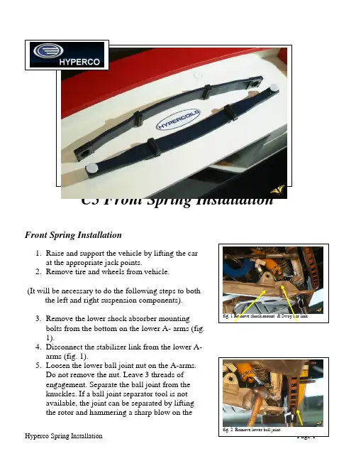
C5 Front Spring InstallationFront Spring Installation1.Raise and support the vehicle by lifting the carat the appropriate jack points.2.Remove tire and wheels from vehicle.(It will be necessary to do the following steps to boththe left and right suspension components).fig. 1 Remove shock mount & Sway bar link3.Remove the lower shock absorber mountingbolts from the bottom on the lower A- arms (fig.1).4.Disconnect the stabilizer link from the lower A-arms (fig. 1).5.Loosen the lower ball joint nut on the A-arms.Do not remove the nut. Leave 3 threads ofengagement. Separate the ball joint from theknuckles. If a ball joint separator tool is notavailable, the joint can be separated by liftingthe rotor and hammering a sharp blow on thefig. 2 Remove lower ball jointside of the knuckle right on the ball joint area(fig. 2).Front Spring Installation cont’6.Place a support under each A-arm one at a timeand remove the ball joint nut. Slowly lower theA-arm (fig. 1).7.Remove the spring retainer brackets (fig.3).8.Remove the original spring by moving itto one side, in order to clear the otherside lower A-arm.9.Clean any road dirt from the lower a-armsand cradle.You are now ready to install your new front spring. Apply a light amount of anti-seize on the thread and a small amount of grease on the bottom of the adjuster, aiding you later when your ride height and weights are adjusted. Install your new front spring adjusters into your Hyperco spring until they are seated.1.Install the new Hyperco spring into the cradlemount locations and lightly tighten the springretainer brackets (fig. 4). Care should be takento assure the spring is properly centered.Alternate the tightening of each retainer bracketa turn at a time to assure proper alignment. (fig.5).2.Place a support under both lower A-arms.Slowly raise the A-arms. Install and tighten the ball joint nut. (ball joint nuts torque 52 lb. Ft.)3.Connect the stabilizer link into the lower A-arms and tighten. (production stabilizer link nut53 lb. Ft.). If links are aftermarket follow theirtorque settings.fig. 4 Install spring into position fig. 3 Remove lower a-arm bolts4.Install and tighten the lower shock absorbermounting bolts into the bottom on the lower A-arms. (shock absorber lower mounting nuts 21lb. Ft.)5.Tighten the spring retaining bolts. (springretaining bolts 46 lb. Ft.)6.Install wheels and torque to properspecificationsRear Spring Installation1.Raise and support the vehicle.2.Remove tire and wheels from vehicle.3.Support the spring ends and remove the boltsand insulators retaining the spring to the lowercontrol arms (fig. 6).4.Remove the rear spring mounting brackets fromthe cross member.5.Remove the original spring.6.Clean any road dirt from the lower a-arms andcradle.You are now ready to install your new rear spring.1.Install your new Hyperco spring into the cradleand lightly tighten the retainer mountingbrackets.2.Support the left end of the spring and installbolt, insulators and nut. A light amount of anti-seize on the tread will aid latter when adjustingthe ride height.3.Support the right end of the spring and installbolt, insulators and nut. Again a light amount ofanti-seize on the tread will aid latter whenadjusting the ride height.4.Center spring and slowly tighten the springmounting bolts to the cradle (fig 7) (Springretaining bolts 46 lb. Ft.). fig. 6 Support & Remove spring bolts fig. 7 Center and tighten spring retainers5.Install wheels and torque to properspecificationsRide Height, Alignment and Corner WeightingVehicle can now be lowered from hoist to the ground. Anytime the vehicle is raised it must be moved (at least forward and reverse) to settle ride height. Set ride height to desired height prior to alignment or scaling. Front ride height can be raised or lowered by adjusting the front spring adjuster. Rear ride height can be raised or lowered by adjusting the rear spring brackets.Alignments will vary as to the type of driving you plan to do. Autocrossing or competition track driving will require a more aggressive alignment. Consider you vehicle usage before settling on your alignment.Scaling or corner weighting should be done after your ride heights and alignment has been set. Corner weighting is highly recommended for optimum performance. Weight cannot be moved from front to rear however it will shift on the diagonal (i.e. leftrear/right front to right rear/left front).。
复合材料圆柱螺旋弹簧的刚强度分析金达锋;熊志远;杨永宝【摘要】本文中对与中空圆截面簧丝轴线成±45°铺层的复合材料压缩圆柱螺旋弹簧进行刚强度分析.基于层合板理论,利用纤维复合材料平板的剪切模量及各向同性材料弹簧刚度公式,理论导出了该类复合材料弹簧的刚度表达式.同时,基于蔡-希尔强度公式和杆件扭转理论,分别求出弹簧的极限压缩载荷与最大压缩位移.计算结果与实验数据较为接近.本研究为该类复合材料弹簧的设计提供一定的理论参考.【期刊名称】《汽车工程》【年(卷),期】2013(035)008【总页数】5页(P755-758,722)【关键词】复合材料;圆柱螺旋弹簧;刚度;强度【作者】金达锋;熊志远;杨永宝【作者单位】清华大学汽车工程系,汽车安全与节能国家重点实验室,北京100084;清华大学汽车工程系,汽车安全与节能国家重点实验室,北京100084;清华大学汽车工程系,汽车安全与节能国家重点实验室,北京100084【正文语种】中文前言随着社会发展,能源消耗使人类生存环境日益恶化,其中交通领域中的能源消耗所占比例越来越大,排放的污染物和温室气体也在成倍增加,因此实施交通低碳化是必然趋势[1]。
对于汽车行业来说,新产品设计迫切要求在满足强度和安全性能的前提下,尽可能地降低汽车的整备质量,提高汽车的动力性,减少燃料消耗,降低排气污染,而采用轻质材料是实现汽车轻量化的主要措施之一。
碳纤维复合材料除了具有轻质、高强度、低缺口敏感性的特点之外,还具有耐酸碱、耐风化的性能,这些特性较好地迎合了新一代汽车零部件对材料性能的要求。
复合材料的车身、发动机和传动轴等在汽车工业中已有应用[2]。
同样,复合材料弹簧也具有普通金属弹簧所不具有的优势,国内外的科研人员已对其进行过一些早期的探索性研究。
目前,已在汽车工业中应用的复合材料弹簧大多为板弹簧[3-5]。
圆柱螺旋弹簧虽是应用最广的一类弹簧,但纤维复合材料圆柱螺旋弹簧尚处于研究的初期阶段,工程实际中应用极少。

纯电动轻卡轻量化浅析摘要:随着纯电动汽车产业的迅速发展及国家政策的支持,纯电动轻卡越来越多的走进了我们的生活。
纯电动轻卡常应用于载货运输,当其装载货物量较多时,会面临驱动力不足及续驶里程短等问题,而汽车轻量化是解决这一问题的有效途径。
本文基于纯电动轻卡整车结构,结合前沿科学技术,对车架、车身、驱动电机和动力电池的轻量化展开探究,提出了纯电动轻卡轻量化的相关途径,为纯电动轻卡的轻量化设计提供指导。
关键词:纯电动轻卡;轻量化;车架;车身;动力电池;1 引言随着双碳目标的推进,国家环保治理的日益严格,作为城市物流车主力的轻卡逐渐实现了由传统燃油车型向新能源车型的转变。
2021年新能源卡车销量共计47534辆,其中轻卡销售35395辆,占到市场份额的74.5%,其中纯电动卡车占到了新能源卡车销量的95%以上。
无论是福田、东风、江淮、江铃等传统卡车企业,还是吉利、比亚迪等新进的卡车企业,都推出了相应的纯电动轻卡车型,如吉利远程E200,江淮帅铃i5等多种纯电动车型颇受消费者的喜爱。
纯电动轻卡的安静、舒适及零排放等良好的特性已经得到了消费者的认可,不仅仅减轻了驾驶员的劳动强度,也为城市提供了一个清洁安静的环境,同时,伴随着电商、物流、社区团购的兴起,纯电动轻卡必将迎来新的发展。
虽然纯电动轻卡的保有量越来越多,但其续驶里程短、充电桩不足等问题仍困扰着消费者,由于目前国内汽车用动力电池技术还没有取得革命性的突破,因此纯电动轻卡的轻量化就成为提高汽车续驶里程,减少充电次数的重要途径。
2 纯电动轻卡结构纯电动轻卡是基于传统燃油轻卡的驾驶室和底盘进行油改电设计,其在结构上主要由驾驶室、车架、动力电池、驱动电机、底盘系统及货厢等组成。
纯电动轻卡的驾驶室依托传统燃油轻卡驾驶室,结合纯电动卡车的特点,主要对底板进行了优化设计,整体与传统燃油轻卡驾驶室基本相同。
纯电动轻卡的车架沿用了传统轻卡的车架,由纵梁和横梁铆接而成。
纯电动轻卡为增加市场竞争力,提高续驶里程,其动力电池重量往往超过了1000kg,对动力电池进行轻量化也是提高续驶里程的重要途径。
工 程 塑 料 应 用ENGINEERING PLASTICS APPLICATION第46卷,第7期2018年7月V ol.46,No.7Jul. 201874doi:10.3969/j.issn.1001-3539.2018.07.014主副式复合材料板弹簧结构设计及性能验证周洲,肖罗喜,程杨,李建林,刘波,王明星,周滨(株洲时代新材料科技股份有限公司,湖南株洲 412000)摘要:针对某型新能源车板弹簧轻量化需求,设计开发了主副式结构复合材料板弹簧,主簧为金属簧,副簧为复合材料簧,从而有效结合各材料特性。
通过有限元应力分析与试验测试,发现在各工况下复合材料副簧最大应力为–469.6 MPa ,安全系数为1.7。
采用该结构形式的复合材料板簧,总重为20.24 kg ,相比于原金属板簧减重50%以上。
最终成型的主副式板弹簧刚度达标,并通过24万次台架疲劳试验与6 000 km 装车综合路试,主副簧外观与刚度无明显变化,满足该车的使用寿命。
关键词:主副式;复合材料板弹簧;疲劳试验;刚度中图分类号:TQ320.63 文献标识码:A 文章编号:1001-3539(2018)07-0074-04Structure Design and Performance Verification of Main and Secondary Composite Leaf SpringZhou Zhou , Xiao Luoxi , Cheng Yang , Li Jianlin , Liu Bo , Wang Mingxing , Zhou Bin(Zhuzhou Times New Material Technology Co., Ltd., Zhuzhou 412000, China)Abstract :Aiming at a type of new energy vehicle leaf spring lightweight demand , main and secondary type composite leaf spring was designed and developed ,the main spring was made of metal ,the auxiliary spring was made of comoposite ,which effectively combined the characteristics of each material. Finite element stress analysis and the experiments showed that under all the conditions of leaf spring ,maximum stress was –469.6 MPa ,and the safety coef ficient was 1.7. The composite spring with this structure had a total weight of 20.24 kg ,which was more than 50% less than the original metal leaf spring. The rigidity of the main and secondary leaf spring is up to standard ,and through the 240 thousand stage fatigue test and the 6000 km loading road test ,the appearance and rigidity of the composite leaf springs are not changed ,which meets the service life of the vehicle.Keywords :main and secondary ;composite leaf spring ;fatigue test ;stiffness板弹簧是汽车悬架重要的组成部分,传统合金钢板弹簧占到汽车质量的5%~7%。
汽车复合材料板弹簧的有限元分析及性能测试汽车复合材料板弹簧是现代汽车悬挂系统中的一种新型材料弹簧,它由多层玻璃纤维增强环氧树脂层和铝合金层组成。
该材料弹簧具有体积小、重量轻、抗疲劳性能好、寿命长等优点,为汽车行业带来了重大突破。
本文将从有限元分析和性能测试两个方面对汽车复合材料板弹簧进行探讨。
一、有限元分析有限元分析是一种重要的工程计算方法,可以对汽车复合材料板弹簧的力学性能进行数值模拟,以预测材料弹性变形、疲劳寿命、最大承载能力等重要指标。
通过有限元分析模拟,可以更好地理解和优化汽车复合材料板弹簧的设计和制造。
在有限元分析过程中,需要首先建立汽车复合材料板弹簧的三维模型,并对其进行网格化处理。
接着需要根据弹簧的实际工作环境、外载荷和边界条件等因素,建立合适的力学模型。
然后利用有限元软件进行模拟计算,得到板弹簧的应力、应变、位移等物理量分布规律。
最后根据模拟结果进行分析和评估。
在具体的有限元分析中,需要考虑材料的弹性模量、泊松比、热膨胀系数等参数。
还需要考虑板弹簧的几何结构、截面形状、厚度和叠层方式等因素。
这些因素都会对板弹簧的强度、刚度和疲劳寿命等性能产生重要影响。
因此,有限元分析的结果可以为汽车复合材料板弹簧的设计和制造提供重要参考依据。
二、性能测试为了验证有限元分析的结果,需要进行汽车复合材料板弹簧的性能测试。
性能测试可以直接测量弹簧的实际物理量,如位移、应力、应变等,从而检验有限元分析的准确性和信度。
常见的汽车复合材料板弹簧性能测试方法包括三点弯曲试验、循环荷载试验、疲劳寿命试验等。
其中,三点弯曲试验是最基本的试验,可测量板弹簧的弹性模量、屈服强度、极限承载力等力学指标;循环荷载试验可以模拟板弹簧的实际工作环境,测量其疲劳寿命和断裂机理;疲劳寿命试验则可以评价板弹簧在长期疲劳作用下的耐久性和可靠性。
在性能测试中,需要特别注意汽车复合材料板弹簧的热膨胀系数对测试结果的影响。
因为板弹簧由不同的材料复合而成,各层材料的热膨胀系数不一致,容易引起板弹簧在变温作用下的应力和变形。

复合材料板簧在汽车上的应用作者:刘慧杨锁望王晓地范晓轩刘雷雷周震华来源:《新材料产业》2020年第04期节能减排给予汽车工业和研发人员持续的挑战,减轻汽车质量对汽车的发展具有重要的意义。
2012年国务院颁布的《节能与新能源汽车产业发展规划(2012-2020)》指出,到2020年,当年生产的乘用车平均燃料消耗量降至5.0L/100km。
减轻汽车自重,不仅可以降低对原材料的消耗,降低成本,还可以极大地节能减排,同时提高汽车的动力性能。
汽车的轻量化设计已成为当今汽车产业发展的重要研究方向。
现代汽车底盘弹簧的分类主要包括钢制螺旋弹簧和钢板弹簧。
家用汽车主要以螺旋弹簧为主,而卡车、厢式货车等重型汽车主要使用钢板弹簧。
近年来,由于复合材料技术的发展,玻纤增强型复合材料板簧发展成为应用在汽车悬架上的新型轻量化解决方案,其在汽车上的应用主要分纵置和横置2种结构形式。
纵置板簧多用于货车上,结构与传统钢板弹簧相似;横置板簧多用于汽车,对悬架布置影响较大;材料上,由于玻纤增强型板簧材料的各向异性特点,对设计校核也提出了新的挑战。
本文简述了复合材料板簧的应用现状和工艺过程,并以玻纤增强型复合材料板簧为例研究其在汽车上的应用方法和原理,为该技术的研究和应用提供参考。
1复合材料板簧的应用发展、材料和工艺1.1复合材料板簧的发展历程意识到复合材料板簧所能带来的优异性能,越来越多的厂商竞相研制并取得了一定的成果。
目前,传统的钢制板簧正逐渐被复合材料板簧取代。
这一发展大体经历了3个阶段。
第1阶段是1970年以前,为原理性实验探索阶段。
这期间,有大量的应用理论分析文章和阶段性研制报告被发表。
第2阶段是1980年以前,为实用化研制阶段。
伴随塑料工业的发展,这期间纤维增强塑料(Fibergla ss Reinfo rcedPlastics,FRP)研制成功,这种材料不仅耐温、耐磨,而且价格合适。
同时,汽车市场正向小型化和轻型化方向发展,特别是第2次石油危机以后,为了减轻汽车自重、降降油耗,汽车厂商积极投入复合材料板簧的研制,促进了复合材料板簧从理论向实际应用的发展,并成功美国实现FRP板簧在投入应用。
2021年(第43卷)第6期汽车工程Automotive Engineering2021(Vol.43)No.6复合材料板簧的迟滞特性建模与试验研究*刘鹤龙1,史文库1,高蕊2,陈志勇1,陈晃2,孙云龙3(1.吉林大学,汽车仿真与控制国家重点实验室,长春130022;2.中国重汽集团汽车研究总院,济南250100;3.哈尔滨玻璃钢研究院有限公司,哈尔滨150036)[摘要]运用Bouc⁃Wen摩擦学理论建立了复合材料板簧的迟滞特性模型,根据台架试验测得的动态力-位移曲线,利用改进的乌鸦搜索算法(MCSA)进行了模型的参数辨识。
仿真结果与试验结果吻合较好,表明该模型能准确预测复合材料板簧的迟滞特性。
建立考虑复合材料板簧迟滞特性的整车7自由度动力学模型,分析了在随机路面激励下,复合材料板簧迟滞特性对整车动态响应的影响。
结果表明,复合材料板簧的迟滞特性使簧载质量的质心加速度增加,板簧的回复力增大,而悬架的动挠度减小。
该研究为复合材料板簧的整车匹配和精细化动力学建模提供参考。
关键词:复合材料板簧;迟滞特性;平顺性;Bouc⁃Wen模型;乌鸦搜索算法Modeling and Experimental Study on Hysteresis Characteristic ofComposite Leaf SpringsLiu Helong1,Shi Wenku1,Gao Rui2,Chen Zhiyong1,Chen Huang2&Sun Yunlong31.Jilin University,State Key Laboratory of Automotive Simulation and Control,Changchun130022;2.Automotive Research Institute of China National Heavy Duty Truck Group Co.,Ltd.,Jinan250100;3.Harbin FRP Institute Co.,Ltd.,Harbin150036[Abstract]Bouc⁃Wen tribology theory is applied to the setting up of the hysteresis characteristic model of composite leaf springs,and according to the dynamic force⁃displacement curves obtained by bench test,the model parameters are identified by using the modified crow search algorithm(MCSA).The simulation results well agree with the test ones,showing that the model can accurately predict the hysteresis characteristic of composite leaf spring.A seven DOF vehicle dynamic model is established with consideration of the hysteresis characteristic of com⁃posite leaf spring,and the influence of the hysteresis characteristic of composite leaf springs on the dynamic re⁃sponse of vehicle under random road excitation is analyzed.The results indicate that the hysteresis characteristic of composite leaf spring increases the mass⁃center acceleration of sprung mass and the restoring force of leaf spring,and reduces the dynamic deflection of suspension.This study provides a reference for the vehicle matching and the refined dynamic modeling of composite leaf springs.Keywords:composite leaf spring;hysteresis characteristic;ride comfort;Bouc⁃Wen model;crow search algorithm前言随着能源短缺的问题日益凸显和新能源汽车对续航里程的要求逐渐提高,汽车轻量化技术的发展得到了广泛的关注。

精心整理汽车钢板弹簧设计1、 结构优缺点分析,决定设计的结构方案。
2、 确定钢板弹簧材料许应力,根据静挠度f c 用《材料力学》简支梁挠度公式,初步确定钢板截面尺寸、、形状、惯性矩、片数。
3、 根据已知的板簧支点距离,U 型螺栓距离、片数,用作图法求得各片钢板弦长,4、 5、 6、7、 态下弧高计算。
8、 计算钢板弹簧总成在自由状态下的曲率半径R 0.9、 计算各片钢板在自由状态下的曲率半径R i ,直至接近为止。
10、 计算各片钢板弧长(各片钢板在支承点之间的实际长度)。
11、 绘图:在各片钢板处于伸直状态下绘制总成图。
制图符合常规要求外,图上还需要列表注明各片钢板实际长度、曲率半径、总成检验弧高。
12、钢板弹簧总成在极限工况下的长度验算。
13、钢板弹簧卷耳和销轴的验算。
14、卷耳衬套的设计和验算。
I0:根部惯性矩I0=W0:根部断面系数W0=C=*汽车多片钢板弹簧主要设计算计式与参数表对称钢板弹簧不对称钢板弹簧参数许用值刚度C j=48EI0/[(L-S/2)3δ]S:平直段长度C j=3EL2I0[L12(L2-S/4)2+L22(L1-S/4)2]δ弹性模量E=2.058*105N/mm2弹性极限σe=90kg/mm2=882N/mm2屈服极限σs=120-125kg/mm2静挠度F j=p m(L-S/2)3δ/(48EI0)F j=【L12(L2-s/4)2+L22(L1-S/4)2】δp m/(3EL2I0)静应力σ=形状系数δ=【-2η+η2(-lnη)】各片厚度相同时δ=1.5/1.04【1+1/(2η)】静应力:前簧σ=343-441N/mm2后簧σ=441-539N/mm2副簧σ=196-245N/mm2平衡簧σ=343-441N/mm2满载负荷Pm=Cjσm/δ验证负荷Pe=Cjσe/δ预压负荷Ps=Cjσs/δ各片长度L i=(L z/2-L d/2)h3/等厚度时L I=(L z/2-L d/2)/nL z/Ld…作用长/短片长n…小于L z的片数:满载自振频率:N m=300/Fj1/2(次/分,Fj-cm前簧N m=100-110(次/分)(F J=74.5-90mm)后簧N mm=110-125mm(F j=57.5-74.5mm)根部极限应力:σmax=δ(F j+F d)曲率半径弧长计算:1、根据H/L查表..Q值—R=L/Q2、R=L2/(8H)(近似计算)弦长计算:R=[H2+(L/2)2]/(2H)H=R-(R2-L2/4)1/2知各弧高求总等截面板簧的设计要点与思路一、钢板弹簧设计的已知条件1、总成类型:a前簧、后簧、副簧或平衡簧;b等截面簧、变截面簧或复合簧。
(19)中华人民共和国国家知识产权局(12)发明专利申请(10)申请公布号 (43)申请公布日 (21)申请号 201711352759.6(22)申请日 2017.12.15(71)申请人 武汉理工大学地址 430070 湖北省武汉市洪山区珞狮路122号(72)发明人 王钧 代巍 杨小利 张斌 苏晓岗 (74)专利代理机构 湖北武汉永嘉专利代理有限公司 42102代理人 邬丽明(51)Int.Cl.B32B 27/02(2006.01)B32B 17/12(2006.01)B32B 27/12(2006.01)B32B 9/04(2006.01)B32B 9/00(2006.01)B32B 17/02(2006.01)B32B 27/32(2006.01)B32B 27/34(2006.01)B32B 27/36(2006.01)B32B 27/30(2006.01)B32B 37/00(2006.01)(54)发明名称一种高耐疲劳复合材料汽车板簧及其制作方法(57)摘要本发明公开了一种高耐疲劳复合材料汽车板簧及其制作方法。
该高耐疲劳复合材料汽车板簧包括叠层铺放的至少一层单向纤维层以及套设于单向纤维层外表面的至少一层二维编织套管。
制作方法为:叠层铺放至少一层单向纤维层;将所述至少一层单向纤维层外套所述至少一层二维编织套管,制备成纤维预成型体;将纤维预成型体放入成型模具中,采用成型工艺浸渍、固化、脱模、修剪,即得到所述复合材料汽车板簧。
本发明利用了二维编织套管中纤维连续、角度可控、附型性好的特性,制备了具有高耐疲劳和抗层间剪切优异的汽车板簧,该制备工艺简单,有效避免了传统纯单向铺放纤维板簧环向没有纤维约束、耐疲劳性差、三维编织预成型体工艺复杂的问题。
权利要求书1页 说明书3页 附图2页CN 108099317 A 2018.06.01C N 108099317A1.一种高耐疲劳复合材料汽车板簧,其特征在于,所述高耐疲劳复合材料汽车板簧包括叠层铺放的至少一层单向纤维层以及套设于所述单向纤维层外表面的至少一层二维编织套管。