Module 1 Version 2 介绍-updated
- 格式:ppt
- 大小:7.71 MB
- 文档页数:42

Honeywell WEBs-N4 Installation GuideVersion 4.9.0.198September 2020Table of ContentsA BOUT THIS G UIDE (3)D OCUMENTATION (3)S YSTEM R EQUIREMENT FOR WEB STATION-N4 (3)Operating System & Software Dependencies (4)Using Web Launcher with Niagara 4.9 (5)WEB STATION-N4I NSTALLATION P ROCEDURE (6)About this GuideThis document is part of the WEBStation-N4 documentation library. WEBStation-N4 software is distributed via the Honeywell Buildings Forum. The platform requirements needed are mentioned in WEBs N4.9.0.198 Software Release Bulletin.For the latest product data, visit or Honeywell Building Controls.NOTE: This version of Honeywell WEBs-N4.9.0.198 is compatible with Spyder Model 5, CIPer Model 10, and WEB-8000 controllers. CIPer Model 30 and CIPer Model 50 controllers are not compatible with this release. DocumentationEach view/dialog is provided with a Help button. Click the Help button to open a help window, that explains the functionality of the displayed view. Alternatively, each view has a help page which can be opened by pressing the F1 key on the keyboard or navigate to Help tab in menu items and click Help On View.Refer the Honeywell Buildings Forum Documents for all latest WEBs-N4 product related documentation. System Requirement for WEBstation-N4IMPORTANT NOTEN4.9 supports only 64-bit installations. So, installing N4.9 will generate a new host ID, if you made a 32-bit in-stallation in the previous N4.X versions. Be sure to transfer your Niagara Workbench license from your previous32-bit host ID to your new 64-bit host ID.To use Lon devices with station running in Windows, use LON tunneling with JACE or use LON/IP.Operating System & Software DependenciesWEBs-N4 is supported on the following listed Microsoft Windows operating systems. The application installation in-cludes Oracle’s Java Runtime Environ ment (JRE) and does not depend on any other software to run.Using Web Launcher with Niagara 4.9Web Launcher 20.1.3 was recently revamped for N4.9 to include essential software dependencies updates along with critical defect fixes. This version of Web Launcher has Java version 8 update 252 and certificate management has been updated to work with N4.9 along with any legacy or prospective release. Prior to using Web Launcher with N4.9, customer should update Web Launcher accordingly (see steps below).How to update Web Launcher?Web Launcher has a feature to check for updates over the internet and prompts the user when a new version is avail-able in the cloud. However, existing version of Web Launcher has a bug that prevents a smooth update. Users will be required to perform a fresh install by downloading the latest version from the cloud via the station web Login page. Click on the Niagara Web Launcher Installer link on the station's Web Launcher Web Page, which can be reached via the link on the Login page itself. Once the download is successful, click on the msi file and follow the installation wiz-ard. You do not have to uninstall the older version. The new installation will automatically update to the latest version.WEBstation-N4 Installation Procedure1.Double click the executable file (Installer_x64.exe)The WEBStation-N4 Installation Program window opens, showing information such as build version, date etc.Click Next to proceed the installation.2.Click Yes to agree with the End User License Agreement [EULA] and Next to continue the installation.Or Click No to cancel the installation.3.The installer loads C:\Honeywell\WEBStation-N4-4.9.0.198 path by default. If this path does not exist,the installer displays warning message, Click Yes to create the folder. Click Next to continue installation.4.If you do not wish to install the WEBStation-N4 in the default directory, click Browse to change the path,and click Next to continue.NOTE: If you are performing a new installation, the installer prompts you to set a system passphrase for en-cryption purposes, as shown in the following image.The system passphrase is used to protect sensitive information stored on all WEBs systems, and on the SD card in WEB-8000 controllers. The system passphrase i s assigned as the file passphrase for “portable files, such as backups and station copies, and is used to encrypt those files. During operations in which you transfer encrypted files to a system (restoring backups, transferring a station, etc.) you are prompted to sup-ply the file passphrase, if it doesn’t match the system passphrase. The system passphrase defaults to the factory default platform password.During commissioning, you will be prompted to change the default system passphrase.NOTE: It is important to remember the system passphrase and keep it safe. If you lose the system pass-phrase, you will lose access to encrypted data. To change the system passphrase, use the Platform Admin-istration tool.5.Niagara Deamon User Home directory is used to store Niagara Deamon user’s data and to run Niagarastations. By default, the directory is created under C:\ProgramData\Niagara4.9\Webs as shown below.If this path does not exist, the installer displays warning message, requesting to create the folder. Click Yes to continuee the Browse option to change default folder location, if desired.Or Click Next to continue.7.Check the options to install Desktop Shortcuts, if needed. Click Next to run the installation.8.After completing of the installation, the installer displays message “WEBStation-N4 installation iscomplete".9.Check the required options and click Finish to complete the installation process.10.Once the installation is finished, license get installed automatically. Click Continue to run WEBstation-N4.WEBs-N4 Workbench opens as shown below.。
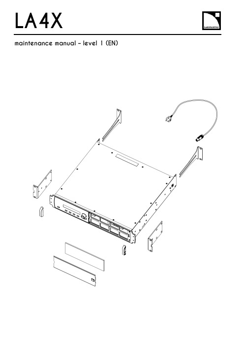
LA4X Arraymaintenance manual – level 1 (EN)ContentsDocument reference: LA4X maintenance manual - level 1 (EN) version 2.0Distribution date: March 20, 2017© L-Acoustics. All rights reserved.No part of this publication may be reproduced or transmitted in any form or by any means without the express written consent of the publisher.ContentsContentsSafety instructions 4 Symbols 4 Revision history 5 Introduction 6 1Equipment and tools 7 2Quality Control 8 3Troubleshooting and diagnosis 10 Diagnosis table (10)Exploded view (16)Working time (16)4Disassembly and Reassembly procedures 17 D/R 001 – REAR BRACKETS (17)D/R 002 – SIDE BRACKETS (18)D/R 003 – GRILL and FOAM FILTER (19)D/R 004 – Power plug (20)D/R 004 bis – FRONT HANDLE (21)Glossary 22 Appendix: KR list 23Safety instructionsSafety instructions1.Strictly follow the sequence of successive steps in all procedures.2.This manual contains the maintenance operations authorized for the end users.Performing another operation exposes to hazardous situations.3.Never incorporate equipment or accessories not approved by L-Acoustics®.4.Do not expose the apparatus to extreme conditions.Do not expose the apparatus to dusty environments, moisture or excessive heat when storing orperforming maintenance procedures.5.Do not store the product on an unstable cart, stand, tripod, bracket, or table.6.Never use a faulty apparatus.An apparatus showing any sign of issue must immediately be put aside and withdrawn from use.7.Contact L-Acoustics for advanced maintenance.Any unauthorized maintenance operation will void the warranty.Before sending a product to L-Acoustics for maintenance, save all user presets to files usingLA Network Manager.SymbolsThe following symbols are used in this document:This symbol indicates a potential risk of harm to an individual or damage to the product.It can also notify the user about instructions that must be strictly followed to ensure safe installation or operation of the product.This symbol indicates a potential risk of electrical injury.It can also notify the user about instructions that must be strictly followed to ensure safe installation or operation of the product.This symbol notifies the user about instructions that must be strictly followed to ensure proper installation or operation of the product.This symbol indicates the equipment, tools, and spare parts required to perform a procedure.This symbol notifies the user about complementary information or optional instructions.Revision historyRevision historyDocument identification Distribution date ModificationsLA4X_MM1_EN_1.0 June 10, 2014 Initial versionLA4X MM1 EN version 2.0 March 20, 2017 - Added D/R 004 bis – FRONT HANDLE- Updated Exploded view- Updated Appendix: KR listIntroductionIntroductionThis manual is intended for end users and gathers the level 1 procedures.This manual contains the maintenance operations authorized for the end users.Performing another operation exposes to hazardous situations.Diagnosis tableThis section contains the diagnosis tables and procedures to identify the issues and how to address them.Exploded viewThis illustration gives an overview of the order in which the elements must be disassembled and reassembled. Each assembly refers to the corresponding module, D/R procedure and inspection procedure (if any).Disassembly and Reassembly proceduresThis section contains the maintenance procedures for each assembly identified in the exploded view.Quality ControlThese checks allow to detect an issue. The quality control must be performed regularly.It is mandatory to perform preventive maintenance actions on a regular basis.Insufficient upkeep of the product can void the warranty.Equipment and tools1Equipment and toolsThe following table is the complete list of equipment and tools required to perform all level 1 maintenance procedures on the LA4X amplified controller.* Refer to the documentation of the electric screwdriver manufacturer to obtain the setting corresponding to a given torque value. This setting can vary depending on the age of the tool. Verify it on a regular basis.Quality Control2Quality ControlThis procedure must be performed for periodic maintenance and to detect possible issues on a controller. ToolsNameaudio source with a known musical programLA NWMCAT5e U/FTP cablefull range loudspeakersubwooferear protectionsProcedureInspect the external structure of the controller for any lost or damaged part.To verify if the controller is clean, follow these steps:a.Disassemble the GRILL and the FOAM FILTER, see procedure D/R 003.b.Verify if the FOAM FILTER is clean.c.Look inside the controller through the front grill (do not touch any part) and verify if the inside is clean.d.Reassemble the GRILL and the FOAM FILTER, see procedure D/R 003.Plug the controller to mains and power it on.Verify if the LCD screen and all LED lit during the start-up sequence.To verify if the network functionalities of the controller work, follow these steps:a.Connect the controller to an Ethernet port of the computer hosting LA NWM.Use the CAT5e U/FTP cable.unch LA NWM.c.Verify if the controller can be put in online mode (refer to the LA NWM video tutorial).Verify if the latest version of firmware is installed (see the LA4X user manual or the LA NWM videotutorial).If not, update firmware from LA NWM.Select a known preset and verify if the indications displayed on screen are in accordance with it.To verify sound presence and quality on each output channel follow these steps:a.Plug the audio source to an input connector of the controller (IN A, IN B, IN C or IN D).b.Plug the full range loudspeaker to output connector OUT1.c.Select a corresponding preset.d.Select the routing from the audio source to OUT1.e.Play the musical program.f.Set the OUT1 gain to -40 dB.g.Unmute OUT1.h.Set the OUT1 gain to obtain a medium sound level.i.Verify if the sound is clear and undistorted.j.Mute OUT1.k.Repeat these steps for OUT2, OUT3 and OUT4.Quality Control There is a risk of ear damage due to high sound level.Use ear protections.To verify the power capability of each output channel follow these steps:a.Plug the audio source to an input connector of the controller (IN A, IN B, IN C or IN D).b.Plug the subwoofer to output connector OUT1.c.Select a corresponding preset.d.Select the routing from the audio source to OUT1.e.Play the musical program.f.Set the OUT1 gain to -40 dB.g.Unmute OUT1.h.Set the OUT1 gain to obtain a high sound level.i.Verify if the sound remains clear and undistorted up to the limit level.j.Mute OUT1.k.Repeat these steps for OUT2, OUT3 and OUT4.Troubleshooting and diagnosis3Troubleshooting and diagnosisDiagnosis tableFor any issue, follow the check sequence in the possible causes column.At each step, apply the inspection procedure (if exists) and consider the resulting diagnosis.Before applying a procedure, consider the EXPLODED VIEW to get acquainted with the disassembly/reassembly procedures to perform before and after.Troubleshooting and diagnosisPOWER CORD notconnected to mainsmains failure or wrongvoltagePOWER CORDdamagedother causecontroller connected to anon-compatible networkcondensing humidity intothe LCD screenother causeTroubleshooting and diagnosisTroubleshooting and diagnosisroom temperature too highFOAM FILTER cloggedcontroller not gettingenough cool airchannel x resourcessolicited to their limitsloudspeaker impedance toolowother causesporadic errorother causesfirmware update failureother causeTroubleshooting and diagnosisFAN blades blockedanythe mains failureoutputs mutedwrong input modewrong preset selectiongain value too low on the controlleraudio source not plugged or plugged into the wrong input connectoraudio source cable incorrectly plugged audio source cable damagedwrong settings on the audio sourcenon-audio bit stream audio source failureloudspeaker not plugged or plugged into the wrong output connector loudspeaker cable incorrectly plugged loudspeaker cable damagedloudspeaker damaged other causesTroubleshooting and diagnosisAES/EBU audio sourceconnected to anANALOG inputgain value too high onthe controlleroutput gain value toohigh on the audio sourceswitch to the analogfallback mode withwrong AES/EBU inputgain valuewrong preset selectionaudio source cableincorrectly pluggedaudio source cabledamagedwrong settings on theaudio sourceaudio source failureloudspeaker pluggedinto the wrong outputconnectorloudspeaker cableincorrectly pluggedloudspeaker cabledamagedloudspeaker damagedother causesTroubleshooting and diagnosisExploded viewThe following exploded view represents the external MODULES of the LA4X. Each MODULE is indicated by a circled number. The orange lines represent the disassembly/reassembly (D/R) order. Refer to the table below for more information.Working timeDisassembly and Reassembly procedures4 Disassembly and Reassembly proceduresD/R 001 – REAR BRACKETS Spare parts KR LABRACKETDisassembly procedureThis procedure describes how to replace the REAR BRACKETS of an LA4X amplified controller. Remove the two REAR BRACKETS pulling on them, see Figure 1.Figure 1: Removing the REAR BRACKETSReassembly procedureThis procedure describes how to mount the REAR BRACKETS kit to an LA4X amplified controller. Insert the two REAR BRACKETS pushing on them until they are locked, see Figure 2.Figure 2: Mounting the REAR BRACKETSDisassembly and Reassembly proceduresD/R 002 – SIDE BRACKETSToolsNameelectric screwdriverTorxSpare partsKR LA4XEQAVDisassembly procedureThis procedure describes how to remove the SIDE BRACKETS from an LA4X amplified controller.Undo the four Torx® screws from the locations indicated in Figure 3.Use the electric screwdriver with the Torx® T10 bit.Figure 3: Removing a SIDE BRACKET Remove the SIDE BRACKET from the controller.Repeat these steps for the other SIDE BRACKET.Reassembly procedureThis procedure describes how to mount a SIDE BRACKETS kit to an LA4X amplified controller.Position a SIDE BRACKET on the controller.Drive four Torx® screws to the locations indicated in Figure 4.Use the electric screwdriver with the Torx® T10 bit. Torque to 1 N.m.Figure 4: Mounting a SIDE BRACKET Repeat these steps with a second SIDE BRACKET on the other side of the controller.Disassembly and Reassembly proceduresD/R 003 – GRILL and FOAM FILTER ToolsName3.5 mm flat screwdriverSpare parts KR LA4XGRI KR LA4XMOU Disassembly procedureThere is a risk of electrical injury and a risk of trapping finger/handBefore any maintenance operation, disconnect the controller from mains and wait for 1 minute so the capacitors discharge completely.This procedure describes how to remove the GRILL and FOAM FILTER from an LA4X amplified controller. Insert the head of the screwdriver in the hole indicated in Figure 5.Figure 5: Removing the GRILLPush the internal latch with the screwdriver and pull out the right side of the GRILL. Push the internal latch with the screwdriver again until the latch comes out of the hole. Remove the GRILL and the FOAM FILTER from the controller.If the FOAM FILTER is intended to be cleaned, use mild dishwashing detergent or soap and then dry it.Reassembly procedureThis procedure describes how to mount a GRILL kit and a FOAM FILTER kit to an LA4X amplified controller. Place a FOAM FILTER into the GRILL.Insert the left side of the GRILL into the controller. Insert the internal latch into the controller. Use the screwdriver.Push on the right side of the GRILL until hearing a click sound.Disassembly and Reassembly proceduresD/R 004 – Power plugToolsNamewire stripping pliersStanley knifescrewdriver adapted to the new powerplugSpare partsSafetyThere is a risk of electrical injury when the high-voltage capacitors are charged.Before the maintenance operation, disconnect the POWER CORD from the mains and from the controller.Replacement procedureThis procedure describes how to replace the power plug on a POWER CORD.Unplug the POWER CORD from the mains.Unplug the POWER CORD from the controller.Cut the POWER CORD near the power plug.Use the Stanley knife.Strip the three wires of the POWER CORD on a length compatible with the new plug.Use the Stanley knife and the wire stripping pliers.Fix the three wires on the new plug according to the color code of Table 1.Use the screwdriver.Table 1: Wire color codeDisassembly and Reassembly proceduresD/R 004 bis – FRONT HANDLEToolsNameelectric screwdriverTorxSpare partsG03255Disassembly procedureThis procedure describes how to remove the FRONT HANDLE from an LA4X amplified controller.1.Undo the two Torx® screws from the locations indicated in Figure 6.Use the electric screwdriver with the Torx® T15 bit.2.Remove the FRONT HANDLE from the controller.3.Repeat these steps for the other FRONT HANDLE.Reassembly procedureThis procedure describes how to mount a FRONT HANDLE to an LA4X amplified controller.FRONT HANDLES can only be mounted on compatible FRONT STRUCTURE.To upgrade a controller with a non-compatible FRONT STRUCTURE, contact your L-Acoustics representative.Self-drilling screwsFor safety reasons, always reassemble new FRONT HANDLES.1.Position a FRONT HANDLE on the controller.2.Drive two Torx® screws to the locations indicated in Figure 6.Use the electric screwdriver with the Torx® T15 bit. Torque to 1 N.m3.Repeat these steps for the other FRONT HANDLE.Figure 6: Mounting a FRONT HANDLEGlossaryGlossaryCE EuropeCN ChinaD/R disassembly/reassemblyKR Replacement KitLA NWM La Network Manager remote control softwareMODULE part of an amplified controller, written in uppercase characters N.m newton meter, international torque unit, 1 N.m = 9 in.lb fUS United StatesAppendix: KR list Appendix: KR listL-Acoustics, an L-Group Company13 rue Levacher Cintrat – 91460 Marcoussis – France+33 1 69 63 69 63 –********************L-Acoustics GmbH Steiermärker Str. 3-5 70469 StuttgartGermany+49 7 11 89660 323L-Acoustics Ltd.PO. Box Adler Shine - Aston HouseCornwall Avenue - London N3 1LFUnited Kingdom+44 7224 11 234L-Acoustics Inc.2645 Townsgate Road, Suite 600Westlake Village, CA 91361USA+1 805 604 0577。

July 16, 2014 MPLAB Code Configurator Version 2.0.1 Release Notes for MPLAB® Code Configurator v2.0.1 1 What is MPLAB Code Configurator (MCC)The MPLAB®Code Configurator generates seamless, easy to understand C code that is inserted into your project. It enables, configures and utilizes a rich set of peripherals across select list of devices. It is integrated into MPLAB®X IDE to provide a very powerful and extremely easy to use developmentplatform.2 System Requirements•MPLAB® X IDE v2.10 or later•XC8 compiler v 1.31 or later•XC16 compiler v 1.21 or later3 Documentation SupportThe MPLAB® Code Configurator User’s Guide (DS40001725) may be found on the MPLAB® CodeConfigurator page on the Microchip web site. /mcc4 Installing MPLAB® Code ConfiguratorBasic steps for installing MPLAB® Code Configurator are given here.To install the MPLAB® Code Configurator Plugin:•In the MPLAB® X IDE, select Plugins from the Tools menu•Select the Available Plugins tab•Check the box for the MPLAB® Code Configurator, and click on Install5 What’s New•This is the dot release to fix the issues identified in the Repairs and Enhancement section.July 16, 2014 MPLAB Code Configurator Version 2.0.15.1 Supported Devices5.1.1 8 bit Devices•PIC12(L)F1501 •PIC16(L)F1783 •PIC16(L)F1946•PIC12(L)F1822 •PIC16(L)F1784 •PIC16(L)F1947•PIC12(L)F1840 •PIC16(L)F1786 •PIC18(L)F23K20•PIC16(L)F1503 •PIC16(L)F1787 •PIC18(L)F24K20•PIC16(L)F1507 •PIC16(L)F1788 •PIC18(L)F25K20•PIC16(L)F1508 •PIC16(L)F1789 •PIC18(L)F26K20•PIC16(L)F1509 •PIC16(L)F1823 •PIC18(L)F43K20•PIC16(L)F1512 •PIC16(L)F1824 •PIC18(L)F44K20•PIC16(L)F1513 •PIC16(L)F1825 •PIC18(L)F45K20•PIC16(L)F1516 •PIC16(L)F1826 •PIC18(L)F46K20•PIC16(L)F1517 •PIC16(L)F1827 •PIC18(L)F23K22•PIC16(L)F1518 •PIC16(L)F1828 •PIC18(L)F24K22•PIC16(L)F1519 •PIC16(L)F1829 •PIC18(L)F25K22•PIC16(L)F1526 •PIC16(L)F1847 •PIC18(L)F26K22•PIC16(L)F1527 •PIC16(L)F1933 •PIC18(L)F43K22•PIC16(L)F1704 •PIC16(L)F1934 •PIC18(L)F44K22•PIC16(L)F1708 •PIC16(L)F1936 •PIC18(L)F45K22•PIC16(L)F1713 •PIC16(L)F1937 •PIC18(L)F46K22•PIC16(L)F1716 •PIC16(L)F1938•PIC16(L)F1782 •PIC16(L)F19395.1.2 16 bit Devices•PIC24F(V)08KM101•PIC24F(V)08KM102•PIC24F(V)08KM202•PIC24F(V)08KM204•PIC24F(V)16KM102•PIC24F(V)16KM104•PIC24F(V)16KM202•PIC24F(V)16KM204•PIC24FJ128GA306•PIC24FJ128GA308•PIC24FJ128GA310•PIC24FJ64GA306•PIC24FJ64GA308•PIC24FJ64GA3106 Repairs and Enhancements# ID Description Device(s)PIC24 devices1. MCC-1147 The system module wasn’t reloading the correct settingswhen the clock source was FRCPIC24 devices2. MCC-1163 Multiple Initializers of the Timer module weren’t showing thetimer limits correctlyThe following are enumerated issues for the MPLAB® Code Configurator.# ID Description Device(s)1. MCC-1094 The I2C Slave driver fails to acknowledge the first data bytesent by the Master after the Slave address is decoded PIC18F46K20,PIC16F1938, PIC16F19372. MCC-1084 I2C drivers do not support Polling mode All3. MCC-1083 RETCGF is missing description PIC24F GA310 family4. MCC-1082 CLC input pins(CLCIN0 & CLCIN1) are mentioned in asingle row as CLCINxPIC16F5. MCC-1069 MCCP Compare: Multiple Initializers don't set OCxEN bits PIC24F KM family6. MCC-1063 IC : When the TMR3 or TMR5 are not available raise analert if they are selectedPIC24F GA310 family7. MCC-1049 FVR module does not have the option of producing 4.096V PIC12LF18408. MCC-1048 APFCON value is not updated when a module is deleted PIC12F15019. MCC-1043 DAC: Register name DACCON1 doesn't match with theregister name in datasheet.PIC18F46k2210. MCC-1039 CVREF pin when accessed by CMP should throw alertwhen released in CVRPIC24 devices11. MCC-1004 Create main.c question appears even when main.c exists All12. MCC-997 PLL input values need to be limited PIC18FxxK2213. MCC-869 PIC12F1822 DAC VREF+ Missing in Pin Manager window,since VREF+ pin ia part of ADC.PIC12F18228.1 The Microchip Web SiteMicrochip provides online support via our web site at . This web site is used as a means to make files and information easily available to customers. Accessible by using your favorite Internet browser, the web site contains the following information:•Product Support – Data sheets and errata, application notes and sample programs, design resources, user’s guides and hardware support documents, latest software releases and archived software• General Technical Support – Frequently Asked Questions (FAQs), technical support requests, online discussion groups/forums (), Microchip consultant program member listing• Business of Microchip – Product selector and ordering guides, latest Microchip press releases, listing of seminars and events, listings of Microchip sales offices, distributors and factoryrepresentatives8.2 Additional SupportUsers of Microchip products can receive assistance through several channels:•Distributor or Representative•Local Sales Office•Field Application Engineering (FAE)•Technical SupportCustomers should contact their distributor, representative or field application engineer (FAE) for support. Local sales offices are also available to help customers. A listing of sales offices and locations is available on our web site.Technical support is available through the web site at: 。

update的用法及短语一、介绍在现代英语中,update 是一个非常常用的动词和短语。
它可以用于多种场景,并且被广泛应用于各个领域中。
本文将详细介绍 update 的使用方法以及相关的常用短语。
二、基本含义及用法update 的基本含义是“更新”或“升级”。
它可以用作及物动词,也可以用作名词和形容词。
“更新”的意思是使某物成为最新版本或状态,而“升级”则表示对某物进行改进或提高。
1. 及物动词:a) update something:指对某事物进行更新。
- You need to update your software regularly to ensure security.(你需要定期更新软件以保证安全性。
)- The professor updated his lecture notes before the start of the new semester.(教授在新学期开始前更新了讲义。
)b) update somebody on something:向某人通报最新情况。
- I will update you on the progress of our project tomorrow.(明天我会告知你我们项目的进展情况。
)- Please keep us updated on any changes in your contact information.(请随时告知我们您联系方式的任何变化。
)2. 名词:a) an update:表示一份最新消息或资讯。
- Have you heard the latest updates about the upcoming elections?(你有关注关于即将到来的选举的最新消息吗?)- I'll give you an update on the situation as soon as I have more information.(一旦我获得更多信息,我会告诉你有关情况的最新情报。

Exos®AP-BV-1Release NotesPart Number204208200-00,A•November2022DescriptionThis package delivers firmware for Exos®AP-BV-1storage enclosure.Update recommendationThis is a recommended firmware update.Installation instructionsThis is a recommended firmware update.To install this firmware,see the Exos AP2U12-B,2U24-B,5U84-B System Integration Handbook.Issues fixed in CLPD firmwareV3.08l Added support for the BMC reset expander by register(0xCA,bit1).l Added support for masking the function of CPU FSR by register(0xCA,bit2)when Midplane CPLD updates. Issues fixed in BIOS firmwareV1.03l Changed setup option Advance>CSM>Option ROM execution>Storage default to Do not launch.V1.02l Fixed7292P CPU speed not running at2.0GHz.(Pstate0is not set correctly).V1.01l Upgraded AMD AGESA code to Embedded Rome PI1.0.0.7.V1.00l Added PSU Version/DSP Version/CRC to SMBIOS Type39RevisionLevel field.l Fixed Redfish conformance test failure.V0.08l Fixed the issue where the virtual CD-ROM couldn’t be used in legacy mode.l Fixed the issue where BIOS v0.07couldn’t detect TPM.l Deleted the Redfish mapping ID IPMI800-IPMI812.V0.07l Fixed a hot swap issue where sometimes the IOM1has PCI PERR in sel log and PCI-e error in dmesg after IOM0hot removal followed by IOM0hot insertion.l Fixed an issue where,after successfully upgrading BIOS firmware,the system automatically rebooted with default boot priority but then hung at task Downloading NBP file.l Changed the NTB port(C0:03.1)register PCIE_CORR_ERR_MASK bit12REPLAY_TIMER_TIMEOUT_MASK from0to1.l Changed the default value of IPV6PXE support to disabled.l Removed UEFI:PXE IP4/IP6American Megatrends Inc.from boot order list.l Changed the default boot order settings.V0.06l Updated RTL8111UNDI driver to v2.056.l When the motherboard is Production Verification Test(PVT)(Mainboard ID=x02)or later,set the BIOS SPI bus to Quad mode.l Set FRB2timer default to Enabled.V0.05l Fixed and issue where the chassis information did not sync between Redfish command and dmidecode.l Changed SMBIOS type3and39information from MP(Midplane)and PSU FRU data.l Updated CRB version from5.14_AESRome_0ACPQ002to5.14_AESRome_0ACPQ003.l Hid BIOS setup item AMD PBS Options>RAS>CCIX GHES Corrected Err Notify Type.l Reduced the BIOS setting items.(Hid unused items and blank pages.)l Changed the default value of the BIOS setup item Secure Device Support Trusted Platform Module(TPM)to enable. Issues fixed in BMC firmwareV0.52l Fixed an issue where uninitialized fan data led to the IPMI stack being terminated.l Extended the IPMI OEM command(0x92)CPLD Refresh with additional options.l Changed the major version string of PCM MCU/DSP firmware from DEC to HEX in/redfish/v1/Chassis/Self/Power.l Changed AUX voltage sensors to monitor on standby.l Changed5U fan sensors to monitor on standby.V0.50l Updated the BIOS version by parsing the version string in the BIOS flash when finishing the update BIOS via BMC.l Re-arranged the entity IDs and entity instances for sensors and set some sensors to monitor on standby state.l Improved the PCM FW update flow.l Changed the minor version string of PCM MCU/DSP firmware from DEC to HEX in/redfish/v1/Chassis/Self/Power.V0.49l Fixed an issue with the single IOM mode judgment with IOM0(slot-0)that activates the FAULT LED.l Changed the minor version to have a leading zero of two digits for the FAN module.l Added IPMI OEM command to switch the BMC mode to secondary.l Added IPMI OEM command to switch the other BMC mode to slave.l Added IPMI OEM command to get PCM version.l Updated the IPMI OEM command usage of Check PCM update command.l Added failed message to Redfish task for PCM update.V0.48l Fixed wrong high bit value of SKU ID.(Netfn0x30,Cmd0x03).V0.47l Added support for Malibu Midplane CPLD firmware update.l Added IPMI OEM command to reset SAS controller(GEM)via CPLD.l Added IPMI OEM command to enable/disable NVDIMM support via CPLD.l Added IPMI OEM command to enable/disable NVDIMM support including another IOM which is based on the OEM command0x9B via IPMB.l Fixed premature reporting of PCM update where the response was reporting as a false-negative before the update was actually finished.l Added IPMI OEM command to preserve NVRAM area for BIOS update.l Added new parameter of PreserveNVRAM for the header of OemParameters when updating BIOS via Redfish /redfish/v1/UpdateService/upload.l Added a sensor of BMC_Covery with sensor type of2Bh(Version Change)with05h(invalid or unsupported firmware)to indicate that BMC secure boot check failed with recovery.l Set SSDP(Simple Service Discovery Protocol)disabled as default.l Fixed the Redfish@odate.id vpd instance from Fru to FruArea.l Added an OEM attribute of PsuStatus on/redfish/v1/Chassis/Self/Power to indicate a PSU alert which maps to CPLD register of C0h/C1h.l Added IPMI OEM command to reset Redfish server.l Added IPMI OEM command to reset Redis and Redfish server.l Changed IOM and OPS Fault LED behavior to support single and dual canister use cases.The determination of single or dual canister is based on another canister presence during BMC initialization.l Added initialization flash timeout for flash update.l Extend the zone mode value of the Set SAS Zone Mode command to00h-03h.l Changed the IPMI OEM command of Get Board ID command(03h)to support get SKU ID.l Added the OEM attribute of SkuId in/redfish/v1/Systems/Self and/redfish/v1/Managers/Self.V0.46l Added support for FLEX PSU PCM MCU and DSP firmware update.V0.45l Fixed an issue where two BMC images in shared memory might run out of space.Instead,only uploaded the BMC image to update BMC firmware,but did not copy another one for update.l Fixed an issue where NCSI kernel debug messages contiued to display when NCSI wasn't being used.V0.44l Fixed wrong EEPROM type of PCM VPD on2U.l Changed the PCM FW version string to have a leading zero for minor version of two digits.(Major version number has no leading zero.)l Added IPMI OEM command to get Midplane/PCM/FAN VPD CRC.l Added VPD CRC information,VpdCrc,in the corresponding Redfish VPD instance URL.l Displayed PCM DSP firmware information in/redfish/v1/Chassis/Self/Power.l Changed the threshold value of the PVDDQ_GH voltage sensor.l Corrected the sensor reading source(ADC channel)for PVDDQ_CD and PVDDQ_GH.V0.43l Fixed wrong default disabled VLAN.l Added IPMI OEM command to get GEM-related version from SES page07:Netfn0x30,Cmd0x2F.l Added support to preserve configuration with/UpdateService via Redfish.[Preserve configuration via/UpdateService] l Added IPMI OEM command to send command line to GEM console and receive the result.l Added Redfish API to read/write FRU binary data for FRU ID1-9.Note that the FRU ID0is not supported.l Added IPMI OEM command to get platform type command.V0.42l Added IPMI OEM command to get PSU/fan code version.l Support get Fan code version via/redfish/v1/Chassis/Self/Oem/FanInventor.Note:Only the primary BMC can get the fan version.l Removed unsupported SNMP trap version options v2and v3from the web management interface.l Fixed incorrect behavior of system power-on after using Redfish to update BIOS.V0.41l Redfish support midplane CPLD update.Update MP CPLD via/UpdateService/Actions/Oem/CPLDFWUpdate.l Support GEM Download Microcode of SES page0Eh via/redfish/v1/UpdateService/upload.l Enabled circular SEL for2U/5U platform.l Added task and audit log update status checking for PSMI FW Redfish update.V0.40l Restored the delay time between MDIO commands to prevent EEPROM data corrupted.l Moved the blocking MDIO operations in VLAN related commands(0x13and0x1F)to another task.l Added IPMI OEM command to get the progress of two VLAN related commands(0x13or0x1F).V0.39l Fixed Status Indicator not mapping to some failure conditions of SES page02.l Fixed VLAN initialization issue.l Remove unnecessary security mode configuration of port4.l Show flush EEPROM messages.l Added return value on MDIO read command and error handling for MDIO access failure.V0.38l Added secure boot feature.l Removed disable virtual device after post complete.l Changed total size of flash from0x8000000to0x4000000.l Enabled setting EncID at power off.l Added Actions/Drive.l Changed Reset to POWERControl for SAS drives in Redfish drive.l Changed the enum string(OK or Fail)of StatusIndicator to match Redfish drive schema.l Updated the StatusIndicator to include IN CRIT ARRAY,IN FAILED ARRAY,REBUILD/REMAP and R/R ABORT of SES page02h.l When updating BMC,BIOS,and IOM CPLD via Redfish,disable STONITH.l Changed behavior of IOM CPLD FW update.l Don't send refresh command to CPLD after finishing an IOM CPLD FW update.l Don't power on the system after finishing an IOM CPLD FW update.l Added a new OEM command(0x300x92)to send refresh command to refresh CPLD.l Upgraded IOM CPLD recovery FW version from v03.06to v03.07.l Changed NCSI configuration in bootloader when an add-in card was installed that didn't support NCSI.V0.37l When executing yafuflash update BMC/BIOS/CPLD,inform the other IOM to stop STONITH.l To restart STONITH after updating:l Start IOM-2STONITHl ipmitool-t0x32-b0x6raw0x300x980x0l Update IOM-1STONITHl ipmitool-t0x30-b0x6raw0x300x980x0l Upgraded IOM CPLD recovery FW version from v02.04to v03.06.l Added Other Module event to5U.l Disabled setting Enc ID by front panel button at system power off.V0.36l Disabled set fan to full speed when IOM is removed.l Disabled dual image feature.l Added Fan Present sensor for5U.l Fixed an issue where SEL did not keep records when unplugging FAN modules.V0.35l Redfish corrected URI typo for PSMIUpdate.l Redfish support IOM CPLD updated/UpdateService/Actions/Oem/CPLDFWUpdate.(Only support IOM CPLD updated via Redfish.)l Fixed issue where SEL did not keep records in time for unplugging FAN modules.l Fixed incorrect data type of PowerCapacityWatts for PowerSupplies(RTP).V0.34l Enabled BMC MAC0(NCSI)with dual image.l Removed unused OEM Redfish APIs.V0.33l Fixed an issue where the2U/5U fan speed sensor reading was incorrect after unplugging the fan module.l Configured NCSI from manual switch to auto fail over.l Enabled dual image feature.l Added workaround to prevent BMC reset which is caused by kernel null pointer exception during AC cycle stress test.l Fixed an issue where the CPLD update in the BMC WEB UI should be absent from the BMC web UI.l Fixed an issue where the SEL did not keep records in time for unplugging FAN modules.©2022Seagate Technology LLC or its affiliates.All rights reserved.Seagate,Seagate Technology,and the Spiral logo are registered trademarks of Seagate Technology LLC in the United States and/or other countries.Exos is either a trademark or a registered trademark of Seagate Technology LLC or one of its affiliated companies in the United States and/or other countries.All other trademarks or registered trademarks are the property of their respective owners.When referring to disk capacity,one gigabyte(GB)equals one billion bytes,one terabyte(TB)equals one trillion bytes,and one petabyte(PB)equals one thousand terabytes.Your computer's operating system may use a different standard of measurement and report a lower capacity.In addition,some of the listed capacity is used for formatting and other functions,and thus will not be available for data storage.Actual data rates may vary depending on operating environment and other factors,such as chosen interface and disk capacity.The export or re-export of Seagate hardware or software is regulated by the U.S.Department of Commerce, Bureau of Industry and Security(for more information,visit ),and may be controlled for export,import and use in other countries.All coded instruction and program statements contained herein remain copyrighted works and confidential proprietary and trade secret information of Seagate Technology LLC or its affiliates.Any use,derivation,disassembly,reverse engineering,dissemination,reproduction,or any attempt to modify,prepare derivative works, reproduce,distribute,disclose copyrighted material of Seagate Technology LLC,for any reason,in any manner,medium,or form,in whole or in part,if not expressly authorized,is strictly prohibited.Seagate reserves the right to change,without notice,product offerings or specifications.Regulatory and compliance informationFor the latest regulatory and compliance information see /support.Scroll down to the Compliance,Safety and Disposal Guide link.Open source third-party licenses and codeSeagate storage products use open source software components.To view information about open source software licenses and open source code used in Seagate storage products,see /support.。
![UpdateVersion:一个自动更新版本号的小工具[转]](https://img.taocdn.com/s1/m/fadf940811a6f524ccbff121dd36a32d7375c717.png)
UpdateVersion:⼀个⾃动更新版本号的⼩⼯具[转] UpdateVersion User GuideOverviewUpdateVersion searches its input for a .NET AssemblyVersion attribute and calculates a new version number using one of several algorithms. UpdateVersion can use a file or the standard input stream for input and it can write its output to a file or the standard output stream.UpdateVersion calculates and outputs new version numbers using one of several algorithms. You can use it with Visual Studio .NET to update your AssemblyInfo.* file on demand. You can use it from a NAnt script to update your assembly version numbers every time you build your project. You can also run it directly from the command line, in a batch file, or from a make file.UpdateVersion will calculate a new revision number only or it can calculate a new build number and a new revision number at the same time.UpdateVersion can calculate the build number by incrementing the existing build number or it can calculate the build number based on the project start date.UpdateVersion can calculate the revision number by incrementing the existing revision number or it can calculate the revision number based on the number of seconds since midnight.Revision HistoryVersion 1.2· Added Version option.· Attempted to improve Unicode handling by outputting to file using the default encoding.· Added BuildDay algorithm for build number calculation.· Added Fixed algorithm for revision number calculation.· Updated the Regular expression to handle this condition: [assembly: AssemblyVersionAttribute("1.0.3296.1")]· Refactored VersionUpdater.cs.Version 1.1· Added the Pin feature.Command Line OptionsShortFormLong Form Valid Values Description-s--startdate Any date string whichDateTime can parsefor the current culture.Example: 2002-11-23The date the project started. The startdate option is required if the MonthDay build type is specified. Otherwise the startdate option is ignored.-b--build"Fixed" | "MonthDay"| "Increment" |“BuildDay”Specifies the algorithm UpdateVersion should use to calculate the build number. The default is "Fixed" meaning the build number will remain the same if you do not specify one of the other build algorithms.“MonthDay” calculates the build number based on [monthssincestart][dayofmonth].“BuildDay” calculates the build“BuildDay” calculates the build number based on [lastdigitofyear] [dayofyear].-p--pin A version number inthe x.x.x.x format.Specifies the version number UpdateVersion should output. The pin option allows you to pin the version number.-r--revision"Fixed" | "Automatic" |"Increment" |Specifies the algorithm UpdateVersion should use to calculate the revision number. "Automatic" calculates the revision number based on [secsincemidnight/10]. "Increment" calculates the revision number by incrementing the current revision number by one. "Fixed" causes the revision number to remain the same.-i--inputfile Path to an existingfile.The file UpdateVersion should use as the input. If the inputfile option is not present UpdateVersion will use the standard input stream as its input. write its output to. If the outputfile option is not present UpdateVersion will write its output to the standard output stream. update. The default is "Assembly" which is backward compatible with previous versions of UpdateVersion. Use "–v Assembly" to update the AssemblyVersion attribute. Use "–v File" to update the AssemblyFileVersion attribute.Return Values0 UpdateVersion successfully read the input and wrote the output. Note: UpdateVersion returns 0 even when it does not find an AssemblyVersion attribute string to update in the input. If that happens UpdateVersion writes a warning to the standard error stream.1 UpdateVersion was unable to parse the command line options. See the standard error stream for more information. Note: UpdateVersion does not write to the output when this happens.2 UpdateVersion was unable to read the input. See the standard error stream for more information. Note: UpdateVersion does not write to the output when this happens.3 An error occurred while UpdateVersion was searching for the AssemblyVersion attribute or while it was calculating the new version number. See the standard error stream for more information. Note: UpdateVersion does not write to the output when this happens.4 UpdateVersion was unable to write the output. See the standard error stream for more information. Note: UpdateVersion does not write to the output when this happens.Usage ExamplesCommand Line or Batch FileStandard input and standard output:C:\>echo AssemblyVersion("1.0.0.0") | UpdateVersion AssemblyVersion("1.0.0.8298")C:\>echo AssemblyVersion("1.0.0.0") | UpdateVersion -b Increment AssemblyVersion("1.0.1.8310")C:\>echo AssemblyVersion("1.0.0.0") | UpdateVersion -b Increment -r IncrementAssemblyVersion("1.0.1.1")C:\>echo AssemblyVersion("1.0.0.0") | UpdateVersion -b MonthDay -s 2002-11-23AssemblyVersion("1.0.23.8335")C:\>echo AssemblyVersion("1.0.0.0") | UpdateVersion -b MonthDay -s 2000-11-23AssemblyVersion("1.0.2423.8339")C:\>echo AssemblyVersion("1.0.0.0") | UpdateVersion -b MonthDay -s 11/23/2000AssemblyVersion("1.0.2423.8339")C:\>echo AssemblyVersion("1.0.0.0") | UpdateVersion -p 1.2.3.4 AssemblyVersion("1.2.3.4")C:\>echo AssemblyVersion("1.0.0.0") | UpdateVersion -b BuildDay AssemblyVersion("1.0.3298.7453")C:\>echo AssemblyVersion("1.0.0.0") | UpdateVersion -b Increment -r FixedAssemblyVersion("1.0.1.0")C:\>echo AssemblyFileVersion("1.0.0.0") | UpdateVersion -v FileAssemblyFileVersion("1.0.0.7517")Redirecting to and from standard input and standard outputC:\>UpdateVersion -b Increment < Input.txt > Output.txtSpecify the input and output files on the command lineC:\>UpdateVersion -b Increment -i Input.txt -o Output.txtYou can mix and match all of these techniques so you could easily specify an input file on the command line and write the output to standard output like so:C:\>UpdateVersion -b Increment -i Input.txtTo specify the output file on the command line and read the input from standard input do this:C:\>echo AssemblyVersion("1.0.0.0") | UpdateVersion -b Increment –o Output.txtUse UpdateVersion with Visual Studio .NETYou can add UpdateVersion to the Tools menu as an External Tool. You can then select the UpdateVersion command from the menu to update your AssemblyInfo.cs or AssemblyInfo.vb file. Just select Tools -> External Tools... -> Add and enter values similar to the following: Title: Update Version NumberCommand: UpdateVersion.exeArguments: -b MonthDay -s 2002-11-23 -i "AssemblyInfo.cs" -o "AssemblyInfo.cs"Initial directory: $(ProjectDir)Use Output window: CheckedIf UpdateVersion is not in your PATH you will need to provide the full path where UpdateVersion can be found. You can specify any valid options for the Arguments.Use UpdateVersion in a MakefileCreate a new Makefile with the following contents:test:UpdateVersion -b MonthDay -s 2002-01-21 -i Input.txt -o Output.txtThen run nmake.Use UpdateVersion with NAntCreate a new NAnt script named Test.build with the following contents:<project name="ExecTest" default="test"><tstamp/><target name="test" description="tests using exec to run UpdateVersion.exe"><echo message="********************************************************************"/><echo message="** Running UpdateVersion.exe."/><exec program="UpdateVersion.exe" commandline="-b MonthDay -s 2002-01-21 -i Input.txt -oOutput.txt" verbose="true" failonerror="true" /><echo message="** End of Tests"/><echo message="********************************************************************"/></target></project>Then run NAnt.exe.Because UpdateVersion returns a non-zero value when it fails your NAnt script will fail as long as the exec tasks' failonerror option is true.。
update的用法及搭配Update 是一个常用的英语词汇,它可以用作动词和名词。
作为动词,update 的意思是更新、最新消息。
作为名词,update 指的是最新信息或最新版本。
在本文中,我们将详细探讨update 的用法和搭配。
一、动词update 的用法:1. 更新信息:update 可以用于描述更新信息或数据的行为。
例如:- I need to update my contact information.(我需要更新我的联系信息。
)- The software automatically updates itself.(该软件会自动更新。
)- Don't forget to regularly update your antivirus software.(别忘了定期更新你的防病毒软件。
)2. 使某物更新:update 还可以表示使某物更新并保持最新。
例如:- The company constantly updates its product line.(公司会不断更新产品线。
)- She updated the report with the latest statistics.(她使用最新数据更新了报告。
)- Our website needs to be updated regularly.(我们的网站需要定期更新。
)3.提供最新消息:update 还可以表示提供最新消息或信息。
例如:- The news anchor will update us on the situation.(新闻主播将向我们提供最新情况。
)- The boss updated the team on the project's progress.(老板向团队更新了项目的进展情况。
)- The teacher updates the students on any changes to the schedule. (老师告知学生时间表的任何变动。
EspressifModule Packaging InformationVersion 1.3Espressif SystemsCopyright © 2022About This DocumentThis document describes the package and silk marking of Espressif modules.Release NotesDocumentation Change NotificationEspressif provides email notifications to keep customers updated on changes to technical documentation. Please subscribe at https:///en/subscribe .CertificationDownload certificates for Espressif products from https:///en/certificates .Date Version Release Notes 2021.05V1.0Initial release.2022.01V1.11.Added a note about carrier tape;2.Updated description on module silk marking and specification identifier for mass production and NPI products 2022.03V1.2Updated the picture in Table 1-4 and Figure 2-1 to the latest.2022.07V1.3Updated convention for Product Status code in Table 2-2.Table of Contents..........................................................................................................1.Module Packaging 1.............................................................................................1.1.Tape and Reel Specifications 1...............................................................................................1.1.1.Tape Specifications 1................................................................................................1.1.2.Reel Specifications 2....................................................................................1.2.MBB and Pizza Box Specifications 3........................................................................................................1.2.1.Product Label 4..............................................................................................................2.Module Marking 5...............................................................................................2.1.Module Marking Information 52.2.Specification Identifier Convention 6...........................................................................................................................................................................................2.3.Data Matrix Convention 71.Module PackagingEspressif modules are packaged on tape and reel. Then the reel is packed in analuminum moisture barrier bag (MBB) in vacuum state to protect modules fromabsorbing moisture during transportation and storage. At last, the MBB is packed intoa pizza box.1.1.Tape and Reel Specifications1.1.1.Tape SpecificationsFigure 1-1 and Table 1-1 show the carrier tape specifications of typical Espressifmodules.Figure 1-1. Carrier Tape SpecificationsTable 1-1. Carrier Tape Specifications (Unit: mm)Carrier Tape Width (W)Cavity Pitch(P1)Cavity Width (A0)Cavity Length(B0)Cavity Height (K0)44.0 ± 0.3024.0 ± 0.10Module width +0.5Module length +0.5Module height +0.5Note:1.The surface resistance of the carrier tape is 104 ~ 1011 ohms.2.The cavity dimensions may differ from different modules.3.The Figure 1-1 above is for illustration purposes only. Actual product may vary.1.1.2.Reel SpecificationsFigure 1-1 and Table 1-2 show the reel specifications of typical Espressif modules.Figure 1-2. Reel SpecificationsTable 1-2. Reel SpecificationsReel Size Outer Diameter (mm)Inner Diameter (mm)Reel Width (W) (mm)13’’33010044Note:1.The surface resistance of the reel is 104 ~ 1011 ohms.2.The quantity per tape of typical Espressif modules is 650, but can be different from modules. Forexample,•ESP32-WROOM-32: 550.•ESP8089M16 and ESP-WROOM-5C: 1,300.For details, please check ESP-Product Selector.1.2.MBB and Pizza Box SpecificationsFigure 1-3. An Aluminum MBB and the Items inside of itInside of the pizza box of typical Espressif modules, the following items are alsopacked together with the tape and reel:Table 1-3. Items and Labels inside the Moisture Barrier BagNo.Item Description1ESD Precautions Label50 mm × 50 mm2Humidity-indicator Card (HIC)102 mm × 36 mm, a cobalt-free brown to azure HIC3Desiccant 1.3 g4Product Label 100 mm × 60 mm. See the detailed drawing and explanation in Section 1.2.1.1.2.1.Product LabelA detailed drawing of a type Espressif product label is shown below:Table 1-4. Espressif Product LabelProduct Label Item DescriptionPW Number Espressif’s order number at the module manufacturersProduct Name Module nameProduct Number Espressif’s MPN (internal use) Quantity The quantity of modules per packageFirmware Version Indicates the firmware version downloaded to the modules: •No firmware:•IDF: N/A•AT: N/A•FW P/N: NA •Espressif default firmware: •IDF: IDF version•AT: AT version•FW P/N: firmware code •Customized firmware:•IDF: Customized firmware version•AT: N/A•FW P/N: firmware codeCountry of Origin MADE IN China Seal Date Date of packagingLot Number Used internally by Espressif for tracking production.OQC Indicates the QC inspection is passed.OR code Scanning this OR code returns you production information including product name, product number, lot number, quantity, production number, and Espressif internal code.2.Module MarkingEach Espressif module has a silk marking on its shielding case, providing informationsuch as module name, flash size, and operating temperature.2.1.Module Marking InformationFigure 2-1. Espressif Module MarkingTable 2-1. Espressif Module MarkingNo.Item Description1Company Logo ESPRESSIF logo2Module Name Espressif module name3Certification ID Indicates the certification this module has passed.4Company Name Espressif Systems (Shanghai) Co., Ltd (in Chinese)5Specification Identifier See Section 2.2 below.6Data Matrix See Section 2.3 below.2.2.Specification Identifier ConventionThe Specification Identifier is defined by Espressif to indicate the product status,operating temperature, and the memory inside Espressif modules.Figure 2-2 below demonstrates how to understand the Specification Identifier onmodule marking:Table 2-2. Specification Identifier ConventionField (from bottom up)DescriptionProduct Status 2 digits:•XX or MN: mass production•Others: NPI productSee details in the Note below.Temperature 1 digit:•N: 85℃/65℃•H: 105℃Flash Size 1 digit or 2 digits:•2: 2 MB•4: 4 MB•8: 8 MB•16: 16 MB•32: 32 MBPSRAM 1 digit:•R: PSRAM insidePSRAM Size 1 digit:•2: 2 MB•8: 8 MBReserved 2 digits: for customized product 0 digit: mass production product2.3.Data Matrix ConventionScanning the Data Matrix on Espressif modules returns you a 18-digit code. The convention for this code is described below:Note:1.Product Status :•Both XX and MN are used to indicate mass production products.‣XX is used for products launched earlier;‣MN is commonly used for newly launched products or products with new ECOs launched. For example, M0, M1 or MA, MB….•Examples of other possible codes can be E1, D2, and P3, indicating this is an NPI product under development or in trail run.2.The PSRAM and PSRAM Size fields only exist if this module comes with PSRAM. For example,•XXN4: indicates the module comes with 4 MB flash and no PSRAM.•XXN4R2: indicates the module comes with 4 MB flash and 2 MB PSRAM.Table 2-4. Data Matrix Code ConventionDigit (from left to right)DescriptionDigit 1 and Digit 2Reserved for Espressif use.Digit 3 to Digit 6The production Date Code (YYWW), indicating the WW week of YYYY year.Digit 7 to Digit 18Module MAC IDDisclaimer and Copyright NoticeInformation in this document, including URL references, is subject to change without notice.ALL THIRD PARTY’S INFORMATION IN THIS DOCUMENT IS PROVIDED AS IS WITH NOWARRANTIES TO ITS AUTHENTICITY AND ACCURACY.NO WARRANTY IS PROVIDED TO THIS DOCUMENT FOR ITS MERCHANTABILITY, NON-INFRINGEMENT, FITNESS FOR ANY PARTICULAR PURPOSE, NOR DOES ANY WARRANTYOTHERWISE ARISING OUT OF ANY PROPOSAL, SPECIFICATION OR SAMPLE.All liability, including liability for infringement of any proprietary rights, relating to use of informationin this document is disclaimed. No licenses express or implied, by estoppel or otherwise, to anyintellectual property rights are granted herein.The Wi-Fi Alliance Member logo is a trademark of the Wi-Fi Alliance. The Bluetooth logo is aregistered trademark of Bluetooth SIG.All trade names, trademarks and registered trademarks mentioned in this document are propertyof their respective owners, and are hereby acknowledged.Copyright © 2022 Espressif Systems (Shanghai) Co., Ltd. All rights reserved.。
update的用法和词组一、 Update的基本意义和用法在如今快速发展和不断变革的信息时代,我们时常会遇到需要更新(update)某种东西的情况。
无论是软件、硬件、知识还是技能,通过更新可以使它们保持最新状态并得以改进。
本文将重点介绍“update”的用法和相关常用词组。
1.1 Update的基本含义"Update"是一个动词,表示对某物进行更新或升级,以达到改进现状、提高质量或修订错误等目标。
通常,更新旨在使事物保持时效性,并适应日益变化的需求。
1.2 Update作为动词的使用方式当我们要将某物进行更新时,可以使用"update"这个动词加上特定对象来表达。
下面是几个常见用法:a) Update + 软件/程序:例如,“I need to update my computer software to the latest version.”(我需要更新电脑软件至最新版本。
)b) Update + 信息:例如,“Let me update you on the latest news about the project.”(让我把关于项目的最新消息告诉你。
)c) Update + 数据/记录:例如,“Please make sure to regularly update your contact information.”(请务必定期更新你的联系信息。
)二、与“Update”相关的常用词组除了单独使用"update"这个词汇,以下是一些与其相关的常用词组,逐一介绍它们的含义和使用方法。
2.1 Stay updated“Stay updated”意思是保持更新的状态,以确保时刻了解最新信息或趋势。
该短语常用于提醒他人必要时随时跟进信息的重要性。
例如,“In order to make informed decisions, it's important to stay updated on market trends.”(为了做出明智决策,及时掌握市场趋势非常重要。
update的用法和词组一、"Update"的用法和词组在日常英语交流中,我们经常会遇到并使用一些与"update"相关的词语和短语。
无论是在书面还是口语表达中,这些词汇都极其常见并且具有广泛的应用范围。
下面将介绍一些与"update"有关的常见用法和常用词组。
1. "Update"的基本意义及动词形式首先,我们来了解一下"update"这个单词的基本意义。
通俗地说,它表示对某个事物进行更新、修订或补充信息。
作为一个动词,它可用于各种句式以及不同语境中。
例如,在描述软件或应用程序时,我们通常使用以下表述:- You need to update your software to the latest version.(你需要把你的软件更新到最新版本。
)- The developer regularly updates the app to fix bugs and add new features.(开发者定期对该应用程序进行更新,以修复错误并加入新功能。
)2. 表示获取最新信息或情况除了软件和应用程序之外,在获取最新信息或情况时,“update”也是一个常见的动词。
以下是一些表达方式:- Can you update me on the current situation?(你能告诉我现在的情况吗?)- I'll keep you updated on any changes regarding the project.(我会及时通知你有关项目方面的任何变化。
)3. 表示提供新信息或更新状态当需要提供新信息或更新某种状态时,我们可以使用"update"这个动词来表达。
下面是一些常见的用法:- She updated everyone about the progress of the project.(她向大家通报了项目的进展情况。