三维建模毕业论文英文文献翻译
- 格式:doc
- 大小:99.00 KB
- 文档页数:17
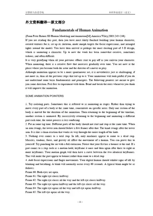
外文资料翻译—原文部分Fundamentals of Human Animation(From Peter Ratner.3D Human Modeling and Animation[M].America:Wiley,2003:243~249)If you are reading this part, then you have most likely finished building your human character, created textures for it, set up its skeleton, made morph targets for facial expressions, and arranged lights around the model. You have then arrived at perhaps the most exciting part of 3-D design, which is animating a character. Up to now the work has been somewhat creative, sometimes tedious, and often difficult.It is very gratifying when all your previous efforts start to pay off as you enliven your character. When animating, there is a creative flow that increases gradually over time. You are now at the phase where you become both the actor and the director of a movie or play.Although animation appears to be a more spontaneous act, it is nevertheless just as challenging, if not more so, than all the previous steps that led up to it. Your animations will look pitiful if you do not understand some basic fundamentals and principles. The following pointers are meant to give you some direction. Feel free to experiment with them. Bend and break the rules whenever you think it will improve the animation.SOME ANIMATION POINTERS1. Try isolating parts. Sometimes this is referred to as animating in stages. Rather than trying to move every part of a body at the same time, concentrate on specific areas. Only one section of the body is moved for the duration of the animation. Then returning to the beginning of the timeline, another section is animated. By successively returning to the beginning and animating a different part each time, the entire process is less confusing.2. Put in some lag time. Different parts of the body should not start and stop at the same time. When an arm swings, the lower arm should follow a few frames after that. The hand swings after the lower arm. It is like a chain reaction that works its way through the entire length of the limb.3. Nothing ever comes to a total stop. In life, only machines appear to come to a dead stop. Muscles, tendons, force, and gravity all affect the movement of a human. You can prove this to yourself. Try punching the air with a full extension. Notice that your fist has a bounce at the end. If a part comes to a stop such as a motion hold, keyframe it once and then again after three to eight or more keyframes. Your motion graph will then have a curve between the two identical keyframes. This will make the part appear to bounce rather than come to a dead stop.4. Add facial expressions and finger movements. Your digital human should exhibit signs of life by blinking and breathing. A blink will normally occur every 60 seconds. A typical blink might be as follows:Frame 60: Both eyes are open.Frame 61: The right eye closes halfway.Frame 62: The right eye closes all the way and the left eye closes halfway.Frame 63: The right eye opens halfway and the left eye closes all the way.Frame 64: The right eye opens all the way and left eye opens halfway.Frame 65: The left eye opens all the way.Closing the eyes at slightly different times makes the blink less mechanical.Changing facial expressions could be just using eye movements to indicate thoughts running through your model's head. The hands will appear stiff if you do not add finger movements. Too many students are too lazy to take the time to add facial and hand movements. If you make the extra effort for these details you will find that your animations become much more interesting.5. What is not seen by the camera is unimportant. If an arm goes through a leg but is not seen in the camera view, then do not bother to fix it. If you want a hand to appear close to the body and the camera view makes it seem to be close even though it is not, then why move it any closer? This also applies to sets. There is no need to build an entire house if all the action takes place in the living room. Consider painting backdrops rather than modeling every part of a scene.6. Use a minimum amount of keyframes. Too many keyframes can make the character appear to move in spastic motions. Sharp, cartoonlike movements are created with closely spaced keyframes. Floaty or soft, languid motions are the result of widely spaced keyframes. An animation will often be a mixture of both. Try to look for ways that will abbreviate the motions. You can retain the essential elements of an animation while reducing the amount of keyframes necessary to create a gesture.7.Anchor a part of the body. Unless your character is in the air, it should have some part of itself locked to the ground. This could be a foot, a hand, or both. Whichever portion is on the ground should be held in the same spot for a number of frames. This prevents unwanted sliding motions. When the model shifts its weight, the foot that touches down becomes locked in place. This is especially true with walking motions.There are a number of ways to lock parts of a model to the ground. One method is to use inverse kinematics. The goal object, which could be a null, automatically locks a foot or hand to the bottom surface. Another method is to manually keyframe the part that needs to be motionless in the same spot. The character or its limbs will have to be moved and rotated, so that foot or hand stays in the same place. If you are using forward kinematics, then this could mean keyframing practically every frame until it is time to unlock that foot or hand.8.A character should exhibit weight. One of the most challenging tasks in 3-D animation is to have a digital actor appear to have weight and mass. You can use several techniques to achieve this. Squash and stretch, or weight and recoil, one of the 12 principles of animation discussed in Chapter 12, is an excellent way to give your character weight.By adding a little bounce to your human, he or she will appear to respond to the force of gravity. For example, if your character jumps up and lands, lift the body up a little after it makes contact. For a heavy character, you can do this several times and have it decrease over time. This will make it seem as if the force of the contact causes the body to vibrate a little.Secondary actions, another one of the 12 principles of animation discussed in Chapter 12, are an important way to show the effects of gravity and mass. Using the previous example of a jumping character, when he or she lands, the belly could bounce up and down, the arms could have some spring to them, the head could tilt forward, and so on.Moving or vibrating the object that comes in contact with the traveling entity is another method for showing the force of mass and gravity. A floor could vibrate or a chair that a person sits in respond to the weight by the seat going down and recovering back up a little. Sometimes an animator will shake the camera to indicate the effects of a force.It is important to take into consideration the size and weight of a character. Heavy objects such as an elephant will spend more time on the ground, while a light character like a rabbit will spendmore time in the air. The hopping rabbit hardly shows the effects of gravity and mass.9. Take the time to act out the action. So often, it is too easy to just sit at the computer and try to solve all the problems of animating a human. Put some life into the performance by getting up and acting out the motions. This will make the character's actions more unique and also solve many timing and positioning problems. The best animators are also excellent actors. A mirror is an indispensable tool for the animator. Videotaping yourself can also be a great help.10. Decide whether to use IK, FK, or a blend of both. Forward kinematics and inverse kinematics have their advantages and disadvantages. FK allows full control over the motions of different body parts. A bone can be rotated and moved to the exact degree and location one desires. The disadvantage to using FK is that when your person has to interact within an environment, simple movements become difficult. Anchoring a foot to the ground so it does not move is challenging because whenever you move the body, the feet slide. A hand resting on a desk has the same problem.IK moves the skeleton with goal objects such as a null. Using IK, the task of anchoring feet and hands becomes very simple. The disadvantage to IK is that a great amount of control is packed together into the goal objects. Certain poses become very difficult to achieve.If the upper body does not require any interaction with its environment, then consider a blend of both IK and FK. IK can be set up for the lower half of the body to anchor the feet to the ground, while FK on the upper body allows greater freedom and precision of movements.Every situation involves a different approach. Use your judgment to decide which setup fits the animation most reliably.11. Add dialogue. It has been said that more than 90% of student animations that are submitted to companies lack dialogue. The few that incorporate speech in their animations make their work highly noticeable. If the animation and dialogue are well done, then those few have a greater advantage than their competition. Companies understand that it takes extra effort and skill tocreate animation with dialogue.When you plan your story, think about creating interaction between characters not only on a physical level but through dialogue as well. There are several techniques, discussed in this chapter, that can be used to make dialogue manageable.12. Use the graph editor to clean up your animations. The graph editor is a useful tool that all 3-D animators should become familiar with. It is basically a representation of all the objects, lights, and cameras in your scene. It keeps track of all their activities and properties.A good use of the graph editor is to clean up morph targets after animating facial expressions. If the default incoming curve in your graph editor is set to arcs rather than straight lines, you will most likely find that sometimes splines in the graph editor will curve below a value of zero. This can yield some unpredictable results. The facial morph targets begin to take on negative values that lead to undesirable facial expressions. Whenever you see a curve bend below a value of zero, select the first keyframe point to the right of the arc and set its curve to linear. A more detailed discussion of the graph editor will be found in a later part of this chapter.ANIMATING IN STAGESAll the various components that can be moved on a human model often become confusing if you try to change them at the same time. The performance quickly deteriorates into a mechanical routine if you try to alter all these parts at the same keyframes. Remember, you are trying to create humanqualities, not robotic ones.Isolating areas to be moved means that you can look for the parts of the body that have motion over time and concentrate on just a few of those. For example, the first thing you can move is the body and legs. When you are done moving them around over the entire timeline, then try rotating the spine. You might do this by moving individual spine bones or using an inverse kinematics chain. Now that you have the body moving around and bending, concentrate on the arms. If you are not using an IK chain to move the arms, hands, and fingers, then rotate the bones for the upper and lower arm. Do not forget the wrist. Finger movements can be animated as one of the last parts. Facial expressions can also be animated last.Example movies showing the same character animated in stages can be viewed on the CD-ROM as CD11-1 AnimationStagesMovies. Some sample images from the animations can also be seen in Figure 11-1. The first movie shows movement only in the body and legs. During the second stage, the spine and head were animated. The third time, the arms were moved. Finally, in the fourth and final stage, facial expressions and finger movements were added.Animating in successive passes should simplify the process. Some final stages would be used to clean up or edit the animation.Sometimes the animation switches from one part of the body leading to another. For example, somewhere during the middle of an animation the upper body begins to lead the lower one. In a case like this, you would then switch from animating the lower body first to moving the upper part before the lower one.The order in which one animates can be a matter of personal choice. Some people may prefer to do facial animation first or perhaps they like to move the arms before anything else. Following is a summary of how someone might animate a human.1. First pass: Move the body and legs.2. Second pass: Move or rotate the spinal bones, neck, and head.3. Third pass: Move or rotate the arms and hands.4. Fourth pass: Animate the fingers.5. Fifth pass: Animate the eyes blinking.6. Sixth pass: Animate eye movements.7. Seventh pass: Animate the mouth, eyebrows, nose, jaw, and cheeks (you can break these up into separate passes).Most movement starts at the hips. Athletes often begin with a windup action in the pelvic area that works its way outward to the extreme parts of the body. This whiplike activity can even be observed in just about any mundane act. It is interesting to note that people who study martial arts learn that most of their power comes from the lower torso.Students are often too lazy to make finger movements a part of their animation. There are several methods that can make the process less time consuming.One way is to create morph targets of the finger positions and then use shape shifting to move the various digits. Each finger is positioned in an open and fistlike closed posture. For example, the sections of the index finger are closed, while the others are left in an open, relaxed position for one morph target. The next morph target would have only the ring finger closed while keeping the others open. During the animation, sliders are then used to open and close the fingers and/or thumbs. Another method to create finger movements is to animate them in both closed and open positions and then save the motion files for each digit. Anytime you animate the same character, you can load the motions into your new scene file. It then becomes a simple process of selecting either the closed or the open position for each finger and thumb and keyframing them wherever you desire.DIALOGUEKnowing how to make your humans talk is a crucial part of character animation. Once you add dialogue, you should notice a livelier performance and a greater personality in your character. At first, dialogue may seem too great a challenge to attempt. Actually, if you follow some simple rules, you will find that adding speech to your animations is not as daunting a task as one would think. The following suggestions should help.DIALOGUE ESSENTIALS1. Look in the mirror. Before animating, use a mirror or a reflective surface such as that on a CD to follow lip movements and facial expressions.2. The eyes, mouth, and brows change the most. The parts of the face that contain the greatest amount of muscle groups are the eyes, brows, and mouth. Therefore, these are the areas that change the most when creating expressions.3. The head constantly moves during dialogue. Animate random head movements, no matter how small, during the entire animation. Involuntary motions of the head make a point without having to state it outright. For example, nodding and shaking the head communicate, respectively, positive and negative responses. Leaning the head forward can show anger, while a downward movement communicates sadness. Move the head to accentuate and emphasize certain statements. Listen to thewords that are stressed and add extra head movements to them.4. Communicate emotions. There are six recognizable universal emotions: sadness, anger, joy, fear, disgust, and surprise. Other, more ambiguous states are pain, sleepiness, passion, physical exertion, shyness, embarrassment, worry, disdain, sternness, skepticism, laughter, yelling, vanity, impatience, and awe.5. Use phonemes and visemes. Phonemes are the individual sounds we hear in speech. Rather than trying to spell out a word, recreate the word as a phoneme. For example, the word computer is phonetically spelled "cumpewtrr." Visemes are the mouth shapes and tongue positions employed during speech. It helps tremendously to draw a chart that recreates speech as phonemes combined with mouth shapes (visemes) above or below a timeline with the frames marked and the sound and volume indicated.6. Never animate behind the dialogue. It is better to make the mouth shapes one or two frames before the dialogue.7. Don't overstate. Realistic facial movements are fairly limited. The mouth does not open that much when talking.8. Blinking is always a part of facial animation. It occurs about every two seconds. Different emotional states affect the rate of blinking. Nervousness increases the rate of blinking, while anger decreases it.9. Move the eyes. To make the character appear to be alive, be sure to add eye motions. About 80% of the time is spent watching the eyes and mouth, while about 20% is focused on the hands and body.10. Breathing should be a part of facial animation. Opening the mouth and moving the head back slightly will show an intake of air, while flaring the nostrils and having the head nod forward a little can show exhalation. Breathing movements should be very subtle and hardly noticeable...外文资料翻译—译文部分人体动画基础(引自Peter Ratner.3D Human Modeling and Animation[M].America:Wiley,2003:243~249)如果你读到了这部分,说明你很可能已构建好了人物角色,为它创建了纹理,建立起了人体骨骼,为面部表情制作了morph修改器并在模型周围安排好了灯光。

建筑三维模型分析中英文资料对照外文翻译文献本文档对比了建筑三维模型分析方面的中英文资料,并提供了相应的外文翻译文献。
以下是对比内容:1. 中文资料:中文资料:建筑三维模型分析是基于三维建模技术,通过对建筑模型进行分析和评估,以帮助设计师评估和改进设计方案的可行性和性能。
这些模型可以用于预测建筑物的能源效率、结构强度、照明效果等方面的性能。
2. 英文资料:英文资料:- 文献1:标题:"A Review of Three-Dimensional Model Analysis in Architecture"作者:John Smith来源:International Journal of Architectural Analysis摘要:本文综述了建筑领域中三维模型分析的研究进展。
通过分析现有文献,总结了三维模型分析在建筑设计中的应用、方法和技术。
文章还讨论了目前存在的挑战和未来的研究方向。
- 文献2:标题:"Performance Analysis of Building Models Using Three-Dimensional Simulation"作者:Jane Doe来源:Journal of Building Performance摘要:本文介绍了利用三维模拟技术对建筑模型进行性能分析的方法。
通过模拟建筑物在不同环境条件下的行为,提供了对建筑物能源效率、照明效果和空气流动等方面性能的评估。
文章还讨论了如何利用这些分析结果来优化建筑设计。
3. 外文翻译文献:外文翻译文献:- 文献1:《建筑中三维模型分析的综述》- 翻译摘要:本文综述了建筑领域中三维模型分析的研究进展。
通过分析现有文献,总结了三维模型分析在建筑设计中的应用、方法和技术。
文章还讨论了目前存在的挑战和未来的研究方向。
翻译摘要:本文综述了建筑领域中三维模型分析的研究进展。
通过分析现有文献,总结了三维模型分析在建筑设计中的应用、方法和技术。

毕业设计(论文)英文资料翻译MECHANISMS AND MACHINETHEORY学院:西北工业大学明德学院专业:飞行器制造工程班级: 164903班姓名:康宇鹏学号: 091773指导老师:侯伟2013年 6 月附录1 外文原文T he different approaches can be classified as the simulation with replaced models and the co-simulation of the dynamic behaviour. The simulation with replaced models uses either analogue models of the control loop for the FEA-Model of the structure or analogue models of the mechanics for the simulation of the control loop [48].In the context of the co-simulation, two independent simulation environments, one for the control loops and one for he machine structure, are coupled via interfaces duringthe simulation [33], [48], [73], [131].Within the research project MECOMAT (FP5 Growth Programme of the European Union) [103] an computer aided engineering tool was developed for the mechatronic design of machine tools, which supports the conceptual design as well as the detailed verification. The different approaches will be explained with some examples within the next sections.2.6.1 Coupled rigid multi-body simulationThe rigid coupled multi-body simulation can be used to simulate the kinematic behaviour of the machine tool while considering the control loops of the drives [20], [76], [125]. The models of the structural components are stiff and cannot deform under load, and are connected by idealised joints. The simulation is valid for any possible position of the machine tool in the workspace. Therefore it is possible to simulate positioning operations in the workspace with this approach.Pritschow et al. [73], [74], [75] developed a simulation environment which is illustrated in Figure 12. The environment was developed for the coupled simulation of a rigid multi-body model and control loop models of a PKM machine tool.Figure 12: Coupled simulation of a rigid multi-body model and control loop models of a PKM machine tool.The multi-body model of the machine tool is imported with the aid of an interface from the CAD-system into the MBS-environment. This approach enables the update of the model during the different design stages; if the layout is detailed during the design process these changes caneasily be included [74].The model is coupled with models of the control loop for each drive. The displacement and velocity of the measuring systems in the model as well as the forces of the drives are exchanged with the aid of interfaces between the MBS-environment and the Computer-Aided-Control- Engineering program. In addition the control loop models are coupled with a PC-based model of the numerical control, which generates the desired feed rate of each individual drive.Especially in the field of machine tools with parallel kinematics the possibility to perform test runs of the numerical control before implementing new functionalities, like algorithms for path preparation, collision checks or coordinate transformations into the real machines is a significant improvement to avoid physical damage [75].Rehsteiner et al. [83] used the multi body simulation to optimise the accuracy of machine tools under acceleration loads for the demands of high-speed-machining.Neugebauer et al. [71] developed models to describe the interaction of machine and hydraulic drive system of forming machines. The methods use numerical simulations for the hydraulic systems.2.6.2 Coupled Finite-Element simulationAnother approach is the coupled Finite-Element simulation with reduced models of the control loops of the drives. Within this procedure the reduced stiffness, damping and mass of the drive system are calculated with the help of a digitalblock-simulation and modelled with special elements in the FEA-model [20], [48], [76], [131].Some FEA-programs provide special linear control elements to represent the analogue model of the control loops. In this case only the settings of the controllers have to be specified as parameters of the elements in the FEAmodel[17]. These kinds of elements are handled in the same way as conventional finite elements.The simulation of the dynamic behaviour of the x-slide of a turning centre with a linear direct drive is depicted in the following Figure 13 [20]. To simulate the error at the toolcentre-point during a positioning, a trajectory profile was generated as an input signal for the controller element. The signal of the measuring system was used as an additional input signal. This signal was measured between two nodes at the two parts to which the measuring system is mounted on the real machine. At each simulationstep of the dynamic analysis the controller element calculated the force of the linear direct drive which was applied as a pair of forces (action=reaction) on the primary and the secondary parts.Figure 13: Coupled FEA-simulation with control loopsThis approach enabled the investigation of the influence of the position of the measuring system as well as different orientations of the linear direct drive. Thus the designer was able to optimise the drive of the x-slide in an early design stage and minimise the occurring errors during machining.Such changes of the principle design would be extremelyexpensive if they had to be realised at a physical prototype,or impossible if the surrounding design space didnot allow such changes.Berkemer [16], [17], [18] demonstrated the industrial use of the methodology for tuning of the SIEMENS controllers in a virtual environment, as well as recommending the modification of the machine tool dimensions to minimize inertial excitation of the machine during high speed contouring where large accelerations occur.Van Brussel et al. [104], [105] proposed to treat the complete machine tool and control as an integrated mechatronics design system. The Finite-Element-Model of the machine tool and control algorithms are integrated in the simulation environment as shown in Figure 14.The aim of the strategy is to optimise the machine tool’s mechanical components as well as the control laws during the design stage of the machine tool simultaneously.Figure 14: Integration of structural and controller modelsZäh et al. [130], [131], [132] developed a Finite-Element- Model of the feed drive and simulated the performance of the axis control law under the influence of structural vibrations received by the position sensor.2.6.3 Coupled flexible multi-body simulationThe coupled flexible multi-body simulation is used to simulate the dynamic behaviour of the machine taking into account the behaviour of the control loops of the drives [48], [80], [115]. The models of the single components of the machine tool can represent the static as well as the dynamic behaviour and are coupled by flexible connectors. In reality, guiding systems and bearings appear as joints between the components. These joints are approximated by spring-damper-elements in the flexible multi-body model. For example, for each guide shoe between two structural components one spring-damper element with stiffness and damping values in the X, Y and Z-direction is defined.To consider the influence of the individual drives of the machine tool on the dynamic behaviour, the flexible multibody model is coupled with a model of the control loops via an interface [14], [115], [126].Different research activities in the field of coupled flexible multi-body simulation have been done by Reinhart et al. [14], [80], Weck et al. [108], [109], [110], [115], [116], [126], Großmann et al. [47], [49], Denkena et al. [33], [34] ,[100] and Turna .The model set-up as well as the different types of simulations are discussed in the next sections.2.6.3.1 Model configurationEach structural component of the machine tool is modeled as a so-called flexible body [31], [115], [116]. The different elements which are used to connect the structural components, such as guiding systems, mounting devices orball-screw-drives, are modelled as a combination of flexible connectors and joints depending on the specific configuration [14].The individual flexible components of the multi-body model are connected by these flexible connectors depending on the direction of the internal force of the component (1D-element or 3D-element). The different model techniques of the different connectors in multi-body models are pictured in Figure 15.Some typical modelling techniques of popular machine components are specified below.Mounting devicesIn most technical applications the machine tool is mounted with special mounting devices onto the foundation. The stiffness and the damping in three directions have a strong influence on the dynamic behaviour of the machine tool. These components are modelled by three dimensional spring-damper-elements [126].Guiding systemsThe guiding systems are used to determine a defined movement of different machine components relative to each other. Guiding systems are also modelled by3Dspring-damper-elements. Parameters of these elements are the stiffness in two directions, perpendicular and transverse to the direction of movement. The stiffness in the direction of movement is nearly zero. The damping of such a guiding system is considered in three directions [126], [14].Figure 15: Model configuration for the flexible MBS.Ball-screw-drivesThese drives are used to realise translational movement of machine axes. Different components are used in such a drive system. The bearings and the ball screw-nut are modelled with 3D-spring-damper-elements with stiffness and damping parameters in all directions. The screw is modelled using flexible beam elements, which are able to rotate about the pitch attitude. The rotation of the screw, which is caused by the model of the servodrive in the control model, is transformed into a translational movement by the use of a nut. Thus it is possible to simulate the dynamic behaviour of such systems [113], [115],[116].2.6.3.2 Generation of flexible multi-bodiesTo consider the flexibility of the machine components during the multi-body simulation, data from natural vibration and deformation calculations of the individual components, the so-called Superelement Creation, are integrated in the multi-body model through an interface of the multi-body simulation program to popularFinite-Element- Programs [14], [76], [115] [116].Superelement Creation uses a Finite-Element-Model to define a component of a complex structure, and a connection degree of freedom set (DOF) to specify the interface nodes, or attachment points, of the component to other components of the structural system and points where forces are applied. The software calculates fixed normal modes and static constraint modes to approximate the general behaviour of the component at those “interface node degrees of freedom”.The fixed normal modes contain the dynamic response of the superelement when all “connection degrees of freedom” are fixed. The static constraint modes contain the static response assumed by the component when one degree of freedom of one interface point is given a unit deflection while fixing all other “interface degrees of freedom”. The solver perf orms Superelement Creation much like normal modes analysis using the Lanczos method, then uses the Craig-Bampton method to generate the superelement [31].The different modes of a super-element creation are illustrated in Figure 16.Figure 16: The Craig-Bampton theorem for the flexiblemulti-body simulation.For the Craig-Bampton (CB) solution option, processing concludes at this point; the reduced mass and stiffness matrices as well as the fixed normal modes and static constraint modes are stored in an output file for the interface to the multi-body simulation program.Tönshoff et al. [100] developed an alternative approach to model the elasto-kinetic behaviour of machine tool structures based on the theory of flexible multi-bodies.2.6.3.3 Coupling of multi-body models with control loopsTo consider the dynamic behaviour of the control loop a coupling to commercial Computer-Aided-Control-Engineering (CACE) programs is possible with common multibody simulation programs [34], [48], [110].Especially for machines with linear direct drives, where no mechanical transfer elements occur, the consideration of the control loops is necessary for the approximation of the drive system stiffness [108], [110], [126]. The drive control loops generated in the CACE environment can communicate with the complete machine model in the multi-body system.Figure 17 depicts the general structure of this coupling for the coupled flexible multi-body simulation of machine tools.Figure 17: Coupling of flexible multi-boidy models and control loops.The entire control system (incl. all non-linearities) delivers the resulting drive power of each axis to the multi-body system. The control loop itself is closed with the help of the velocities and displacements of the axes determined from the multi-body system.2.6.3.4 Results of the coupled flexible multi-body simulationFor the simulation of flexibility frequency response functions of the coupled flexible multi-body model, an excitation signal must additionally be defined. For this purpose, so-called INPUTS and OUTPUTS have to be generated. In the INPUT, a value is controlled from the outside for each time step during the calculation. Through the OUTPUT that can be applied as a force in the X-, Y- and Z-direction at any location of the multi-body model, the outer signal is directed into the structure [14], [47], [108], [110], [115], [126].In case of machine tools an excitation at the machining interface (tool centre point) is useful, because it corresponds to the method for experimental investigations and best depicts the excitation through machining forces in the chip removal process [108], [114], [115]. Basically, sinus wobbles, noise or an impulse are considered as excitation signal types [114].These frequency response functions are useful for the estimation of the interaction between the mechanical structure and the control during the design stage, as well as for the estimation of the influence of the controller parameters on the dynamic behaviour at the tool centre point [126], see Figure 18.\ Figure 18: Simulated frequency response functionEspecially for machine tools with small workspace dimensions, the potential of the installed drive power can only be used efficiently at high jerk settings. To optimise the dynamic behaviour of machine tools the coupled flexible multi-body simulation can be used to analyse the maximum jerk settings of the feed drives. Therefore an inputsignal for the control loops of the drives can be generated by a virtual controller.The simulation of such a positioning operation is illustratedin Figure19.Fig ure 19: Simulation of a positioning operationThe influence of the jerk on the path deviation during a positioning operation was investigated in this case. The desired path of the Z-unit was generated by a model of the controller and used as an input-signal for the control loop of the z-axis with different jerk settings. The z-unit started at standstill and was accelerated to the maximum speed of the z-drive. After a short movement with constant velocity the drive was decelerated to standstill. The results of this simulation are shown in Figure 20.Figure 20: Simulation results of a positioning operation.Such positioning operations always excite natural frequencies of the machine tool, which can lead to deviations of the desired tolerances of the workpiece or even to damaged tools dependent on the amplitude of the vibration [14], [108], [110], [126].The evaluation of the simulated vibration signals enables the allocation of the excited natural frequencies and the derivation of arrangements for improvements during the design process.2.7 Validation and optimisation of the simulation modelsDespite the rapid development of the available software tools in recent years, the correct estimation of the simulation parameters is still a problem, which limits the accuracy of the results [107].The prediction of stiffness and especially of the damping characteristics of machine components is extremely difficult due to their dependence on many different influences, like lubrication, pre-loads or tolerances [53], [68]. Measurements of the dynamic behaviour of similar machine tools or components and the validation of existing simulation models can help to find better initial values for future simulations.The measurement of the dynamic properties of machine tools usually targets two characteristics [111]:• The Frequency Response Function (FRF) of the compliance at the tool centre point (TCP)• The mode shapes of the machine with their associated resonance frequencies and dynamic amplitudes as well as the phase shift.Both characteristics can be measured with special experiments as depicted in Figure 21 for the FRF measurement. For the determination of the FRF, the TCP is excited with a dynamic actuator and the reaction of the TCP is measured. Via Fast Fourier Transformation (FFT), a frequency spectrum or a locus curve can be generated.The results of both examinations can help the design engineer to validate the simulation models in order to find realistic values for the stiffness and damping behaviour of the machine components. Design modifications to improve weak points of the machine can be assessed analytically before they are implemented in the current design or in the next machine generation.Figure 21: Measuring of a frequency response functionThe calibration of simulation models, especially the parameters ofspring-damper-elements (stiffness- and damping-coefficients) is extremely difficult and very timeconsuming. For the described example of the machine tool in Figure 15 the flexible multi-body model contains 48 different parameters to model the mounting devices, the guiding systems, different bearings and the mechanical components of theball screw drive. It is obvious that a manual calibration of such complex simulation models of machine tools is nearly impossible.Witt and Brecher [24] developed an approach for an automated optimisation of simulation models with the help of measured frequency response functions. To match the results of the simulation and the measuring it is possible to model the stiffness and damping parameters as design variables and optimise them by using numerical optimization methods, e.g sequential quadratic programming (SQP). The design goal of this optimisation is the minimization of the deviation of the measured and the simulated frequency response function.The principle approach of this optimisation is illustrated inthe following Figure 22.Figure 22: Automated model update with measured frequency response functions.附录2 中文翻译动态结构和回路控制可按不同的方法可以分为模型替换模拟和动态性能(特性)联合模拟。
三维目标英语模板作文英文回答:3D Objects in English。
3D objects are objects that have three dimensions: length, width, and height. They can be physical objects, such as a ball or a cube, or they can be digital objects, such as a 3D model or a video game character.3D objects are often used in engineering, design, and manufacturing. They can also be used in entertainment, such as in movies and video games.There are many different ways to create 3D objects. One common method is to use a 3D scanner to create a digital model of a physical object. Another method is to use a 3D modeling software program to create a digital model from scratch.Once a 3D model has been created, it can be used to create a physical object using a 3D printer. 3D printerscan create objects from a variety of materials, including plastic, metal, and ceramic.3D objects are becoming increasingly popular as the technology continues to improve. They are used in a wide variety of applications, from engineering to entertainment. As the technology continues to develop, we can expect tosee even more innovative and exciting uses for 3D objectsin the future.中文回答:三维目标。
Image-based 3D modeling methodAbstractThree-dimensional reconstruction is a basic research question of computer graphics and computer vision. In real life, 3D model reconstruction is widely used in object recognition, industrial automatic design, video games, animation, restore the original appearance of buildings and so on, while a higher reconstruction efficiency required to achieve real-time calculation .However, using software (such as 3D MAX and Maya, etc.) construct three-dimensional model by hand is a very tedious and costly work. Therefore, studying how obtain three-dimensional model directly and quickly from the real world, become a hot issue in the field.Realistic three-dimensional reconstruction is divided into active and passive methods. Active method is represented by three-dimensional scanner method. Passive method is that two-dimensional image-based three-dimensional reconstruction.Image-based 3D modeling method which has low cost, flexible and directly get the color texture, can reconstruct three-dimensional model fast and realistic. Image-based three-dimensional reconstruction is a significant work, there are automatic three-dimensional reconstruction, but reconstruction result is not satisfactory. We think that the user can interact with system, add some shape editing and increase flexibility of the system, but too many human-computer interaction will increase burden to the end user. Therefore, this work is mainly devoted to manually add the interaction of three-dimensional reconstruction of the building systems, design the corresponding algorithm to reduce end user workload.The main contributions are the following:1 .Present a building reconstruction and modeling system which allows noviceusers to create textured polygonal models from a set of photographs of a building.2. At present, the extracted information contains too many inconsistencies, missing features, and unwanted noise to be completely reliable. Therefore, we aim at creating a semi-automatic solution which helps reduce steps in footprint drawing process and increase the accuracy of the result.3. Exacting building footprint from point cloud. We have designed an algorithm to predict the continuation of a user-traced line segment, and provided visual cue to assist the drawing process. As the user moves the mouse, the system displays corresponding points in the image to help the user draw the first line segment.Once the first line segment is drawn, the system, given a set of adaptive parameters, uses Hough transform and least-square fitting methods to automatically deduce subsequent line er can then opt to confirm or reject the deduced line segments.Keywords:Image-based 3D Reconstruction; 3D Model;Point Cloud; Building Footprint基于图像的三维重建摘要三维模型获取是计算机视觉和计算机图形学领域的一个基本研究问题。
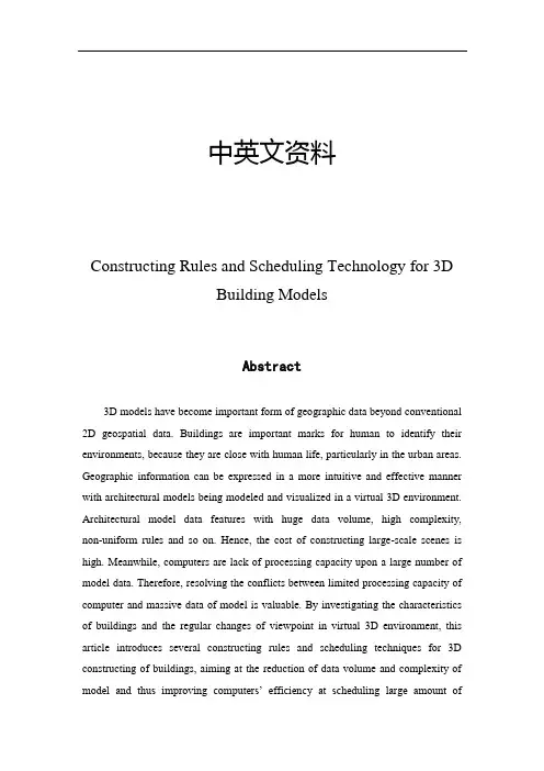
中英文资料Constructing Rules and Scheduling Technology for 3DBuilding ModelsAbstract3D models have become important form of geographic data beyond conventional 2D geospatial data. Buildings are important marks for human to identify their environments, because they are close with human life, particularly in the urban areas. Geographic information can be expressed in a more intuitive and effective manner with architectural models being modeled and visualized in a virtual 3D environment. Architectural model data features with huge data volume, high complexity, non-uniform rules and so on. Hence, the cost of constructing large-scale scenes is high. Meanwhile, computers are lack of processing capacity upon a large number of model data. Therefore, resolving the conflicts between limited processing capacity of computer and massive data of model is valuable. By investigating the characteristics of buildings and the regular changes of viewpoint in virtual 3D environment, this article introduces several constructing rules and scheduling techniques for 3D constructing of buildings, aiming at the reduction of data volume and complexity of model and thus improving computers’ efficiency at scheduling large amount ofarchitectural models. In order to evaluate the efficiency of proposed constructing rules and scheduling technology listed in the above text, the authors carry out a case study by 3D constructing the campus of Peking University using the proposed method and the traditional method. The two results are then examined and compared from aspects of model data volume, model factuality, speed of model loading, average responding time during visualization, compatibility and reusability in 3D geo-visualization platforms: China Star, one China’s own platform for 3D g lobal GIS manufactured by the authors of this paper. The result of comparison reveals that models built by the proposed methods are much better than those built using traditional methods. For the constructing of building objects in large-scale scenes, the proposed methods can not only reduce the complexity and amount of model data remarkably, but can also improving computers’ efficiency.Keywords:Constructing rules, Model scheduling, 3D buildingsI. INTRODUCTIONIn recent years, with the development of 3D GIS (Geographical Information System) software like Google Earth, Skyline, NASA World Wind, large-scale 3D building models with regional characteristics have become important form of geographic data beyond conventional 2D geospatial data, like multi-resolution remote sensing images and vector data [1].Compared to traditional 2D representation, geographic information can be expressed in a more intuitive and effective manner with architectural models being modeled and visualized in a virtual 3D environment. 3D representation and visualization provides better visual effect and vivid urban geographic information, and thus plays an important role in people's perceptions of their environment. Meanwhile, the 3D building data is also of great significance for the construction of digital cities.But how to efficiently visualize thousands of 3D building models in a virtual 3D environment is not a trivial question. The most difficult part of the question is the conflicts between limited processing capacity of computer and massive volume of model data, particularly in the procedure of model rendering. Taking the 3D modeling of a city for the example using traditional 3D modeling method, suppose there are 100 000 buildings to model in the urban area and the average size of model data for each building is roughly 10 M. So the total data volume of building models in the city could reach a TB level. However, the capacity of ordinary computer memory is only in the GB scale. Based on this concern, the authors proposed the scheduling technology for large-scale 3D buildings models in aspects of model loading and rendering. Due to the lack of building constructing rules and standard, models of buildings vary in aspects of constructing methods, textures collection and model data volume, especially in aspects of model reusability and factuality. Such a large amount of data without uniform constructing rules becomes a huge challenge for data storage, processing and visualization in computers. It also brings the problem of incompatibility among different 3D GIS systems.After years of research in GIS (Geographic Information System), people have accumulated a number of ways to solve the above problems [3]. However in virtual 3D environment, because of the difference in data organization and manners of human computer interaction (HCI), we need to apply a new standardized method of modeling and scheduling for 3D models. At present, there is no such a uniform method as the constructing specification or standard for the modeling of 3D buildings. Existing approaches are insufficient and inefficient in the scheduling of large-scale building models, resulting in poor performance or large memory occupancy. In response to such questions, the authors proposed a new method for the construction of 3D building models. Models built using the proposed methods could be much better than those built using traditional methods. For the 3D modeling of building objects in scenes of large scale, the proposed methods can not only remarkably reduce the complexity and amount of model data, but can also improving the reusability and factuality of models. Concerning the scheduling of large-scale building models, the Model Loading Judgment Algorithm (MLJA) proposed in this paper could solve the optimal judgment problem of model loading in 3D vision cone, particularly in circumstance with uncertain user interactions.This paper first examines and analyzes existing problems in constructing and scheduling steps of 3D building models. Then the authors propose a set of constructing rules for 3D building models together with methods of model optimization. Besides, special scheduling technology and optimization method for model rendering is also applied in this paper for large-scale 3D building models. In order to evaluate the efficiency of proposed rules and methods, a case study is undertaken by constructing a 3D model for the main campus of Peking University and Shenzhen using both the proposed method and the traditional method respectively. The two resulting 3D models of Peking University campus and Shenzhen are then examined and compared with one other in aspects of model data volume, model factuality, speed of model loading, average responding time during visualization, compatibility and reusability in various 3D geo-visualization platforms like China Star (one China’s own platform for 3D global GIS manufactured by the authors),Skyline, etc. Result of comparison tells that provided similar factuality of models, using the proposed method of us, the data volume of models was reduced by 86%; the speed of model loading was increased by 70%; the average responding time of model during visualization and interaction speed was reduced by 83%. Meanwhile, the compatibility and reusability of 3D model data are also improved if they are constructed using our approach.II. MODELING RULES OF 3D BUILDINGS 3D scene is the best form of visualization for digital city systems. While constructing 3D models for buildings objects, proper methods and rules should be used, which are made with full concerns of the characteristics of 3D building models [2]. The resulting models should be robust, reusable and suitable enough for transmission over computer network, and should at the same time be automatically adapted to system capability.Generally speaking, methods of constructing 3D building models can be classified into three types: wireframe modeling, surface modeling and solid modeling. In normal circumstances, to model buildings in 3D format, the framework of building should be constructed first according to the contour features, number of floors, floor height, aerial photograph and liveaction photos of buildings. Then, gather the characteristics of scene that the buildings to model are representing. Important characteristics include buildings aerial photograph or liveaction shooting photos. Finally, map the gathered texture to model framework, optimize the model and create database of the 3D building models.Although there have already been many approaches for the construction of 3D building models, a unified modeling method and rules are still needed to improve the efficiency, quality, facilitate checking, reusability and archiving of constructed models. By investigating the characteristics of buildings, we found that buildings have regular geometric solid for modeling, similar texture on the surfaces of different directions, high similarity in small-scale models of buildings, etc. According to these, this article gives a discussion on the modeling rules from three aspects, includingconstructing rules of the 3D building models, texture mapping rules of 3D building models and optimization method for constructed models based on mentioned constructing rules.A. Constructing rules of the 3D building modelsThe 3D building modeling refers to the procedure of representing true buildings from the real world into computer in the form of 3D objects [4]. Human beings, as the creator and at the same time potential users of models, play a key role in this procedure. People are different from each other in the understanding of the building objects, methods of modeling and the software tools they use for modeling. Such differences among people who carry out modeling work at the same time lead to the 3D models of diverse quality and low efficiency. So the 3D building constructing rules proposed in this article become necessary and helpful to solve the above problems.1) Combine similar floors as a whole and keep the roof independent2) Share similar models and process the details especially3) Constructing in the unit of meters4) Define central point of the model5) Unified model codes6) Reduce number of surfaces in a single model7) Reduce combination of the models8) Rational split of modelsB. Texture mapping rules of 3D buildingsBased on the framework of 3D models, we need to attach these models with proper textures to create a better visualization effect for 3D buildings. The quality of texture mapping has a direct impact on the visual effect of the scene whiling being rendered [5]. Since the graphics card of computer will load all the textures together when rendering a model, texture mapping rules and the quality of the texture mapping can directly influence the efficiency of rendering as well.C. Optimization of models based on constructing rulesBased on constructing rules and the characteristics of 3D building models, theauthors develop a software tool to optimize the 3D building models automatically. The optimizations implemented in the software tool contain the deletion of models’ internal textures, merging adjacent vertices/lines/surfaces, removing un-mapped framework and so on. Besides, the software can enhance the shape of the whole model, texture position and model facticity in the procedure of model optimization.III. SCHEDULING TECHNOLOGY OF LARGE-SCALE 3DBUILDING MODELSFor the 3D visualization of large-scale architectural models, a series of measures could be applied to ensure the efficient rendering of models. Important measures includes the scene organization, vision cone cutting, elimination of textures on the backside of models, Shader optimization, LOD Algorithm, math library optimization, memory allocation optimization, etc..How to display thousands of 3D city buildings’ models in a virtual 3D environment is not trivial. The main problem is the scheduling of models [7]. It determines when and which models to be loaded. This problem can be divided into two smaller problems: Find visible spatial region of models in 3D environment, and optimization method of model rendering efficiency.A. Find visible spatial region of models in 3D environmentAccording to operating mechanism of computers during 3D visualization and the characteristics of large-scale 3D scene, we need to determine the position of current viewpoint first before loading signal models or urban-unit models. Then in response to the regular changes of viewpoint in virtual 3D environment, the system will preload the 3D model data into memory automatically. In this way, frequent IO operations can be reduced and thus overall efficiency of system gets improved. A new algorithm named MLJA (Model Loading Judgment Algorithm) is proposed in this paper in order to find out visible region of models in the 3D environment. The algorithm integrates the graticules and elevation information to determine the current viewpoint of users in the 3D space. And with the movement of viewpoint, the algorithm schedules the loading of model correspondingly and efficiently.B. Optimization method of model rendering efficiencyThe scheduling method of large-scale 3D building models proposed above is an effective way to solve the problem caused the contradiction between large model data volume and limited capacity of computers. According to the algorithm, we can avoid loading the whole large-scale 3D building models at one time for the sake of limited computer memory, and then improve system efficiency in the procedure of model loading and abandoning. Due to the limited capacity of GPU and local video memory, we need a further research on how to display the loaded model data in more efficient manner. In the remaining part of this paper, the authors will continue to introduce several methods on the optimization of model rendering in the vision cone.1) Elimination of textures on the backside of modelsThe backside of the 3D model is invisible to the users. If we omit the texture mapping for the 3D model on the backside, the processing load of graphic card will be reduced as much as at least 50%. Besides, according to an investigation on procedure of actual model rendering, the authors found that on the backside of the 3D model, the invisible texture is rendered in a counter-clockwise manner against the direction of eyesight, while the visible texture mapping is rendered in clockwise manner. So we can omit the rendering of models which is intended to be rendered in counterclockwise manner. Therefore, the textures won’t exist on the back of 3D models. The graphic card could then work more rapidly and efficiently.2) Eliminate the shielded modelBy calculating the geometric relationship between 3D models in the scene, the shielded models can be omitted while displaying the scene with appropriate shielding patches. Through this way, we can effectively reduce the usage of graphics card memory, and thus achieve higher rendering efficiency and faster 3D virtual system.In the virtual 3D geographic information system, we often observe 3D models from a high altitude. It is especially true for large-scale outdoor 3D models. The usual arrangement of 3D building models are always sparse, however the real block is very small. Therefore, establishing an index for visual control, which is similar to the BSP tree, doesn’t amount to much. Through carefully studying DirectX, we found that wecan take advantage of the latest Z-buffering technology of DirectX to implement the shielding control of models.3) Optimization method of the Shader instructionsIn shader 3.0 technology, SM (Shader Model) is a model which can optimize the rendering engine. A 3D scene usually contains several shaders. Among these shaders, some deal with the surfaces and skeletons of buildings, and others deal with the texture of 3D building models.Geometry can be handled quickly by shader batch process. The shader can combine similar culmination in 3D building models, deal with the correlation operation of a single vertex, determine the physical shape of the model, link the point, line, triangle and other polygons for a rapid processing while create new polygons, etc. We can assign the computing task to shader and local video memory directly in a very short time without bothering the CPU. In this case, visual effects of smoke, explosions and other special effects and complex graphics are no longer necessary to be processed by the CPU of computer. Such features of shader can speed up both the CPU and graphic card in processing huge amount of 3D models.4) LOD algorithm of large-scale 3D sceneLOD (Level of Detail) is a common and effective solution to resolve the conflicts between real time visualization and the authenticity of models [8]. By investigating the main features and typical algorithms of LOD technology, the authors proposed a new structure for dynamic multi-level display. This structure not only can be applied to the mesh simplification of models with many different but fixed topologies, but also can be applied to the mesh simplification of models with variable topology. Therefore, the LOD technology can be applied to any grid model. Based on the above concerns, the authors also design a mesh simplification algorithm for variable topology through vertices merge. Via the dual operations of vertex merging and splitting, we can achieve smooth transition across different LOD levels of models, and automatically change the model topology.These above techniques plays important role in 3D scene. It can not only enable a rapid visualization of large-scale scene, but also can provide a high-resolutiondisplay of scene at a local scale with plenty of architectural details.IV. CONCLUDING REMARKSConstructing rules and scheduling technology plays an important role in the application of large-scale 3D buildings. Since people’s demand for 3D expression brings a challenge of high-efficiency and high-quality to virtual 3D environment, the methods proposed in this article give a good try in these aspects. According to the authors’ research and case studies in this paper, integration of constructing rules and scheduling technology is promising in providing powerful tools to solve the conflicts between limited processing capacity of computer and massive data of models. The result of our case study on Peking University indicates that the proposed new method on constructing rules and scheduling technology for large-scale 3D scene is highly feasible and efficient in practice. The proposed methods can not only standardize the procedure of model construction, but also can significantly shorten the time taken in scheduling large-scale 3D buildings. It introduces a new effective way to develop applications for large-scale three-dimensional scene.构建三维建筑模型的规则和调度技术摘要三维模型已成为超越了传统的二维地理空间数据的一种重要的地理数据形式。
三维解析仿真的英语作文Three-Dimensional Computational Modeling.Three-dimensional (3D) computational modeling is the process of creating a mathematical representation of a three-dimensional object. This representation can be used to simulate the behavior of the object under different conditions. 3D computational modeling is used in a wide variety of fields, including engineering, medicine, and manufacturing.In engineering, 3D computational modeling is used to simulate the behavior of structures and machines. This information can be used to design structures that are safe and efficient. In medicine, 3D computational modeling is used to simulate the behavior of organs and tissues. This information can be used to diagnose diseases and develop new treatments. In manufacturing, 3D computational modeling is used to simulate the behavior of products during the manufacturing process. This information can be used tooptimize the manufacturing process and reduce product defects.There are many different types of 3D computational modeling software available. The type of software used will depend on the specific application. Some of the most popular 3D computational modeling software programs include ANSYS, COMSOL, and Siemens NX.3D computational modeling is a powerful tool that can be used to simulate the behavior of objects in a variety of different fields. This information can be used to design safer and more efficient structures, diagnose and treat diseases, and optimize the manufacturing process.Benefits of 3D Computational Modeling.There are many benefits to using 3D computational modeling. Some of the most notable benefits include:Increased accuracy: 3D computational models are more accurate than traditional 2D models. This is because 3Dmodels can take into account the effects of all three dimensions of space.Reduced time and cost: 3D computational modeling can save time and cost by reducing the need for physical testing. Physical testing can be expensive and time-consuming, and it is not always possible to test all possible scenarios.Improved communication: 3D computational models can be used to communicate complex designs and concepts more easily. This can help to reduce errors and improve collaboration between different teams.Applications of 3D Computational Modeling.3D computational modeling is used in a wide variety of applications, including:Engineering: 3D computational modeling is used to simulate the behavior of structures and machines. This information can be used to design structures that are safeand efficient.Medicine: 3D computational modeling is used to simulate the behavior of organs and tissues. This information can be used to diagnose diseases and develop new treatments.Manufacturing: 3D computational modeling is used to simulate the behavior of products during the manufacturing process. This information can be used to optimize the manufacturing process and reduce product defects.Future of 3D Computational Modeling.The future of 3D computational modeling is bright. As computer hardware and software continue to improve, 3D computational models will become even more accurate and sophisticated. This will open up new possibilities for using 3D computational modeling in a wide variety of applications.One of the most exciting developments in 3Dcomputational modeling is the use of artificialintelligence (AI). AI can be used to automate the process of creating and running 3D computational models. This will make it easier for engineers, scientists, and other professionals to use 3D computational modeling in their work.Another exciting development in 3D computational modeling is the use of virtual reality (VR). VR can be used to create immersive 3D environments that allow users to interact with 3D computational models. This can make it easier to understand complex designs and concepts.3D computational modeling is a powerful tool that is transforming the way we design, build, and heal. As computer hardware and software continue to improve, 3D computational modeling will become even more powerful and versatile. This will open up new possibilities for using 3D computational modeling in a wide variety of applications.。

三维建模外文资料翻译3000字外文资料翻译—原文部分Fundamentals of Human Animation(From Peter Ratner.3D Human Modeling andAnimation[M].America:Wiley,2003:243~249)If you are reading this part, then you have most likely finished building your human character, created textures for it, set up its skeleton, made morph targets for facial expressions, and arranged lights around the model. You have then arrived at perhaps the most exciting part of 3-D design, which is animating a character. Up to now the work has been somewhat creative, sometimes tedious, and often difficult.It is very gratifying when all your previous efforts start to pay off as you enliven your character. When animating, there is a creative flow that increases gradually over time. You are now at the phase where you become both the actor and the director of a movie or play.Although animation appears to be a more spontaneous act, it is nevertheless just as challenging, if not more so, than all the previous steps that led up to it. Your animations will look pitiful if you do not understand some basic fundamentals and principles. The following pointers are meant to give you some direction. Feel free to experiment with them. Bend and break the rules whenever you think it will improve the animation.SOME ANIMATION POINTERS1. Try isolating parts. Sometimes this is referred to as animating in stages. Rather than trying to move every part of a body at the same time, concentrate on specific areas. Only one section of the body is moved for the duration of the animation. Then returning to the beginning of the timeline, another section is animated. By successively returning to the beginning and animating a different part each time, the entire process is less confusing.2. Put in some lag time. Different parts of the body should not start and stop at the same time. When an arm swings, the lower arm should follow a few frames after that. The hand swings after the lower arm. It is like a chain reaction that works its way through the entire length of the limb.3. Nothing ever comes to a total stop. In life, only machines appear to come to a dead stop. Muscles, tendons, force, and gravity all affect the movement of a human. You can prove this to yourself. Try punching the air with a full extension. Notice that your fist has a bounce at the end. If a part comes to a stop such as a motion hold, keyframe it once and then again after three to eight or more keyframes. Your motion graph will then have a curve between the two identical keyframes. This will make the part appear to bounce rather than come to a dead stop.4. Add facial expressions and finger movements. Your digital human should exhibit signs of life by blinking and breathing. A blink will normally occur every 60 seconds. A typical blink might be as follows:Frame 60: Both eyes are open.Frame 61: The right eye closes halfway.Frame 62: The right eye closes all the way and the left eye closes halfway.Frame 63: The right eye opens halfway and the left eye closes all the way.Frame 64: The right eye opens all the way and left eye opens halfway.Frame 65: The left eye opens all the way.Closing the eyes at slightly different times makes the blink less mechanical.Changing facial expressions could be just using eye movements to indicate thoughts running through your model's head. The hands will appear stiff if you do not add finger movements. Too many students are too lazy to take the time to add facial and hand movements. If you make the extra effort for these details you will find that your animations become much more interesting.5. What is not seen by the camera is unimportant. If an arm goes through a leg but is not seen in the camera view, then do not bother to fix it. If you want a hand to appear close to the body and the camera view makes it seem to be close even though it is not, then why move it any closer? This also applies to sets. There is no need to build an entire house if all the action takes place in the living room. Consider painting backdrops rather than modeling every part of a scene.6. Use a minimum amount of keyframes. Too many keyframes can make the character appear to move in spastic motions. Sharp, cartoonlike movements are created with closely spaced keyframes. Floaty or soft, languid motions are the result of widely spaced keyframes. An animation will often be a mixture of both. Try to look for ways that will abbreviate the motions. You can retain the essential elements of an animation while reducing the amount of keyframes necessary to create a gesture.7.Anchor a part of the body. Unless your character is in the air, it should have some part of itself locked to the ground. This could be a foot, a hand, or both. Whichever portionis on the ground should be held in the same spot for a number of frames. This prevents unwanted sliding motions. When the model shifts its weight, the foot that touches down becomes locked in place. This is especially true with walking motions.There are a number of ways to lock parts of a model to the ground. One method is to use inverse kinematics. The goal object, which could be a null, automatically locks a foot or hand to the bottom surface. Another method is to manually keyframe the part that needs to be motionless in the same spot. The character or its limbs will have to be moved and rotated, so that foot or hand stays in the same place. If you are using forward kinematics, then this could mean keyframing practically every frame until it is time to unlock that foot or hand.8.A character should exhibit weight. One of the most challenging tasks in 3-D animation is to have a digital actor appear to have weight and mass. You can use several techniques to achieve this. Squash and stretch, or weight and recoil, one of the 12 principles of animation discussed in Chapter 12, is an excellent way to give your character weight.By adding a little bounce to your human, he or she will appear to respond to the force of gravity. For example, if your character jumps up and lands, lift the body up a little after it makes contact. For a heavy character, you can do this several times andhave it decrease over time. This will make it seem as if the force of the contact causes the body to vibrate a little.Secondary actions, another one of the 12 principles of animation discussed in Chapter 12, are an important way to show the effects of gravity and mass. Using the previous example of a jumping character, when he or she lands, the belly could bounce up and down, the arms could have some spring to them, the head could tilt forward, and so on.Moving or vibrating the object that comes in contact with the traveling entity is another method for showing the force of mass and gravity. A floor could vibrate or a chair that a person sits in respond to the weight by the seat going down and recovering back up a little. Sometimes an animator will shake the camera to indicate the effects of a force.It is important to take into consideration the size and weight of a character. Heavy objects such as an elephant will spend more time on the ground, while a light character like a rabbit will spend more time in the air. The hopping rabbit hardly shows the effects of gravity and mass.9. Take the time to act out the action. So often, it is too easy to just sit at the computer and try to solve all the problems of animating a human. Put some life into the performance by getting up and acting out the motions. This will make the character's actions more unique and also solve many timing and positioning problems. The best animators are also excellent actors. A mirror is an indispensable tool for the animator. Videotaping yourself can also be a great help.10. Decide whether to use IK, FK, or a blend of both. Forward kinematics and inverse kinematics have their advantages and disadvantages. FK allows full control over the motions of different body parts. A bone can be rotated and moved to the exact degree and location one desires. The disadvantage to using FK is that when your person has to interact within an environment, simple movements become difficult. Anchoring a foot to the ground so it does not move is challenging because whenever you move the body, the feet slide. A hand resting on a desk has the same problem.IK moves the skeleton with goal objects such as a null. Using IK, the task of anchoring feet and hands becomes very simple. The disadvantage to IK is that a great amount of control is packed together into the goal objects. Certain poses become very difficult to achieve.If the upper body does not require any interaction with its environment, then consider a blend of both IK and FK. IK can be set up for the lower half of the body to anchor the feet to the ground, while FK on the upper body allows greater freedom and precision of movements.Every situation involves a different approach. Use your judgment to decide which setup fits the animation most reliably.11. Add dialogue. It has been said that more than 90% of student animations that are submitted to companies lack dialogue. The few that incorporate speech in their animations make their work highly noticeable. If the animation and dialogue are well done, then those few have a greater advantage than their competition. Companies understand that it takes extra effort and skill tocreate animation with dialogue.When you plan your story, think about creating interaction between characters not only on a physical level but through dialogue as well. There are several techniques, discussed in this chapter, that can be used to make dialogue manageable.12. Use the graph editor to clean up your animations. The graph editor is a useful tool that all 3-D animators should become familiar with. It is basically a representation of all the objects, lights, and cameras in your scene. It keeps track of all their activities and properties.A good use of the graph editor is to clean up morph targets after animating facial expressions. If the default incoming curve in your graph editor is set to arcs rather than straight lines, you will most likely find that sometimes splines in the graph editor will curve below a value of zero. This can yield some unpredictable results. The facial morph targets begin to take on negative values that lead to undesirable facial expressions. Whenever you see a curve bend below a value of zero, select the first keyframe point to the right of the arc and set its curve to linear. A more detailed discussion of the graph editor will be found in a later part of this chapter.ANIMATING IN STAGESAll the various components that can be moved on a human model often become confusing if you try to change them at the same time. The performance quickly deteriorates into a mechanical routine if you try to alter all these parts at the same keyframes. Remember, you are trying to create human qualities, not robotic ones. Isolating areas to be moved means that you can look for the parts of the body that have motion over time and concentrate on just a few of those. For example, the first thing you can move is the body and legs. When you are done moving them around over the entire timeline, then try rotating the spine. You might do this by moving individual spine bones or using an inverse kinematics chain. Now that you have the body moving around and bending, concentrate on the arms. If you are not using an IK chain to move the arms, hands, and fingers, then rotate the bones for the upper and lower arm. Do not forget the wrist. Finger movements can be animated as one of the last parts. Facial expressions can also be animated last.Example movies showing the same character animated in stages can be viewed on the CD-ROM as CD11-1 AnimationStagesMovies. Some sample images from the animations can also be seen in Figure 11-1. The first movie shows movement only in the body and legs. During the second stage, the spine and head were animated. The third time, the arms were moved. Finally, in the fourth and final stage, facial expressions and finger movements were added.Animating in successive passes should simplify the process. Some final stages would be used to clean up or edit the animation.Sometimes the animation switches from one part of the body leading to another. For example, somewhere during the middle of an animation the upper body begins to lead the lower one. In a case like this, you would then switch from animating the lower body first to moving the upper part before the lower one.The order in which one animates can be a matter of personal choice. Some people may prefer to do facial animation first or perhaps they like to move the arms before anything else. Following is a summary of how someone might animate a human.1. First pass: Move the body and legs.2. Second pass: Move or rotate the spinal bones, neck, and head.3. Third pass: Move or rotate the arms and hands.4. Fourth pass: Animate the fingers.5. Fifth pass: Animate the eyes blinking.6. Sixth pass: Animate eye movements.7. Seventh pass: Animate the mouth, eyebrows, nose, jaw, and cheeks (you can break these up into separate passes).Most movement starts at the hips. Athletes often begin with a windup action in the pelvic area that works its way outward to the extreme parts of the body. This whiplike activity can even be observed in just about any mundane act. It is interesting to note that people who study martial arts learn that most of their power comes from the lower torso. Students are often too lazy to make finger movements a part of their animation. There are several methods that can make the process less time consuming.One way is to create morph targets of the finger positions and then use shape shifting to move the various digits. Each finger is positioned in an open and fistlike closed posture. For example, the sections of the index finger are closed, while the others are left in an open, relaxed position for one morph target. The next morph target would have only the ring finger closed while keeping the others open. During the animation, sliders are then used to open and close the fingers and/or thumbs.Another method to create finger movements is to animate them in both closed and open positions and then save the motion files for each digit. Anytime you animate the same character, you can load the motions into your new scene file. It then becomes a simple process of selecting either the closed or the open position for each finger and thumb and keyframing them wherever you desire.DIALOGUEKnowing how to make your humans talk is a crucial part of character animation. Once you add dialogue, you should notice a livelier performance and a greater personality in your character. At first, dialogue may seem too great a challenge to attempt. Actually, if you follow some simple rules, you will find that adding speech to your animations is not as daunting a task as one would think. The following suggestions should help.DIALOGUE ESSENTIALS1. Look in the mirror. Before animating, use a mirror or a reflective surface such as that on a CD to follow lip movements and facial expressions.2. The eyes, mouth, and brows change the most. The parts of the face that contain the greatest amount of muscle groups are the eyes, brows, and mouth. Therefore, these are the areas that change the most when creating expressions.3. The head constantly moves during dialogue. Animate random head movements, no matter how small, during the entire animation. Involuntary motions of the head make a point without having to state it outright. For example, nodding and shaking the head communicate, respectively, positive and negative responses. Leaning the head forward can show anger, while a downward movement communicates sadness. Move the head to accentuate and emphasize certain statements. Listen to the words that are stressed and add extra head movements to them.4. Communicate emotions. There are six recognizable universal emotions: sadness, anger, joy, fear, disgust, and surprise. Other, more ambiguous states are pain, sleepiness, passion, physical exertion, shyness, embarrassment, worry, disdain, sternness, skepticism, laughter, yelling, vanity, impatience, and awe.5. Use phonemes and visemes. Phonemes are the individual sounds we hear in speech. Rather than trying to spell out a word, recreate the word as a phoneme. For example, the word computer is phonetically spelled "cumpewtrr." Visemes are the mouth shapes and tongue positions employed during speech. It helps tremendously to draw a chart that recreates speech as phonemes combined with mouth shapes (visemes) above or below a timeline with the frames marked and the sound and volume indicated.6. Never animate behind the dialogue. It is better to make the mouth shapes one or two frames before the dialogue.7. Don't overstate. Realistic facial movements are fairly limited. The mouth does not open that much when talking.8. Blinking is always a part of facial animation. It occurs about every two seconds. Different emotional states affect the rate of blinking. Nervousness increases the rate of blinking, while anger decreases it.9. Move the eyes. To make the character appear to be alive, be sure to add eye motions. About 80% of the time is spent watching the eyes and mouth, while about 20% is focused on the hands and body.10. Breathing should be a part of facial animation. Opening the mouth and moving the head back slightly will show an intake of air, while flaring the nostrils and having the head nod forward a little can show exhalation. Breathing movements should be very subtle and hardly noticeable...外文资料翻译—译文部分人体动画基础(引自 Peter Ratner.3D Human Modeling andAnimation[M].America:Wiley,2003:243~249)如果你读到了这部分,说明你很可能已构建好了人物角色,为它创建了纹理,建立起了人体骨骼,为面部表情制作了morph修改器并在模型周围安排好了灯光。
三维建模数字化设计英语In the realm of modern design, 3D modeling has revolutionized the way we conceptualize and create. It allows designers to visualize their ideas in a tangible form,bringing innovation to life with digital precision.The process of 3D modeling starts with a concept, whichis then translated into a digital blueprint. This blueprintis the foundation upon which the model is built, layer by layer, in a virtual space.As the model takes shape, each detail is carefullycrafted to ensure accuracy and functionality. The digitaltools at our disposal offer unparalleled control over the design, enabling us to make adjustments with ease.The versatility of 3D modeling extends beyond the design phase. It is instrumental in the prototyping process,allowing for the creation of physical models that can betested and refined before production.Moreover, 3D modeling has a significant impact on the manufacturing industry. It streamlines the production process, reducing costs and time, while ensuring the highest qualityof the final product.In the field of education, 3D modeling is an invaluable tool for teaching complex concepts. It provides students witha hands-on approach to learning, enhancing their understanding and creativity.Lastly, the integration of 3D modeling in various industries, from architecture to entertainment, showcases its potential to shape the future of design and innovation. It is a testament to the power of technology in transforming the way we create and interact with the world around us.。
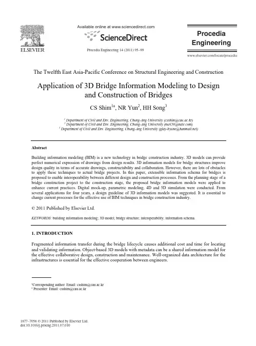
Available online at vailable online at Procedia Engineering Procedia Engineering 00 (2011) 000–000 /locate/procedia The Twelfth East Asia-Pacific Conference on Structural Engineering and ConstructionApplication of 3D Bridge Information Modeling to Designand Construction of BridgesCS Shim 1a , NR Yun 2, HH Song 31Department of Civil and Env. Engineering, Chung-Ang University (csshim@cau.ac.kr)2 Department of Civil and Env. Engineering, Chung-Ang University (nuri58@)3 Department of Civil and Env. Engineering, Chung-Ang University (glay-hyune@) AbstractBuilding information modeling (BIM) is a new technology in bridge construction industry. 3D models can provide perfect numerical expression of drawings from design results. 3D information models for bridge structures improve design quality in terms of accurate drawings, constructability and collaboration. However, there are lots of obstacles to apply these techniques to actual bridge projects. In this paper, extensible information schema for bridges is proposed to enable interoperability between different design and construction processes. From the planning stage of a bridge construction project to the construction stage, the proposed bridge information models were applied to enhance current practices. Digital mock-up, parametric modeling, 4D and 5D simulation were conducted. From several applications for four years, a design guideline of 3D information models was suggested. It is essential to change current processes for the effective use of BIM techniques in bridge construction industry.© 2011 Published by Elsevier Ltd.KEYWORDS: building information modeling; 3D model; bridge structure; interoperability; information schema.1.INTRODUCTIONFragmented information transfer during the bridge lifecycle causes additional cost and time for locating and validating information. Object-based 3D models with metadata can be a shared information model for the effective collaborative design, construction and maintenance. Well-organized data architecture for the infrastructures is essential for the effective cooperation between engineers.aCorresponding author: Email: csshim@cau.ac.kr a Presenter: Email: csshim@cau.ac.kr1877–7058 © 2011 Published by Elsevier Ltd.doi:10.1016/j.proeng.2011.07.010Procedia Engineering 14 (2011) 95–9996 C.S. Shim et al. / Procedia Engineering 14 (2011) 95–992Author name / Procedia Engineering 00 (2011) 000–000A construction project life-cycle management system was proposed for the enhancement of productivityin construction industry. Architectures of geometry and information for several bridge types were built and utilized for collaborative works. Each information layer includes necessary metadata for the data sharing and knowledge accumulation during construction project processes. This information has its own data architecture which is derived from similar concept of product breakdown structure (PBS) and work breakdown structure (WBS). The integrated information model realized a virtual construction system for bridges and dramatically increased the productivity of the whole management process. Prototypes for the bridge information model were suggested and pilot tests were conducted to evaluate their effectiveness and to derive the guidelines for the future 3D models. The applications were mainly for international bridge construction projects and for domestic bridges. Because of obstacles in practices, 3D models were utilized for specific processes in the project. Evaluated effects of the applications were summarized and a guideline of 3D model based design was proposed.2. 3D BRIDGE INFORMATION MODELFor the effective collaboration of bridge construction projects, it is essential to define architectures of the information models and information delivery manuals. WBS and OBS (organization breakdown structure) need to be connected to PBS in the construction project lifecycle management (CPLM) system.Each participant has predefined tasks and outcomes from the tasks to share essential information.2.1. Architecture of 3D Bridge Information ModelThe architecture of the geometry and the information for bridges was built as shown in Figure 1.Geometry models are connected to the information database by defining the code numbers which are defined before modeling. Well organized libraries for 3D information models can be used. The design information layer has metadata on requirements, design codes, geometry, construction data and so on.The construction layer has data on drawings, real data for material and products, schedules and so on. The maintenance layer for the operation has the final geometry, material data, products and their suppliers and inspection/repair history. The integrated information model can realize virtual construction system for bridges and dramatically increase the productivity of the whole management process (Shim et al. 2008, 2009).Neutral file format XML schemaFigure 1: Architecture of 3D Bridge Information Model.C.S. Shim et al. / Procedia Engineering 14 (2011) 95–9997 Author name / Procedia Engineering 00 (2011) 000–000 32.2. Delivery and Share of Information ModelsInteroperability is the crucial for the sharing and delivery of the information. Until now, the 3D CAD engines or solutions are not enough for the effective use of the system. Technical advancement is needed to accommodate the requirements from all the participants of a construction projects. Before any international or national standard of the information delivery manual (IDM), an information delivery system for a specific bridge construction project was constructed as shown in Figure 2.For the sharing of the 3D information models in the different solutions, a neutral file format is needed and information database in the format of neutral file such as XML is also an essential part. By using these predefined formats, each task for the engineering process can be successfully executed for engineering applications. Information DeliveryManual Engineering ApplicationsPlanning Design Construction Maintenance Removal CPLM System PBS WBS Schedule cost GeometryNeutral filesData Mgmt.System Work Process(Task)Organization Breakdown StructureFigure 2: Information Delivery System.3. APPLICATIONS AND 3D DESIGN GUIDELINEBuilding information modeling (BIM) is a new technology in civil engineering industry. In order to reduce initial cost to adopt BIM for bridge construction, several pilot applications were conducted in Korea. From these applications and investigating the current technologies in ICT, a 3D design guideline for civil engineering industry was developed.3.1. Applications to BridgesIntegrated design and construction of bridge structures can be accomplished by several principles such as parametric modeling, layered model architecture, interoperable schema for information. As shown in Figure 3, each component of a bridge is modeled with basic parameters and connected with other components by layered architecture of geometry models (Lee et al. 2010). Many engineers can cooperate in the design of a bridge and share the essential information.98 C.S. Shim et al. / Procedia Engineering 14 (2011) 95–994Author name / Procedia Engineering 00 (2011) 000–000Concrete ReinforcementT endonStrutFigure 3: Layered concrete box girder bridge model.A well-organized bridge information model can dramatically enhance the design revision process andcommunication with workers on the construction site. Currently, main applications of BIM technologies are digital mock-up (DMU), shop drawings, local analysis, estimation, 4D simulation, and 5D simulation.As shown in Figure 4, important bridge construction projects adopted BIM technologies mainly in the beginning stage of construction. By building 3D models for a bridge, engineers can check constructability by DMU and produce accurate shop drawings. In Korea, remarkable number of cable supported bridges used 3D models (Kim et al. 2009).Even though the client does not require 3D models for the design, general contractors found the effectiveness of BIM technologies to reduce construction cost and risk. 4D simulations with detailed activities in 3D models enhanced engineer’s knowledge of a bridge and resulted in effective usage of resources for the construction. Some contractors have started innovation of their processes by adopting BIM technologies.Figure 4: Typical applications of bridges.3.2. 3D Design GuidelineThere are many BIM guidelines for building structures but those guidelines are not sufficient for civil infrastructures. 3D information models have much dependency on a CAD engine. From the pilot applications, a 3D design guideline of civil infrastructures was proposed. Main contents of the guideline are as follows;C.S. Shim et al. / Procedia Engineering 14 (2011) 95–9999Author name / Procedia Engineering 00 (2011) 000–000 5 Part I: General principles (classification, 3D object model, information, process, management and security, collaboration)Part II: Interoperability for design solutions (design solution, 2D drawings)Part III: Interoperability for analysis (3D finite element model, 1D and 2D finite element model)Part IV: Interoperability for estimation (classification, WBS, CBS, estimation)Part V: Interoperability for virtual reality (active simulation, 4D, 5D)Part VI: Interoperability and information systemIn this guideline, significant suggestions to overcome obstacles to adopt BIM technologies in civil engineering industry are derived. Related unreasonable systems for designers and contractors are listedand improved systems are proposed and several pilot applications are also summarized.4. CONCLUSIONSEven though ICT can provide innovative way of engineering, the most important contents are engineer’s knowledge and previous project experience. BIM technologies support engineers to improve productivityand to reduce risk. Collaboration is an essential part of the innovation and requires process innovation.In this paper, extensible information schema for bridges is proposed to enable interoperability between different design and construction processes. From the planning stage of a bridge construction project tothe construction stage, the proposed bridge information models were applied to enhance current practices.Digital mock-up, parametric modeling, 4D and 5D simulation were conducted. From several applications,a design guideline of 3D information models was suggested.5. ACKNOWLEDGMENTSThis research was supported by the Virtual Construction Research Center sponsored by the Ministry of Land, Transport and Maritime Affairs of Korea. This support is gratefully acknowledged.REFERENCES[1] Kim YH, Kim SH, Shim CS (2009). Construction management using integrated 3D information model technology.International Conference on Computational Design in Engineering (CODE2009), Seoul, pp. 29-32.[2] Lee KM, Lee YB, Shim CS, Park KL (2010). Bridge information models for construction of a concrete box-girder bridge.Structure and Infrastructure Engineering, First published on: 27 April 2010 (iFirst).[3] Shim CS, Lee KM, Son WS, Moon JW (2008). Collaborative Design of High-speed Railway Lines using 3D informationmodels. Proc. of IABSE Conference on Information and Communication Technology for Bridges, Buildings andConstruction Practice, C33.[4] Shim CS, Lee KM, Kim DW, Lee YB, Park KL (2009). Integrated construction project planning using 3D informationmodels, ICCEM & ICCPM, Jeju, S18-2.。
3d动画制作中英文对照外文翻译文献预览说明:预览图片所展示的格式为文档的源格式展示,下载源文件没有水印,内容可编辑和复制中英文对照外文翻译文献(文档含英文原文和中文翻译)Spin: A 3D Interface for Cooperative WorkAbstract: in this paper, we present a three-dimensional user interface for synchronous co-operative work, Spin, which has been designed for multi-user synchronous real-time applications to be used in, for example, meetings and learning situations. Spin is based on a new metaphor of virtual workspace. We have designed an interface, for an office environment, which recreates the three-dimensional elements needed during a meeting and increases the user's scope of interaction. In order to accomplish these objectives, animation and three-dimensional interaction in real time are used to enhance the feeling of collaboration within the three-dimensional workspace. Spin is designed to maintain a maximum amount of information visible. The workspace is created using artificial geometry - as opposed to true three-dimensional geometry - and spatial distortion, a technique that allows all documents and information to be displayed simultaneously while centering the user's focus of attention. Users interact with each other via their respective clones, which are three-dimensional representations displayed in each user's interface, and are animated with user action on shared documents. An appropriate object manipulation system (direct manipulation, 3D devices and specific interaction metaphors) is used to point out and manipulate 3D documents.Keywords: Synchronous CSCW; CVE; Avatar; Clone; Three-dimensional interface; 3D interactionIntroductionTechnological progress has given us access to fields that previously only existed in our imaginations. Progress made in computers and in communication networks has benefited computer-supported cooperative work (CSCW), an area where many technical and human obstacles need to be overcome before it can be considered as a valid tool. We need to bear in mind the difficulties inherent in cooperative work and in the user's ability to perceive a third dimension.The Shortcomings of Two- Dimensional InterfacesCurrent WIMP (windows icon mouse pointer) office interfaces have considerable ergonomic limitations [1].(a) Two-dimensional space does not display large amounts of data adequately. When it comes to displaying massive amounts of data, 2D displays have shortcomings such as window overlap and the need for iconic representation of information [2]. Moreover, the simultaneous display of too many windows (the key symptom of Windowitis) can be stressful for users [3].(b) WIMP applications are indistinguishable from one another; leading to confusion. Window dis- play systems, be they XII or Windows, do not make the distinction between applications, con- sequently, information is displayed in identical windows regardless of the user's task.(c) 2D applications cannot provide realistic rep- resentation. Until recently, network technology only allowed for asynchronous sessions (electronic mail for example); and because the hardware being used was not powerful enough, interfaces could only use 2D representations of the workspace.Metaphors in this type of environment do not resemble the real space; consequently, it is difficult for the user to move around within a simulated 3D space.(d) 2D applications provide poor graphical user representations. As windows are indistinguish- able and there is no graphical relation between windows, it is difficult to create a visual link between users or between a user and an object when the user's behavior is been displayed [4].(e) 2D applications are not sufficiently immersive, because 2D graphical interaction is not intuitive (proprioception is not exploited) users have difficulties getting and remaining involved in the task at hand.Interfaces: New ScopeSpin is a new interface concept, based on real-time computer animation. Widespread use of 3D graphic cards for personal computers has made real-time animation possible on low-cost computers. The introduction of a new dimension (depth) changes the user's role within the interface, the use of animation is seamless and therefore lightens the user's cognitive load. With appropriate input devices, the user now has new ways of navigating in, interacting with and organizing his workspace. Since 1995, IBM has been working on RealPlaces [5], a 3D interface project. It was developed to study the convergence between business applications and virtual reality. The user environment in RealPlaces is divided into two separate spaces (Fig, 1): ? a 'world view', a 3D model which stores and organizes documents through easy object interaction;a 'work plane', a 2D view of objects with detailed interaction, (what is used in most 2D interfaces).RealPlaces allows for 3D organization of a large number ofobjects. The user can navigatethrough them, and work on a document, which can be viewed and edited in a 2D application that is displayed in the foreground of the 'world'. It solves the problem of 2D documents in a 3D world, although there is still some overlapping of objects. RealPtaces does solve some of the problems common to 2D interfaces but it is not seamless. While it introduces two different dimensions to show documents, the user still has difficulty establishing links between these two dimensions in cases where multi-user activity is being displayed. In our interface, we try to correct the shortcomings of 2D interfaces as IBM did in RealPlaces, and we go a step further, we put forward a solution for problems raised in multi-user cooperation, Spin integrates users into a virtual working place in a manner that imitates reality making cooperation through the use of 3D animation possible. Complex tasks and related data can be represented seamlessly, allowing for a more immersive experience. In this paper we discuss, in the first part, the various concepts inherent in simultaneous distant cooperative work (synchronous CSCW), representation and interaction within a 3D interface. In the second part, we describe our own interface model and how the concepts behind it were developed. We conclude with a description of the various current and impending developments directly related to the prototype and to its assessment.ConceptsWhen designing a 3D interface, several fields need to be taken into consideration. We have already mentioned real-time computer animation and computer-supported cooperative work, which are the backbone of our project. There are also certain fields of the human sciences that have directty contributed to thedevelopment of Spin. Ergon- omics [6], psychology [7] and sociology [8] have broadened our knowIedge of the way in which the user behaves within the interface, both as an individual and as a member of a group.Synchronous Cooperative WorkThe interface must support synchronous cooper- ative work. By this we mean that it must support applications where the users have to communicate in order to make decisions, exchange views or find solutions, as would be the case with tele- conferencing or learning situations. The sense of co-presence is crucial, the user needs to have an immediate feeling that he is with other people; experiments such as Hydra Units [9] and MAJIC [10] have allowed us to isolate some of the aspects that are essential to multimedia interactive meetings.Eye contact." a participant should be able to see that he is being looked at, and should be able to look at someone else. ? Gaze awareness: the user must be able to estab- fish a participant's visual focus of attention. ? Facial expressions: these provide information concerning the participants' reactions, their acquiescence, their annoyance and so on. ? GesCures. ptay an important role in pointing and in 3D interfaces which use a determined set of gestures as commands, and are also used as a means of expressing emotion.Group ActivitySpeech is far from being the sole means of expression during verbal interaction [1 1]. Gestures (voluntary or involuntary) and facial expressions contribute as much information as speech. More- over, collaborative work entails the need to identify other people's points of view as well as their actions [1 2,1 3]. This requires defining the metaphors which witl enable users involvedin collaborative work to understand what other users are doing and to interact withthem. Researchers I1 4] have defined various communication criteria for representing a user in a virtual environment. In DIVE (Distributed Interactive Virtual Environment, see Fig. 2), Benford and Fahl6n lay down rules for each characteristic and apply them to their own system [1 5]. lhey point out the advantages of using a clone (a realistic synthetic 3D representation of a human) to represent the user. With a clone, eye contact (it is possible to guide the eye movements of a clone) as well as gestures and facial expressions can be controlled; this is more difficult to accomplish with video images. tn addition to having a clone, every user must have a telepointer, which is used to designate obiects that can be seen on other users' displays.Task-Oriented InteractionUsers attending a meeting must be abte to work on one or several shared documents, it is therefore preferable to place them in a central position in the user's field of vision, this increases her feeling of participation in a collaborative task. This concept, which consists of positioning the documents so as to focus user attention, was developed in the Xerox Rooms project [1 6]; the underlying principle is to prevent windows from overlapping or becoming too numerous. This is done by classifying them according to specific tasks and placing them in virtual offices so that a singIe window is displayed at any one (given) time. The user needs to have an instance of the interface which is adapted to his role and the way he apprehends things, tn a cooperative work context, the user is physically represented in the interface and has a position relative to the other members of the group.The Conference Table Metaphor NavigationVisually displaying the separation of tasks seems logical - an open and continuous space is not suitable. The concept of 'room', in the visual and in the semantic sense, is frequently encountered in the literature. It is defined as a closed space that has been assigned a single task.A 3D representation of this 'room' is ideal because the user finds himself in a situation that he is familiar with, and the resulting interfaces are friendlier and more intuitive.Perception and Support of Shared AwarenessSome tasks entail focusing attention on a specific issue (when editing a text document) while others call for a more global view of the activity (during a discussion you need an overview of documents and actors). Over a given period, our attention shifts back and forth between these two types of activities [17]. CSCW requires each user to know what is being done, what is being changed, where and by whom. Consequently, the interface has to be able to support shared awareness. Ideally, the user would be able to see everything going on in the room at all times (an everything visible situation). Nonetheless, there are limits to the amount of information that can be simultaneously displayed on a screen. Improvements can be made by drawing on and adopting certain aspects of human perception. Namely, a field of vision with a central zone where images are extremely clear, and a peripheral vision zone, where objects are not well defined, but where movement and other types of change can be perceived.Interactive Computer AnimationInteractive computer animation allows for two things: first, the amount of information displayed can be increased, andsecond, only a small amount of this information can be made legible [18,19]. The remainder of the information continues to be displayed but is less legible (the user only has a rough view of the contents). The use of specific 3D algorithms and interactive animation to display each object enables the user visually to analyse the data quickly and correctly. The interface needs to be seamless. We want to avoid abstract breaks in the continuity of the scene, which would increase the user's cognitive load.We define navigation as changes in the user's point of view. With traditional virtual reality applica- tions, navigation also includes movement in the 3D world. Interaction, on the other hand, refers to how the user acts in the scene: the user manipulates objects without changing his overall point of view of the scene. Navigation and interaction are intrinsically linked; in order to interact with the interface the user has to be able to move within the interface. Unfortunately, the existence of a third dimension creates new problems with positioning and with user orientation; these need to be dealt with in order to avoid disorienting the user [20].Our ModelIn this section, we describe our interface model by expounding the aforementioned concepts, by defining spatial organization, and finally, by explaining how the user works and collaborates with others through the interface.Spatial OrganizationThe WorkspaceWhile certain aspects of our model are related to virtual reality, we have decided that since our model iS aimed at an office environment, the use of cumbersome helmets or gloves is not desirable. Our model's working environment is non-immersive.Frequently, immersive virtual reality environments tack precision and hinder perception: what humans need to perceive to believe in virtual worlds is out of reach of present simulation systems [26]. We try to eliminate many of the gestures linked to natural constraints, (turning pages in a book, for example) and which are not necessary during a meeting. Our workspace has been designed to resolve navigation problems by reducing the number of superfluous gestures which slow down the user. In a maI-life situation, for example, people sitting around a table could not easily read the same document at the same time. To create a simple and convenient workspace, situations are analysed and information which is not indispensable is discarded [27]. We often use interactive computer animation, but we do not abruptly suppress objects and create new icons; consequently, the user no longer has to strive to establish a mental link between two different representations of the same object. Because visual recognition decreases cognitive load, objects are seamlessly animated. We use animation to illustrate all changes in the working environment, i.e. the arrival of a new participant, the telepointer is always animated. There are two basic objects in our workspace: the actors and the artefacts. The actors are representations of the remote users or of artificial assistants. The artefacts are the applications and the interaction tools.The Conference tableThe metaphor used by the interface is the con- ference table. It corresponds to a single activity (our task-oriented interface solves the (b) shortcoming of the 2D interface, see Introduction). This activity is divided spatially and semantically into two parts. The first is asimulated panoramic view on which actors and sharedapplications are displayed. Second, within this view there is a workspace located near the center of the simulated panoramic screen, where the user can easily manipulate a specific document. The actors and the shared applications (2D and 3D) are placed side by side around the table (Fig. 4), and in the interest of comfort, there is one document or actor per 'wail'. As many applications as desired may be placed in a semi-circle so that all of the applications remain visible. The user can adjust the screen so that the focus of her attention is in the center; this type of motion resembles head- turning. The workspace is seamless and intuitive,Fig, 4. Objects placed around our virtual table.And simulates a real meeting where there are several people seated around a table. Participants joining the meeting and additional applications are on an equal footing with those already present. Our metaphor solves the (c) shortcoming of the 2D interface (see Introduction),DistortionIf the number of objects around the table increases, they become too thin to be useful. To resolve this problem we have defined a focus-of-attention zone located in the center of the screen. Documents on either side of this zone are distorted (Fig.5). Distortion is symmetrical in relation to the coordinate frame x=0. Each object is uniformly scaled with the following formula: x'=l-(1-x) '~, O<x<l< bdsfid="116" p=""></x<l<>Where is the deformation factor. When a= 1 the scene is not distorted. When all, points are drawn closer to the edge; this results in centrally positioned objects being stretched out, while those in the periphery are squeezed towards the edge. This distortion is similar to a fish-eye with only one dimension [28].By placing the main document in the centre of the screen and continuing to display all the other documents, our model simulates a human field of vision (with a central zone and a peripheral zone). By reducing the space taken up by less important objects, an 'everything perceivable' situation is obtained and, although objects on the periphery are neither legible nor clear, they are visible and all the information is available on the screen. The number of actors and documents that it is possible to place around the table depends, for the most part, on screen resolution. Our project is designed for small meetings with four people for example (three clones) and a few documents (three for example). Under these conditions, if participants are using 17-inch, 800 pixels screens all six objects are visible, and the system works.Everything VisibleWith this type of distortion, the important applications remain entirely legible, while all others are still part of the environment. When the simulated panoramic screen is reoriented, what disappears on one side immediately reappears on the other. This allows the user to have all applications visible in the interface. In CSCW it is crucial that each and every actor and artefact taking part in a task are displayed on the screen (it solves the (a) shortcoming of 2D interface, see Introduction),A Focus-of-Attention AreaWhen the workspace is distorted in this fashion, the user intuitively places the application on which she is working in the center, in the focus-of- attention area. Clone head movements correspond to changes of the participants' focus of attention area. So, each participant sees theother participants' clones and is able to perceive their headmovements. It gives users the impression of establishing eye contact and reinforces gaze awareness without the use of special devices. When a participant places a private document (one that is only visible on her own interface) in her focus in order to read it or modify it, her clone appears to be looking at the conference table.In front of the simulated panoramic screen is the workspace where the user can place (and enlarge) the applications (2D or 3D) she is working on, she can edit or manipulate them. Navigation is therefore limited to rotating the screen and zooming in on the applications in the focus-of-attention zone.ConclusionIn the future, research needs to be oriented towards clone animation, and the amount of information clones can convey about participant activity. The aim being to increase user collaboration and strengthen the feeling of shared presence. New tools that enable participants to adopt another participant's point of view or to work on another participant's document, need to be introduced. Tools should allow for direct interaction with documents and users. We will continue to develop visual metaphors that will provide more information about shared documents, who is manipulating what, and who has the right to use which documents, etc. In order to make Spin more flexible, it should integrate standards such as VRML 97, MPEG 4, and CORBA. And finally, Spin needs to be extended so that it can be used with bigger groups and more specifically in learning situations.旋转:3D界面的协同工作摘要:本文提出了一种三维用户界面的同步协同工作—旋转,它是为多用户同步实时应用程而设计,可用于例如会议和学习情况。
三维建模技术的应用和发展三维建模技术的应用和发展摘要: 针对机械行业广泛使用的三维建模技术进行了系统的调研分析,以常用软件为分析单元,从其功能特点、发展历程、技术更新趋势、应用领域等方面着手,进行了详细的阐述; 同时阐述了三维建模技术之间以及三维建模技术与常用分析软件之间及办公软件的接口技术。
希望能够引导初学者选择合适的建模技术进行学习; 帮助那些要引进三维建模技术的企业合理地选择建模技术; 拓宽已经掌握三维建模技术人员的眼界。
通过建立正确的模型来描述和表现事物的各种属性,是现代科学探索事物本身发展、运行规律的一个普遍而且重要的方法。
不论是在应用领域还是在科学领域,对整个世界进行三维建模研究,都是一个不断兴起的领域。
对现实世界的建模和模拟,就是根据研究的目标和重点,在数字空间中对其形状、材质、运动等属性进行数字化再现的过程。
随着先进的数字化仪器及设备不断投入实际应用,计算机辅助下的三维建模技术已经从最初费时费力的基于几何的手动建模,发展到包括三维扫描仪、基于图像的建模与绘制( IBMR) 等多种方法在内的三维建模。
建模对象也从简单的几何体建模,发展到比较复杂的人脸、肢体、发丝等建模,甚至是流体的模拟。
随着三维建模在各个领域研究与应用的不断扩大和深入,有必要对现有的建模方法进行细致的比较和探讨。
三维建模技术在机械行业的广泛应用,根本性地改变了产品的设计、工艺以及生产装配乃至维修等环节,大幅度提升了新产品开发效率,节约产品开发成本。
了解现代三维建模技术现状,并有针对性地选择一类三维建模技术深入学习,掌握其建模技巧,并能够熟练使用是机械类及相关专业本科生必须具备的基本素质。
本文从现代常用三维建模技术出发,阐述了6 种三维建模软件的发展历程、功能特点、使用领域等信息,包括高端、中端、低端不同类型的软件包。
希望通过这些信息能够有效地帮助初学者合理地选择理想的软件进行学习,帮助相关企业、公司引进适合的软件进行产品开发、研制,同时开阔业内人士的眼界1 常用三维建模技术介绍1.1 Autodesk InventorInventor 是由美国的Autodesk 公司于1999 年发行的一种基于特征的实体造型系统。
字数:共计2441字论文题目:关于TITAN 3D Geo-view在水利水电信息工程中的应用第一部分外文翻译About TITAN 3D Geo-view information in theWater Resources and Hydropower Engineering Abstract: TITAN 3D Geo-view is rapidly in recent years developed a geoscience data and computer combination of a new geo-information science and technology, which incorporates real-world objects in the geological position and related properties of organic combine to meet the user to learn information management,and with its unique geological data analysis and visualization of expression, a variety of decision support.Keywords: Water Resources and Hydropower; engineering one, TITAN 3D Geo-view three-dimensional visualization features Introduction to Science Information System (TITAN 3DGeo-view) is the first large-scale three-dimensional visualization of geo-information system software platform, is a'digital land 'Construction and land resource management and effective information technology tools for different users can extract some of these components characteristics, constitute a series of applications can also be basedon the user's specific needs, based on the core module to supplement the development, the formation of specialized applications. TITAN 3D Geo-view is built on grass-roots (data collection point), can be a variety of geological data collection, storage, management, processing and use of basic information systemsand integrated systems. The system has the following salient features: (1) with astrong theme of the core database, technical approach and stacked composite application model (2) using object-oriented technology, data warehouse technology and network technology, has a 'multi-S (DBS , CIS, RS, GPS, CADS and ES, etc.) 'combined with integrated features (3) the use of industry or sectorunified data model, a standard code system, standardized schema legend, the agreed approach and common software interface, a higher professional characteristics.Two, TITAN 3D Geo-view of research applications so far, domestic and foreign research to study three-dimensional visualization software has been a lot of information, but for its research applications, summarized the situation summedup in two ways First, the use of TITAN 3D Geo- view the system to handle the user's data; second is TITAN 3D Geo-view based on the development of the use ofits library to develop user-specific secondary three-dimensional visualization of geo-information system software has been successfully applied to include Water, water, underground utilities, disaster prevention and defense, underground caverns, mining and other items of engineering design and construction of the geological survey information for urban and rural construction, mineral exploitation and environmental protection of the project site, geological exploration, disaster prevention , project management and planning decision making and its product types include: (1) three-dimensional urban geology and groundwater resources management information system, (2) three-dimensional subsurface structure and engineering survey, design system, (3) three-dimensional design of mineral exploration and mining information systemsof these applications in real time, fast, dynamic access, management and processing of mineral resources, water conservancy, hydropower, roads, railways, tunnels, bridges, subways, air defense facilities, geological exploration,development and design and construction information, can be applied to urbanand rural construction, project management, environmental monitoring, seismic zoning, 'disaster prevention and planning decision-making.Three, TITAN 3D Geo-view in the construction of water conservancy and hydropower project applications will TITAN 3D Geo-view used in the construction of water conservancy and hydropower project, the digitization of information, visualization, visualized as a starting point, the construction processcan be complex image with an image to describe it, for the full, accurate and rapid analytical grasp of the whole construction process provides a powerful analyticaltool, to achieve the efficient application of engineering and scientific information management, and design visualization results, and thus to provide an intuitive decision-making and design image information to support this decision to the construction design and provides a simple science, image analysis and intuitive visualization tools designed to help promote water conservancy and hydropower,work smart, modern development, and greatly increase the project design and management the level of modernization, engineering design community to promote the 'design revolution.'1 TITAN 3D Geo-view three-dimensional modeling of three-dimensional data model, application of geological data is based on a series of geological survey data, including geological mapping in a variety of point-like data, including trenching,adits, shafts and drill holes and other linear data, as well as geological maps, geological data, such as flat profile and only after interpolation simulation, so thatone-dimensional, two-dimensional data after a three-dimensional characteristicsof three-dimensional, so we can not as a simple data one-dimensional, two-dimensional data structures to handle, and three-dimensional datastructures can not be directly described the need to seek a kind of hierarchy, bothline and surface description can describe the body, and one line into one side andthe surface after the topology methods to maintain, compared to the border instead of (B-Rep: Boundary Replace-ment) model is more appropriate. The model used to replace the physical boundaries of the entity, and by the boundary topology to create the link. space objects normally can be decomposed into a collection of four types of elements, namely point, line, surface and body, each element of the geometry data type, type, logo and the topological relationship between the composition of three-dimensional boundaries of the entity to represent it, and through space topology relationship to establish the boundariesof the contact is conducive to physical location and topology of space to maintain,but also conducive to further the three-dimensional geological model and the dynamic evolution of the shear vector simulation method using B-Rep model forhuman-computer interaction modeling process.2 TITAN 3D Geo-View-Aided Design Application SubsystemThe complexity of 3D editing, interactive three-dimensional geological data edit transition to TITAN 3D Geo-view two-dimensional editing subsystem, the approach include: (1) geological map, or directly edit the geological section, (2)the establishment of auxiliary section, directly edit the geological map or geological profile of the data mainly from the original trenching, adits, shafts and boreholes, etc. as raw data preparation, three-dimensional systems can also provide external interfaces to other format data imported into the system, suchas DXF, 3D, WAL, WAP, WAT, DEM, 3DV, BMP, SHP, CRD, CEX data formats,while providing external interfaces, other software applications to export systemfor the auxiliary section will provide users with cutting sections in the current model, the formation of the current model set position profile, enter the two-dimensional subsystem on the basis of geological knowledge and experience profile to edit amendment to the geological profile in line with current regional geology, edited After the edited profile information to a three-dimensional system, involved in modeling.Fourth, the prospect TITAN 3D Geo-view itself is in constant development, it isthe construction of water conservancy and hydropower projects in the application should also continue to develop. Application development, not onlywith TITAN 3D Geo-view itself is a combination of development, but also with the Water Resources and Hydropower Engineering combining professional in the construction of water conservancy and hydropower projects in the future, TITAN 3D Geo-view combined with other technologies will be more closely applied more widely.??? water conservancy and hydropower engineering layout visualization program requirements are not limited to simple The performance for interactive layout options to modify, component-based TI-TAN 3D Geo-view (ComTITAN 3D Geo-view) is an important application development trends. Conclusion TITAN 3D Geo-view powerful spatial analysis features and graphical display capabilities for engineering design and research results provide a strongvisual expression of modern methods, but, TITAN 3D Geo-view applied to the construction of water conservancy and hydropower projects there are many notwholly satisfactory, such as database modeling applications is still relatively weak,can be integrated with different technologies to overcome. With Ger, View the application of in-depth study, a single TITAN 3D Geo-view applications the existence of defects and deficiencies will be resolved and weaken gradually. integration of various techniques to become TITAN 3DGeo-view of the clear trends in the application, whether it is combined with simulation technology, orin the 3s, 4s, and more s the concept of integration, the embodied in a kind ofmultiple systems, multiple technology integration ideas, which will also promotethe TITAN 3DGeo-view of the more in-depth applications. With the large-scalewater conservancy and hydropower engineering information management, real-time, rapid demand Web-based transmission GIS application to become inthe future, TITAN3D Geo-view with the direction of applied research projects with short, should TITAN 3D Geo-view can be combined with other technology integration, give full play to their strengths, learn from each other in an integrated manner for the construction of water conservancy and hydropower project services第二部分中文论文关于TITAN 3D Geo-view在水利水电信息工程中的应用摘要:TITAN 3D Geo-view是近年来迅速发展起来的一门地学数据与计算机相结合的新型地学信息科学技术,它把现实世界中对象的地质位置和相关属性有机地结合起来,满足用户对地学信息的管理,并借助其特有的地学数据分析功能和可视化表达,进行各种辅助决策。
3d模型介绍英语作文3D modeling is a fascinating and versatile form of art and technology that has revolutionized various industries, including animation, gaming, architecture, and manufacturing. It involves creating three-dimensional representations of objects using specialized software and techniques, allowing for a more realistic and immersive experience. In this essay, I will explore the significance of 3D modeling, its applications, and its impact on different fields.First and foremost, 3D modeling plays a crucial role in the entertainment industry, particularly in the creation of animated films, video games, and virtual reality experiences. By using 3D modeling software, artists and designers can bring their imaginative concepts to life, crafting visually stunning and lifelike characters, environments, and special effects. This has greatly enhanced the quality and realism of entertainment media, captivating audiences and pushing the boundaries ofcreativity.Moreover, 3D modeling has become an indispensable tool in the field of architecture and interior design.Architects and designers can use 3D modeling software to create detailed and accurate representations of buildings, interiors, and landscapes, allowing clients to visualize the final product before construction even begins. This not only streamlines the design process but also helps to identify and address potential issues, resulting in more efficient and cost-effective projects.Furthermore, 3D modeling has revolutionized the manufacturing industry, particularly in the realm of product design and prototyping. With the ability to create precise and intricate 3D models of products, manufacturers can test and refine their designs before production, reducing the risk of errors and minimizing waste. This has led to faster innovation, improved product quality, and ultimately, greater customer satisfaction.In addition to its practical applications, 3D modelingalso serves as a powerful tool for artistic expression and experimentation. Artists and creatives can use 3D modeling software to explore new forms, textures, and compositions, pushing the boundaries of traditional art and design. This has led to the emergence of innovative and thought-provoking works of art that challenge our perceptions and inspire new ways of thinking.Furthermore, 3D modeling has opened up newpossibilities for education and research, allowing students and scholars to explore and interact with complex concepts and phenomena in a virtual environment. For example, in the field of science, 3D models can be used to visualize and study molecular structures, astronomical phenomena, and biological systems, providing a deeper understanding of the natural world.In conclusion, 3D modeling has had a profound impact on various industries and aspects of our lives, from entertainment and design to manufacturing and education.Its ability to create realistic and immersive experiences, streamline processes, and foster creativity has made it aninvaluable tool for artists, designers, engineers, and educators alike. As technology continues to advance, the potential for 3D modeling to shape the future of our world is truly limitless.。
毕业设计(论文)文献翻译Constructing Rules and Scheduling Technology for 3DBuilding ModelsZhengwei SUI, Lun WU, Jingnong WENG, Xing LIN, Xiaolu JIAbstract3D models have become important form of geographic data beyond conventional 2D geospatial data. Buildings are important marks for human to identify their environments, because they are close with human life, particularly in the urban areas. Geographic information can be expressed in a more intuitive and effective manner with architectural models being modeled and visualized in a virtual 3D environment. Architectural model data features with huge data volume, high complexity, non-uniform rules and so on. Hence, the cost of constructing large-scale scenes is high. Meanwhile, computers are lack of processing capacity upon a large number ofmodel data. Therefore, resolving the conflicts between limited processing capacity of computer and massive data of model is valuable. By investigating the characteristics of buildings and the regular changes of viewpoint in virtual 3D environment, this article introduces several constructing rules and scheduling techniques for 3D constructing of buildings, aiming at the reduction of data volume and complexity of model and thus improving computers’ efficiency at sc heduling large amount of architectural models. In order to evaluate the efficiency of proposed constructing rules and scheduling technology listed in the above text, the authors carry out a case study by 3D constructing the campus of Peking University using the proposed method and the traditional method. The two results are then examined and compared from aspects of model data volume, model factuality, speed of model loading, average responding time during visualization, compatibility and reusability in 3D geo-visualization platforms: China Star, one China’s own platform for 3D global GIS manufactured by the authors of this paper. The result of comparison reveals that models built by the proposed methods are much better than those built using traditional methods. For the constructing of building objects in large-scale scenes, the proposed methods can not only reduce the complexity and amount of model data remarkably, but can also improving computers’ efficiency.Keywords:Constructing rules, Model scheduling, 3D buildingsI. INTRODUCTIONIn recent years, with the development of 3D GIS (Geographical Information System) software like Google Earth, Skyline, NASA World Wind, large-scale 3D building models with regional characteristics have become important form of geographic data beyond conventional 2D geospatial data, like multi-resolution remote sensing images and vector data [1].Compared to traditional 2D representation, geographic information can be expressed in a more intuitive and effective manner with architectural models being modeled and visualized in a virtual 3D environment. 3D representation and visualization provides better visual effect and vivid urban geographic information, and thus plays an important role in people's perceptions of their environment. Meanwhile, the 3D building data is also of great significance for the construction of digital cities.But how to efficiently visualize thousands of 3D building models in a virtual 3D environment is not a trivial question. The most difficult part of the question is the conflicts between limited processing capacity of computer and massive volume of model data, particularly in the procedure of model rendering. Taking the 3D modeling of a city for the example using traditional 3D modeling method, suppose there are 100 000 buildings to model in the urban area and the average size of model data for eachbuilding is roughly 10 M. So the total data volume of building models in the city could reach a TB level. However, the capacity of ordinary computer memory is only in the GB scale. Based on this concern, the authors proposed the scheduling technology for large-scale 3D buildings models in aspects of model loading and rendering. Due to the lack of building constructing rules and standard, models of buildings vary in aspects of constructing methods, textures collection and model data volume, especially in aspects of model reusability and factuality. Such a large amount of data without uniform constructing rules becomes a huge challenge for data storage, processing and visualization in computers. It also brings the problem of incompatibility among different 3D GIS systems.After years of research in GIS (Geographic Information System), people have accumulated a number of ways to solve the above problems [3]. However in virtual 3D environment, because of the difference in data organization and manners of human computer interaction (HCI), we need to apply a new standardized method of modeling and scheduling for 3D models. At present, there is no such a uniform method as the constructing specification or standard for the modeling of 3D buildings. Existing approaches are insufficient and inefficient in the scheduling of large-scale building models, resulting in poor performance or large memory occupancy. In response to such questions, the authors proposed a new method for the construction of 3D building models. Models built using the proposed methods could be much better than those built using traditional methods. For the 3D modeling of building objects in scenes of large scale, the proposed methods can not only remarkably reduce the complexity and amount of model data, but can also improving the reusability and factuality of models. Concerning the scheduling of large-scale building models, the Model Loading Judgment Algorithm (MLJA) proposed in this paper could solve the optimal judgment problem of model loading in 3D vision cone, particularly in circumstance with uncertain user interactions.This paper first examines and analyzes existing problems in constructing and scheduling steps of 3D building models. Then the authors propose a set of constructing rules for 3D building models together with methods of modeloptimization. Besides, special scheduling technology and optimization method for model rendering is also applied in this paper for large-scale 3D building models. In order to evaluate the efficiency of proposed rules and methods, a case study is undertaken by constructing a 3D model for the main campus of Peking University and Shenzhen using both the proposed method and the traditional method respectively. The two resulting 3D models of Peking University campus and Shenzhen are then examined and compared with one other in aspects of model data volume, model factuality, speed of model loading, average responding time during visualization, compatibility and reusability in various 3D geo-visualization platforms like China Star (one China’s own platform for 3D global GIS manufactured by the authors), Skyline, etc. Result of comparison tells that provided similar factuality of models, using the proposed method of us, the data volume of models was reduced by 86%; the speed of model loading was increased by 70%; the average responding time of model during visualization and interaction speed was reduced by 83%. Meanwhile, the compatibility and reusability of 3D model data are also improved if they are constructed using our approach.II. MODELING RULES OF 3D BUILDINGS 3D scene is the best form of visualization for digital city systems. While constructing 3D models for buildings objects, proper methods and rules should be used, which are made with full concerns of the characteristics of 3D building models [2]. The resulting models should be robust, reusable and suitable enough for transmission over computer network, and should at the same time be automatically adapted to system capability.Generally speaking, methods of constructing 3D building models can be classified into three types: wireframe modeling, surface modeling and solid modeling. In normal circumstances, to model buildings in 3D format, the framework of building should be constructed first according to the contour features, number of floors, floor height, aerial photograph and liveaction photos of buildings. Then, gather the characteristics of scene that the buildings to model are representing. Importantcharacteristics include buildings aerial photograph or liveaction shooting photos. Finally, map the gathered texture to model framework, optimize the model and create database of the 3D building models.Although there have already been many approaches for the construction of 3D building models, a unified modeling method and rules are still needed to improve the efficiency, quality, facilitate checking, reusability and archiving of constructed models. By investigating the characteristics of buildings, we found that buildings have regular geometric solid for modeling, similar texture on the surfaces of different directions, high similarity in small-scale models of buildings, etc. According to these, this article gives a discussion on the modeling rules from three aspects, including constructing rules of the 3D building models, texture mapping rules of 3D building models and optimization method for constructed models based on mentioned constructing rules.A. Constructing rules of the 3D building modelsThe 3D building modeling refers to the procedure of representing true buildings from the real world into computer in the form of 3D objects [4]. Human beings, as the creator and at the same time potential users of models, play a key role in this procedure. People are different from each other in the understanding of the building objects, methods of modeling and the software tools they use for modeling. Such differences among people who carry out modeling work at the same time lead to the 3D models of diverse quality and low efficiency. So the 3D building constructing rules proposed in this article become necessary and helpful to solve the above problems.1) Combine similar floors as a whole and keep the roof independent2) Share similar models and process the details especially3) Constructing in the unit of meters4) Define central point of the model5) Unified model codes6) Reduce number of surfaces in a single model7) Reduce combination of the models8) Rational split of modelsB. Texture mapping rules of 3D buildingsBased on the framework of 3D models, we need to attach these models with proper textures to create a better visualization effect for 3D buildings. The quality of texture mapping has a direct impact on the visual effect of the scene whiling being rendered [5]. Since the graphics card of computer will load all the textures together when rendering a model, texture mapping rules and the quality of the texture mapping can directly influence the efficiency of rendering as well.C. Optimization of models based on constructing rulesBased on constructing rules and the characteristics of 3D building models, the authors develop a software tool to optimize the 3D building models automatically. The optimizations implemented in the software tool contain the deletion of models’ internal textures, merging adjacent vertices/lines/surfaces, removing un-mapped framework and so on. Besides, the software can enhance the shape of the whole model, texture position and model facticity in the procedure of model optimization.III. SCHEDULING TECHNOLOGY OF LARGE-SCALE 3DBUILDING MODELSFor the 3D visualization of large-scale architectural models, a series of measures could be applied to ensure the efficient rendering of models. Important measures includes the scene organization, vision cone cutting, elimination of textures on the backside of models, Shader optimization, LOD Algorithm, math library optimization, memory allocation optimization, etc..How to display thousands of 3D city buildings’ models in a virtual 3D environment is not trivial. The main problem is the scheduling of models [7]. It determines when and which models to be loaded. This problem can be divided into two smaller problems: Find visible spatial region of models in 3D environment, and optimization method of model rendering efficiency.A. Find visible spatial region of models in 3D environmentAccording to operating mechanism of computers during 3D visualization and thecharacteristics of large-scale 3D scene, we need to determine the position of current viewpoint first before loading signal models or urban-unit models. Then in response to the regular changes of viewpoint in virtual 3D environment, the system will preload the 3D model data into memory automatically. In this way, frequent IO operations can be reduced and thus overall efficiency of system gets improved. A new algorithm named MLJA (Model Loading Judgment Algorithm) is proposed in this paper in order to find out visible region of models in the 3D environment. The algorithm integrates the graticules and elevation information to determine the current viewpoint of users in the 3D space. And with the movement of viewpoint, the algorithm schedules the loading of model correspondingly and efficiently.B. Optimization method of model rendering efficiencyThe scheduling method of large-scale 3D building models proposed above is an effective way to solve the problem caused the contradiction between large model data volume and limited capacity of computers. According to the algorithm, we can avoid loading the whole large-scale 3D building models at one time for the sake of limited computer memory, and then improve system efficiency in the procedure of model loading and abandoning. Due to the limited capacity of GPU and local video memory, we need a further research on how to display the loaded model data in more efficient manner. In the remaining part of this paper, the authors will continue to introduce several methods on the optimization of model rendering in the vision cone.1) Elimination of textures on the backside of modelsThe backside of the 3D model is invisible to the users. If we omit the texture mapping for the 3D model on the backside, the processing load of graphic card will be reduced as much as at least 50%. Besides, according to an investigation on procedure of actual model rendering, the authors found that on the backside of the 3D model, the invisible texture is rendered in a counter-clockwise manner against the direction of eyesight, while the visible texture mapping is rendered in clockwise manner. So we can omit the rendering of models which is intended to be rendered in counterclockwise manner. Therefore, the textures won’t exist on the back of 3D models. The graphic card could then work more rapidly and efficiently.2) Eliminate the shielded modelBy calculating the geometric relationship between 3D models in the scene, the shielded models can be omitted while displaying the scene with appropriate shielding patches. Through this way, we can effectively reduce the usage of graphics card memory, and thus achieve higher rendering efficiency and faster 3D virtual system.In the virtual 3D geographic information system, we often observe 3D models from a high altitude. It is especially true for large-scale outdoor 3D models. The usual arrangement of 3D building models are always sparse, however the real block is very small. Therefore, establishing an index for visual control, which is similar to the BSP tree, doesn’t amount to much. Through carefully studying DirectX, we found that we can take advantage of the latest Z-buffering technology of DirectX to implement the shielding control of models.3) Optimization method of the Shader instructionsIn shader 3.0 technology, SM (Shader Model) is a model which can optimize the rendering engine. A 3D scene usually contains several shaders. Among these shaders, some deal with the surfaces and skeletons of buildings, and others deal with the texture of 3D building models.Geometry can be handled quickly by shader batch process. The shader can combine similar culmination in 3D building models, deal with the correlation operation of a single vertex, determine the physical shape of the model, link the point, line, triangle and other polygons for a rapid processing while create new polygons, etc. We can assign the computing task to shader and local video memory directly in a very short time without bothering the CPU. In this case, visual effects of smoke, explosions and other special effects and complex graphics are no longer necessary to be processed by the CPU of computer. Such features of shader can speed up both the CPU and graphic card in processing huge amount of 3D models.4) LOD algorithm of large-scale 3D sceneLOD (Level of Detail) is a common and effective solution to resolve the conflicts between real time visualization and the authenticity of models [8]. By investigating the main features and typical algorithms of LOD technology, the authorsproposed a new structure for dynamic multi-level display. This structure not only can be applied to the mesh simplification of models with many different but fixed topologies, but also can be applied to the mesh simplification of models with variable topology. Therefore, the LOD technology can be applied to any grid model. Based on the above concerns, the authors also design a mesh simplification algorithm for variable topology through vertices merge. Via the dual operations of vertex merging and splitting, we can achieve smooth transition across different LOD levels of models, and automatically change the model topology.These above techniques plays important role in 3D scene. It can not only enable a rapid visualization of large-scale scene, but also can provide a high-resolution display of scene at a local scale with plenty of architectural details.IV. CONCLUDING REMARKSConstructing rules and scheduling technology plays an important role in the application of large-scale 3D buildings. Since people’s demand for 3D expression brings a challenge of high-efficiency and high-quality to virtual 3D environment, the methods proposed in this article give a good try in these aspects. According to the authors’ research and case studies in this paper, integration of constructing rules and scheduling technology is promising in providing powerful tools to solve the conflicts between limited processing capacity of computer and massive data of models. The result of our case study on Peking University indicates that the proposed new method on constructing rules and scheduling technology for large-scale 3D scene is highly feasible and efficient in practice. The proposed methods can not only standardize the procedure of model construction, but also can significantly shorten the time taken in scheduling large-scale 3D buildings. It introduces a new effective way to develop applications for large-scale three-dimensional scene.构建三维建筑模型的规则和调度技术隋正伟,邬伦, 翁敬农,林星,季晓璐摘要三维模型已成为超越了传统的二维地理空间数据的一种重要的地理数据形式。
文献信息:文献标题:Aesthetics and design in three dimensional animation process(三维动画过程中的美学与设计)国外作者:Gokce Kececi Sekeroglu文献出处:《Procedia - Social and Behavioral Sciences》, 2012 , 51 (6):812-817字数统计:英文2872单词,15380字符;中文4908汉字外文文献:Aesthetics and design in three dimensional animation processAbstract Since the end of the 20th century, animation techniques have been widely used in productions, advertisements, movies, commercials, credits, visual effects, and so on, and have become an indispensable part of the cinema and television. The fast growth of technology and its impact on all production industry has enabled computer-generated animation techniques to become varied and widespread. Computer animation techniques not only saves labour and money, but it also gives the producer the option of applying the technique in either two dimensional (2D) or three dimensional (3D), depending on the given time frame, scenario and content. In the 21st century cinema and television industry, computer animations have become more important than ever. Imaginary characters or objects, as well as people, events and places that are either difficult or costly, or even impossible to shoot, can now be produced and animated through computer modelling techniques. Nowadays, several sectors are benefiting from these specialised techniques. Increased demand and application areas have put the questions of aesthetics and design into perspective, hence introducing a new point of view to the application process. Coming out of necessity, 3D computer animations have added a new dimension to the field of art and design, and they have brought in the question of artistic and aesthetic value in such designs.Keywords: three dimension, animation, aesthetics, graphics, design, film1.IntroductionCenturies ago, ancient people not only expressed themselves by painting still images on cave surfaces, but they also attempted to convey motion regarding moments and events by painting images, which later helped establish the natural course of events in history. Such concern contributed greatly to the animation and cinema history.First examples of animation, which dates back approximately four centuries ago, represents milestones in history of cinema. Eadweard J. Muybridge took several photographs with multiple cameras (Figure 1) and assembled the individual images into a motion picture and invented the movie projector called Zoopraxiscope and with the projection he held in 1887 he was also regarded as the inventor of an early movie projector. In that aspect, Frenchmen Louis and Auguste Lumière brothers are often credited as inventing the first motion picture and the creator of cinematography (1895).Figure 1. Eadweard J. Muybridge’s first animated pictureJ. Stuart Blackton clearly recognised that the animated film could be a viable aesthetic and economic vehicle outside the context of orthodox live action cinema. Inparticular, his movie titled The Haunted Hotel (1907) included impressive supernatural sequences, and convinced audiences and financiers alike that the animated film had unlimited potential. (Wells, 1998:14)“Praxinoscope”- invented by Frenchman Charles-Émile Reynaud - is one of the motion picture related tools which was developed and improved in time, and the invention is considered to be the beginning of the history of animated films, in the modern sense of the word. At the beginning of the 20th century, animated films produced through hand-drawn animation technique proved very popular, and the world history was marked by the most recognisable cartoon characters in the world that were produced through these animations, such as Little Nemo (1911), Gertie the Dinosaur (1914), The Sinking of the Lusitania (1918), Little Red Riding Hood (1922), The Four Musicians of Bremen (1922) Mickey Mouse(1928), Snow White and the Seven Dwarfs (1937).Nazi regime in Germany leads to several important animation film productions. When Goebbels could no longer import Disney movies, he commissioned all animation studios to develop theatrical cartoons. Upon this, Hans Fischerkoesen began to produce animation films and by end of the war, he produced over a thousand cartoons (Moritz, 2003:320).In due course, animated films became increasingly popular, resulting in new and sizable sectors, and the advances in technology made expansion possible. From then on, the computer-generated productions, which thrived in the 1980's, snowballed into the indispensable part of the modern day television and cinema.The American animated movie Aladdin grossed over 495 million dollars worldwide, and represented the success of the American animation industry, which then led to an expansion into animated movies which targeted adults (Aydın, 2010:110).Japan is possibly just as assertive in the animation films as America. Following the success of the first Japanese animation (anime) called The White Snake Enchantress 1958 (Figure 2)which resulted in awards in Venice, Mexico and Berlin film festivals, Japanese animes became ever so popular, which led to continuousinternational success. For example, the movie titled Spirited Away won an Oscar for Best Animated Feature Film, and became the winner of the top prize at this year's Berlin film festival. Following their ever-increasing success in anime production, Japan became one of the most sought after hubs of animation industry by European and American companies interested in collaboration.Figure 2. The White Snake Enchantress 19582.Three Dimensional AnimationThe development of animation techniques, a process that can be traced back to the 18th century brought with it a thematic variety in animation genres. Today, animation techniques based on cartoons, puppets, stop-motion, shadow, cut-out and time lapse can be applied both manually and based on digital technology. Furthermore the use of 3D computer graphics in the 1976-dated film "Futureworld" opened the way for this technology to be in high demand in a variety of industries. 3D animations occupy a central role today in cinema, TV, education and video games alike, and their creative processes in both realistic and surreal terms seem to know no limits. This new medium that with its magical powers makes the impossible possible and defies the laws of physic (Gökçearslan, 2008: 1) open a door for designers and artists to anunlimited imagination. "In particular in the movies of the 80s, computer-aided animated effects turned out to be life-savers, and the feature film Terminator 2 (1991) in which 3D animation technology was used for the first time received praise from both audience and film critics" (Kaba, 1992: 19). Toy Story (Walt Disney Pictures, 1995), a film that became very popular among audiences of all ages due to its script, characters, settings and animation technique, was the first fully 3D animated feature film in history, and was followed by two sequels.By help of the support coming from the homeland, and its form oriented realistic format, Disney characters have been amongst the top animated characters. In order to achieve a realistic production, Disney even kept animals such as horses, deer, and rabbits in the studios, while the artists studied their form, movements and behaviour. As for human characters, famous movie stars of the period were hired as a reference point for human form and behaviour. (Gökçearslan, 2009:80).Another American movie "Shrek" (2001) created by William Steig, whose book Shrek (1990) formed basis for the DreamWorks Pictures full length 3D animation film, attracted millions of people. The movie is a great example of a clever and aesthetically pleasing combination of powerful imagination and realistic design. Also, by means of certain dialogues and jokes, the theme of "value judgement" is simplified in a way that it is also understood by children. These are amongst two undeniable factors which are thought to have contributed to the worldwide success of the movie.Most successful 3D animation movies are of American make. The importance of budget, historical and political factors, as well as contextual and stylistic factors which bring in simplicity and clarity to the movies is incontrovertible.“The era of the post-photographic film has arrived, and it is clear that for the animator, the computer is essentially "another pencil". Arguably, this has already reached its zenith in PIXAR's Monsters Inc. Consequently, it remains important to note that while Europe has retained a tradition of auteurist film making, also echoed elsewhere in Russia, China, and Japan, the United States has often immersed its animation within a Special Effects tradition, and as an adjunct to live action cinema.” (Wells, 2002:2).3.Aesthetics and Design in Three Dimensional AnimationsLow-budget and high-budget 3D animation movies go through the same process, regardless. This process is necessary in order to put several elements together properly.The first step is to write up a short text called synopsis, which aims to outline the movie plot, content and theme. Following the approval of the synopsis, the creative team moves on to storyboarding, where illustrations or images are displayed in sequence for the purpose of visualising the movie (Figure 3). Storyboarding process reflects 3D animator's perspective and the elements that are aimed to be conveyed to the audience. The animation artists give life to a scenario, and add a touch of their personality to the characters and environment. “"Gone With The Wind" is the first movie where the storyboarding technique, which was initially used in Walt Disney Studios during the production process of animated movies, was used for a non-animation movie, and since the 1940's, it has been an indispensible part of the film industry.Figure 3: Toy Story, storyboarding, PixarStory board artists are the staple of film industry, and they are the ones who either make or break the design and aesthetics of the movie. While they their mainresponsibility is to enframe the movie scenes with aesthetics and design quality in mind, they are also responsible for incorporating lights, shadows and colours in a way that it enhances the realistic features of the movie.The next step following storyboarding, is "timing" which is particularly important in determining the length of scenes, by taking the script into consideration. In order to achieve a realistic and plausible product, meticulous mathematical calculations are required.The next important step is to create characters and environment in 3D software, and finalise the production in accordance with the story-board. While character and objects are modelled in 3D software, such as 3Ds Max, Cinema 4D , Houdini, Maya, Lightwave, the background design is also created with digital art programs such as Photoshop, Illustrator, Artage, depending on the type or content of the movie (Figure: 4). Three dimensional modelling is the digital version of sculpturing. In time, with ever-changing technology, plastic arts have improved and become varied, leading to a new form of digital art, which also provides aesthetic integrity in terms of technique and content. Same as manually produced art work, 3D creations are also produced by highly skilled artist with extensive knowledge of anatomy, patterns, colours, textures, lights and composition. Such artists and designers are able to make use of their imagination and creativity, and take care of both technical and aesthetic aspects of creating an animated movie.Figure 4: Examples of 3D modelling (left) and background (right).In a movie, the colour, light and shadow elements affect the modelled character, setting and background to a very large extent. Three dimensional computer graphics software provides a realistic virtual studio and endless source of light combinations.Hence, the message and feeling is conveyed through an artistically sensitive and aesthetically pleasing atmosphere, created with a certain combination of light and colours. Spot light, omni, area and direct lights are a few examples to the types of options that can be used on their own or as a combination. For example, in 3D animations the 'direct light' source can be used outdoors as an alternative for the sun, whereas the 'area light' which uses vertical beams can help smooth out the surface by spreading the light around, which makes it ideal for indoors settings. Blue Sky Studio's 3D movie called “Ice Age” (Figure 5) produced in 2001 achieved a kind of unique and impressive technology-driven realistic technique with clever use of lights and colours, becoming one of the first exceedingly successful 3D animations of the period.Figure 5: “Ice Age”, Blue Sky Studios, 2001Following the modelling and finishing touches of other visual elements, each scene is animated one by one. “Actions assigned to each and every visual element within the scene have to have a meaningful connection with the story, in terms of form and content. In fact, the very fundamental principle of computer animations is that each action within the scene serves a certain purpose, and the design within the frame creates visual pleasure” . Underscoring element is also expected to complement the visuals and be in harmony with the scene. It is an accepted fact that a good visual is presented along with suitable music, affects the audience in emotional and logicalsense a lot more than it would have done so otherwise. For that reason, underscores are just as important as other audio elements, such as voiceovers and effects, when it comes to visual complements. Sound is an indispensable part of life and nature, therefore it can be considered as a fundamental means of storytelling. Clever and appropriate use of sound is very effective in maintaining the audience's attention and interest.In order to produce a meaningful final product in the editing phase, a careful process of storyboarding and timing have to be carried out. Skilfully executed editing can add rhythm and aesthetics to scenes. The integrity of time, setting, audio and atmosphere within a movie is also profusely important in terms of conveying the semantic rhythm. Meticulously timed fade-out, fade-in, radiance or smoke effects would allow the audience to follow the story more attentively and comfortably, and it would also establish consistency in terms of aesthetics of the movie itself.4. ConclusionNo matter how different the technological circumstances are today, and used to be back in the ancient times when humans painted images on cave surfaces, human beings have always been fascinated with visual communication. Since then, they have been striving to share their experiences, achievements, wishes and dreams with other people, societies or masses. For the same purpose, people have been painting, acting, writing plays, or producing movies. Incessant desire to convey a message through visual communication brought about the invention of the cinema, and since the 18th century, it has become an essential means of presenting ideas, thoughts or feelings to masses. 3D animations, which were mainly used in advertisements, commercials, education and entertainment related productions in the 2000's, brought about many blockbuster 3D movies.When recorded with a camera, the three dimensional aspect of reality is lost, and turned into two dimensions. In 3D animations, the aim is to emulate the reality and present the audience an experience as close to the real life as possible. “Human eye is much more advanced than a video camera. infinite sense of depth and the ability tofocus on several objects at the same time are only a few of many differences between a camera and the human eye. Computer-produced visuals would give the same results as the camera. Same as painting and photography, it aims to interpret the three dimensional world in a two dimensional form.” As a result, 3D animations have become just as important as real applications, and thanks to their ability to produce scenes that are very difficult, even impossible to emulate, they have actually become a better option. Big companies such as Walt Disney, Pixar, and Tree Star have been making 3D animations which appeal to both children and adults worldwide. Successful productions include the elements of appropriate ideas, decent content, combined with expert artists and designers with technical backgrounds. For that reason, in order to establish good quality visual communication and maintain the audience's attention, art and design must go hand in hand. Sometimes, being true to all the fundamental design principles may not be enough to achieve an aesthetically pleasing scene. In order to achieve an aesthetically pleasing scene, warmth and sincerity, which are typical attributes of human beings, must be incorporated into the movie. The modelling team, which functions as the sculptor and creates authentic materials like a painter, teams up with creative story-board artists, and texture and background artists, to achieve an artistically valuable work. In order to achieve plausibility and an aesthetically valuable creation, it is important that colour, light, shadow and textures used during the process are true to real life. Camera angles, speed and direction of movement, the sequence of the scenes and their harmony with the underscoring are essential in determining the schematic and aesthetic quality of a movie.In conclusion, Art does not teach. Rather, art presents the full and concrete reality of the end target. What art does is presents things "as they should be or could have been", which helps people attain such things in real life. However, this is just a secondary benefit of art. The main benefit of art is that it provides people with a taste of what "things would be like if they were the way they were supposed to be" in real life. Such an experience is essential to human life. Surely, people cannot watch a movie with the schematic or aesthetic quality of it in mind. However, as the movieprogresses, a visual language settles into the spectator's subconsciousness, creating a sense of pleasure. Walter Benjamin claims that a spectator analysing a picture is able to abandon himself to his associations. However, this is not the case for people watching a movie at the cinema. Rather, the cinema audience can only build associations after they have watched the movie, therefore the process of perception is delayed. (Benjamin, 1993:66).中文译文:三维动画过程中的美学与设计摘要自20世纪末以来,动画技术在生产、广告、电影、商业、节目、视觉效果等方面得到了广泛的应用,并已经成为影视业不可或缺的组成部分。
中英文对照资料外文翻译文献外文文献:Changing roles of the clients,architects and contractors through BIMAbstractPurpose– This paper aims to present a general review of the practical implications of building information modelling (BIM) based on literature and case studies. It seeks to address the necessity for applying BIM and re-organising the processes and roles in hospital building projects. This type of project is complex due to complicated functional and technical requirements, decision making involving a large number of stakeholders, and long-term development processes. Design/methodology/approach– Through desk research and referring to the ongoing European research project InPro, the framework for integrated collaboration and the use of BIM are analysed. Through several real cases, the changing roles of clients, architects, and contractors through BIM application are investigated.Findings–One of the main findings is the identification of the main factors for a successful collaboration using BIM, which ca n be recognised as “POWER”: product information sharing (P),organisational roles synergy (O), work processes coordination (W), environment for teamwork (E), and reference data consolidation (R). Furthermore, it is also found that the implementation of BIM in hospital building projects is still limited due to certain commercial and legal barriers, as well as the fact that integrated collaboration has not yet been embedded in thereal estate strategies of healthcare institutions.Originality/value– This paper contributes to the actual discussion in science and practice on the changing roles and processes that are required to develop and operate sustainable buildings with the support of integrated ICT frameworks and tools. It presents the state-of-the-art of European research projects and some of the first real cases of BIM application in hospital building projects. Keywords Europe, Hospitals, The Netherlands, Construction works, Response flexibility, Project planningPaper type General review1. IntroductionHospital building projects, are of key importance, and involve significant investment, and usually take a long-term development period. Hospital building projects are also very complex due to the complicated requirements regarding hygiene, safety, special equipments, and handling of a large amount of data. The building process is very dynamic and comprises iterative phases and intermediate changes. Many actors with shifting agendas, roles and responsibilities are actively involved, such as: the healthcare institutions, national and local governments, project developers, financial institutions, architects, contractors, advisors, facility managers, and equipment manufacturers and suppliers. Such building projects are very much influenced, by the healthcare policy, which changes rapidly in response to the medical, societal and technological developments, and varies greatly between countries (World Health Organization, 2000). In The Netherlands, for example, the way a building project in the healthcare sector is organised is undergoing a major reform due to a fundamental change in the Dutch health policy that was introduced in 2008.The rapidly changing context posts a need for a building with flexibility over its lifecycle. In order to incorporate life-cycle considerations in the building design, construction technique, and facility management strategy, a multidisciplinary collaboration is required. Despite the attempt for establishing integrated collaboration, healthcare building projects still faces serious problems in practice, such as: budget overrun, delay, and sub-optimal quality in terms of flexibility, end-user’s dissatisfaction, and energy inefficiency. It is evident that the lack of communication and coordination between the actors involved in the different phases of a building project isamong the most important reasons behind these problems. The communication between different stakeholders becomes critical, as each stakeholder possesses different set of skills. As a result, the processes for extraction, interpretation, and communication of complex design information from drawings and documents are often time-consuming and difficult. Advanced visualisation technologies, like 4D planning have tremendous potential to increase the communication efficiency and interpretation ability of the project team members. However, their use as an effective communication tool is still limited and not fully explored (Dawood and Sikka, 2008). There are also other barriers in the information transfer and integration, for instance: many existing ICT systems do not support the openness of the data and structure that is prerequisite for an effective collaboration between different building actors or disciplines.Building information modelling (BIM) offers an integrated solution to the previously mentioned problems. Therefore, BIM is increasingly used as an ICT support in complex building projects. An effective multidisciplinary collaboration supported by an optimal use of BIM require changing roles of the clients, architects, and contractors; new contractual relationships; and re-organised collaborative processes. Unfortunately, there are still gaps in the practical knowledge on how to manage the building actors to collaborate effectively in their changing roles, and to develop and utilise BIM as an optimal ICT support of the collaboration.This paper presents a general review of the practical implications of building information modelling (BIM) based on literature review and case studies. In the next sections, based on literature and recent findings from European research project InPro, the framework for integrated collaboration and the use of BIM are analysed. Subsequently, through the observation of two ongoing pilot projects in The Netherlands, the changing roles of clients, architects, and contractors through BIM application are investigated. In conclusion, the critical success factors as well as the main barriers of a successful integrated collaboration using BIM are identified.2. Changing roles through integrated collaboration and life-cycle design approachesA hospital building project involves various actors, roles, and knowledge domains. In The Netherlands, the changing roles of clients, architects, and contractors in hospital building projects are inevitable due the new healthcare policy. Previously under the Healthcare Institutions Act (WTZi), healthcare institutions were required to obtain both a license and a building permit for new construction projects and major renovations. The permit was issued by the Dutch Ministry ofHealth. The healthcare institutions were then eligible to receive financial support from the government. Since 2008, new legislation on the management of hospital building projects and real estate has come into force. In this new legislation, a permit for hospital building project under the WTZi is no longer obligatory, nor obtainable (Dutch Ministry of Health, Welfare and Sport, 2008). This change allows more freedom from the state-directed policy, and respectively, allocates more responsibilities to the healthcare organisations to deal with the financing and management of their real estate. The new policy implies that the healthcare institutions are fully responsible to manage and finance their building projects and real estate. The government’s support for the costs of healthcare facilities will no longer be given separately, but will be included in the fee for healthcare services. This means that healthcare institutions must earn back their investment on real estate through their services. This new policy intends to stimulate sustainable innovations in the design, procurement and management of healthcare buildings, which will contribute to effective and efficient primary healthcare services.The new strategy for building projects and real estate management endorses an integrated collaboration approach. In order to assure the sustainability during construction, use, and maintenance, the end-users, facility managers, contractors and specialist contractors need to be involved in the planning and design processes. The implications of the new strategy are reflected in the changing roles of the building actors and in the new procurement method.In the traditional procurement method, the design, and its details, are developed by the architect, and design engineers. Then, the client (the healthcare institution) sends an application to the Ministry of Health to obtain an approval on the building permit and the financial support from the government. Following this, a contractor is selected through a tender process that emphasises the search for the lowest-price bidder. During the construction period, changes often take place due to constructability problems of the design and new requirements from the client. Because of the high level of technical complexity, and moreover, decision-making complexities, the whole process from initiation until delivery of a hospital building project can take up to ten years time. After the delivery, the healthcare institution is fully in charge of the operation of the facilities. Redesigns and changes also take place in the use phase to cope with new functions and developments in the medical world (van Reedt Dortland, 2009).The integrated procurement pictures a new contractual relationship between the partiesinvolved in a building project. Instead of a relationship between the client and architect for design, and the client and contractor for construction, in an integrated procurement the client only holds a contractual relationship with the main party that is responsible for both design and construction ( Joint Contracts Tribunal, 2007). The traditional borders between tasks and occupational groups become blurred since architects, consulting firms, contractors, subcontractors, and suppliers all stand on the supply side in the building process while the client on the demand side. Such configuration puts the architect, engineer and contractor in a very different position that influences not only their roles, but also their responsibilities, tasks and communication with the client, the users, the team and other stakeholders.The transition from traditional to integrated procurement method requires a shift of mindset of the parties on both the demand and supply sides. It is essential for the client and contractor to have a fair and open collaboration in which both can optimally use their competencies. The effectiveness of integrated collaboration is also determined by the client’s capacity and strategy to organize innovative tendering procedures (Sebastian et al., 2009).A new challenge emerges in case of positioning an architect in a partnership with the contractor instead of with the client. In case of the architect enters a partnership with the contractor, an important issues is how to ensure the realisation of the architectural values as well as innovative engineering through an efficient construction process. In another case, the architect can stand at the client’s side in a strategic advisory role instead of being the designer. In this case, the architect’s responsibility is translating client’s requirements and wishes into the architectural values to be included in the design specification, and evaluating the contractor’s proposal against this. In any of this new role, the architect holds the responsibilities as stakeholder interest facilitator, custodian of customer value and custodian of design models.The transition from traditional to integrated procurement method also brings consequences in the payment schemes. In the traditional building process, the honorarium for the architect is usually based on a percentage of the project costs; this may simply mean that the more expensive the building is, the higher the honorarium will be. The engineer receives the honorarium based on the complexity of the design and the intensity of the assignment. A highly complex building, which takes a number of redesigns, is usually favourable for the engineers in terms of honorarium.A traditional contractor usually receives the commission based on the tender to construct thebuilding at the lowest price by meeting the minimum specifications given by the client. Extra work due to modifications is charged separately to the client. After the delivery, the contractor is no longer responsible for the long-term use of the building. In the traditional procurement method, all risks are placed with the client.In integrated procurement method, the payment is based on the achieved building performance; thus, the payment is non-adversarial. Since the architect, engineer and contractor have a wider responsibility on the quality of the design and the building, the payment is linked to a measurement system of the functional and technical performance of the building over a certain period of time. The honorarium becomes an incentive to achieve the optimal quality. If the building actors succeed to deliver a higher added-value that exceed the minimum client’s requirements, they will receive a bonus in accordance to the client’s extra gain. The level of transparency is also improved. Open book accounting is an excellent instrument provided that the stakeholders agree on the information to be shared and to its level of detail (InPro, 2009).Next to the adoption of integrated procurement method, the new real estate strategy for hospital building projects addresses an innovative product development and life-cycle design approaches. A sustainable business case for the investment and exploitation of hospital buildings relies on dynamic life-cycle management that includes considerations and analysis of the market development over time next to the building life-cycle costs (investment/initial cost, operational cost, and logistic cost). Compared to the conventional life-cycle costing method, the dynamic life-cycle management encompasses a shift from focusing only on minimizing the costs to focusing on maximizing the total benefit that can be gained. One of the determining factors for a successful implementation of dynamic life-cycle management is the sustainable design of the building and building components, which means that the design carries sufficient flexibility to accommodate possible changes in the long term (Prins, 1992).Designing based on the principles of life-cycle management affects the role of the architect, as he needs to be well informed about the usage scenarios and related financial arrangements, the changing social and physical environments, and new technologies. Design needs to integrate people activities and business strategies over time. In this context, the architect is required to align the design strategies with the organisational, local and global policies on finance, business operations, health and safety, environment, etc. (Sebastian et al., 2009).The combination of process and product innovation, and the changing roles of the building actors can be accommodated by integrated project delivery or IPD (AIA California Council, 2007). IPD is an approach that integrates people, systems, business structures and practices into a process that collaboratively harnesses the talents and insights of all participants to reduce waste and optimize efficiency through all phases of design, fabrication and construction. IPD principles can be applied to a variety of contractual arrangements. IPD teams will usually include members well beyond the basic triad of client, architect, and contractor. At a minimum, though, an Integrated Project should include a tight collaboration between the client, the architect, and the main contractor ultimately responsible for construction of the project, from the early design until the project handover. The key to a successful IPD is assembling a team that is committed to collaborative processes and is capable of working together effectively. IPD is built on collaboration. As a result, it can only be successful if the participants share and apply common values and goals.3. Changing roles through BIM applicationBuilding information model (BIM) comprises ICT frameworks and tools that can support the integrated collaboration based on life-cycle design approach. BIM is a digital representation of physical and functional characteristics of a facility. As such it serves as a shared knowledge resource for information about a facility forming a reliable basis for decisions during its lifecycle from inception onward (National Institute of Building Sciences NIBS, 2007). BIM facilitates time and place independent collaborative working. A basic premise of BIM is collaboration by different stakeholders at different phases of the life cycle of a facility to insert, extract, update or modify information in the BIM to support and reflect the roles of that stakeholder. BIM in its ultimate form, as a shared digital representation founded on open standards for interoperability, can become a virtual information model to be handed from the design team to the contractor and subcontractors and then to the client (Sebastian et al., 2009).BIM is not the same as the earlier known computer aided design (CAD). BIM goes further than an application to generate digital (2D or 3D) drawings (Bratton, 2009). BIM is an integrated model in which all process and product information is combined, stored, elaborated, and interactively distributed to all relevant building actors. As a central model for all involved actors throughout the project lifecycle, BIM develops and evolves as the project progresses. Using BIM,the proposed design and engineering solutions can be measured against the client’s requirements and expected building performance. The functionalities of BIM to support the design process extend to multidimensional (nD), including: three-dimensional visualisation and detailing, clash detection, material schedule, planning, cost estimate, production and logistic information, and as-built documents. During the construction process, BIM can support the communication between the building site, the factory and the design office– which is crucial for an effective and efficient prefabrication and assembly processes as well as to prevent or solve problems related to unforeseen errors or modifications. When the building is in use, BIM can be used in combination with the intelligent building systems to provide and maintain up-to-date information of the building performance, including the life-cycle cost.To unleash the full potential of more efficient information exchange in the AEC/FM industry in collaborative working using BIM, both high quality open international standards and high quality implementations of these standards must be in place. The IFC open standard is generally agreed to be of high quality and is widely implemented in software. Unfortunately, the certification process allows poor quality implementations to be certified and essentially renders the certified software useless for any practical usage with IFC. IFC compliant BIM is actually used less than manual drafting for architects and contractors, and show about the same usage for engineers. A recent survey shows that CAD (as a closed-system) is still the major form of technique used in design work (over 60 per cent) while BIM is used in around 20 percent of projects for architects and in around 10 per cent of projects for engineers and contractors (Kiviniemi et al., 2008).The application of BIM to support an optimal cross-disciplinary and cross-phase collaboration opens a new dimension in the roles and relationships between the building actors. Several most relevant issues are: the new role of a model manager; the agreement on the access right and Intellectual Property Right (IPR); the liability and payment arrangement according to the type of contract and in relation to the integrated procurement; and the use of open international standards.Collaborative working using BIM demands a new expert role of a model manager who possesses ICT as well as construction process know-how (InPro, 2009). The model manager deals with the system as well as with the actors. He provides and maintains technologicalsolutions required for BIM functionalities, manages the information flow, and improves the ICT skills of the stakeholders. The model manager does not take decisions on design and engineering solutions, nor the organisational processes, but his roles in the chain of decision making are focused on:●the development of BIM, the definition of the structure and detail level of the model, and thedeployment of relevant BIM tools, such as for models checking, merging, and clash detections;●the contribution to collaboration methods, especially decision making and communicationprotocols, task planning, and risk management;●and the management of information, in terms of data flow and storage, identification ofcommunication errors, and decision or process (re-)tracking.Regarding the legal and organisational issues, one of the actual questions is: “In what way does the intellectual property right (IPR) in collaborative working using BIM differ from the IPR in a traditional teamwork?”. In terms of combined work, the IPR of each element is attached to its creator. Although it seems to be a fully integrated design, BIM actually resulted from a combination of works/elements; for instance: the outline of the building design, is created by the architect, the design for the electrical system, is created by the electrical contractor, etc. Thus, in case of BIM as a combined work, the IPR is similar to traditional teamwork. Working with BIM with authorship registration functionalities may actually make it easier to keep track of the IPR(Chao-Duivis, 2009).How does collaborative working, using BIM, effect the contractual relationship? On the one hand, collaborative working using BIM does not necessarily change the liability position in the contract nor does it obligate an alliance contract. The General Principles of BIM Addendum confirms: ‘This does not effectuate or require a restructuring of contractual relationships or shifting of risks between or among the Project Participants other than as specifically required per the Protocol Addendum and its Attachments’ (ConsensusDOCS, 2008). On the other hand, changes in terms of payment schemes can be anticipated. Collaborative processes using BIM will lead to the shifting of activities from to the early design phase. Much, if not all, activities in the detailed engineering and specification phase will be done in the earlier phases. It means that significant payment for the engineering phase, which may count up to 40 per cent of the designcost, can no longer be expected. As engineering work is done concurrently with the design, a new proportion of the payment in the early design phase is necessary(Chao-Duivis, 2009).4. Review of ongoing hospital building projects using BIMIn The Netherlands, the changing roles in hospital building projects are part of the strategy, which aims at achieving a sustainable real estate in response to the changing healthcare policy. Referring to literature and previous research, the main factors that influence the success of the changing roles can be concluded as: the implementation of an integrated procurement method and a life-cycle design approach for a sustainable collaborative process; the agreement on the BIM structure and the intellectual rights; and the integration of the role of a model manager. The preceding sections have discussed the conceptual thinking on how to deal with these factors effectively. This current section observes two actual projects and compares the actual practice with the conceptual view respectively.The main issues, which are observed in the case studies, are:●the selected procurement method and the roles of the involved parties within this method;●the implementation of the life-cycle design approach;●the type, structure, and functionalities of BIM used in the project;●the openness in data sharing and transfer of the model, and the intended use of BIM in thefuture; and●the roles and tasks of the model manager.The pilot experience of hospital building projects using BIM in the Netherlands can be observed at University Medical Centre St Radboud (further referred as UMC) and Maxima Medical Centre (further referred as MMC). At UMC, the new building project for the Faculty of Dentistry in the city of Nijmegen has been dedicated as a BIM pilot project. At MMC, BIM is used in designing new buildings for Medical Simulation and Mother-and-Child Centre in the city of Veldhoven.The first case is a project at the University Medical Centre (UMC) St Radboud. UMC is more than just a hospital. UMC combines medical services, education and research. More than 8500 staff and 3000 students work at UMC. As a part of the innovative real estate strategy, UMC has considered to use BIM for its building projects. The new development of the Faculty of Dentistry and the surrounding buildings on the Kapittelweg in Nijmegen has been chosen as apilot project to gather practical knowledge and experience on collaborative processes with BIM support.The main ambition to be achieved through the use of BIM in the building projects at UMC can be summarised as follows:●using 3D visualisation to enhance the coordination and communication among the buildingactors, and the user participation in design;●facilitating optimal information accessibility and exchange for a high●consistency of the drawings and documents across disciplines and phases;●integrating the architectural design with structural analysis, energy analysis, cost estimation,and planning;●interactively evaluating the design solutions against the programme of requirements andspecifications;●reducing redesign/remake costs through clash detection during the design process; and●optimising the management of the facility through the registration of medical installationsand equipments, fixed and flexible furniture, product and output specifications, and operational data.The second case is a project at the Maxima Medical Centre (MMC). MMC is a large hospital resulted from a merger between the Diaconessenhuis in Eindhoven and St Joseph Hospital in Veldhoven. Annually the 3,400 staff of MMC provides medical services to more than 450,000 visitors and patients. A large-scaled extension project of the hospital in Veldhoven is a part of its real estate strategy. A medical simulation centre and a women-and-children medical centre are among the most important new facilities within this extension project. The design has been developed using 3D modelling with several functionalities of BIM.The findings from both cases and the analysis are as follows. Both UMC and MMC opted for a traditional procurement method in which the client directly contracted an architect, a structural engineer, and a mechanical, electrical and plumbing (MEP) consultant in the design team. Once the design and detailed specifications are finished, a tender procedure will follow to select a contractor. Despite the choice for this traditional method, many attempts have been made for a closer and more effective multidisciplinary collaboration. UMC dedicated a relatively long preparation phase with the architect, structural engineer and MEP consultant before the designcommenced. This preparation phase was aimed at creating a common vision on the optimal way for collaboration using BIM as an ICT support. Some results of this preparation phase are: a document that defines the common ambition for the project and the collaborative working process and a semi-formal agreement that states the commitment of the building actors for collaboration. Other than UMC, MMC selected an architecture firm with an in-house engineering department. Thus, the collaboration between the architect and structural engineer can take place within the same firm using the same software application.Regarding the life-cycle design approach, the main attention is given on life-cycle costs, maintenance needs, and facility management. Using BIM, both hospitals intend to get a much better insight in these aspects over the life-cycle period. The life-cycle sustainability criteria are included in the assignments for the design teams. Multidisciplinary designers and engineers are asked to collaborate more closely and to interact with the end-users to address life-cycle requirements. However, ensuring the building actors to engage in an integrated collaboration to generate sustainable design solutions that meet the life-cycle performance expectations is still difficult. These actors are contracted through a traditional procurement method. Their tasks are specific, their involvement is rather short-term in a certain project phase, their responsibilities and liabilities are limited, and there is no tangible incentive for integrated collaboration.From the current progress of both projects, it can be observed that the type and structure of BIM relies heavily on the choice for BIM software applications. Revit Architecture and Revit Structure by Autodesk are selected based on the argument that it has been widely used internationally and it is compatible with AutoCAD, a widely known product of the same software manufacturer. The compatibility with AutoCAD is a key consideration at MMC since the drawings of the existing buildings were created with this application. These 2D drawings were then used as the basis to generate a 3D model with the BIM software application. The architectural model generated with Revit Architecture and the structural model generated by Revit Structure can be linked directly. In case of a change in the architectural model, a message will be sent to the structural engineer. He can then adjust the structural model, or propose a change in return to the architect, so that the structural model is always consistent with the architectural one.Despite the attempt of the design team to agree on using the same software application, the。
毕业设计(论文)文献翻译Constructing Rules and Scheduling Technology for 3DBuilding ModelsZhengwei SUI, Lun WU, Jingnong WENG, Xing LIN, Xiaolu JIAbstract3D models have become important form of geographic data beyond conventional 2D geospatial data. Buildings are important marks for human to identify their environments, because they are close with human life, particularly in the urban areas. Geographic information can be expressed in a more intuitive and effective manner with architectural models being modeled and visualized in a virtual 3D environment. Architectural model data features with huge data volume, high complexity, non-uniform rules and so on. Hence, the cost of constructing large-scale scenes is high. Meanwhile, computers are lack of processing capacity upon a large number ofmodel data. Therefore, resolving the conflicts between limited processing capacity of computer and massive data of model is valuable. By investigating the characteristics of buildings and the regular changes of viewpoint in virtual 3D environment, this article introduces several constructing rules and scheduling techniques for 3D constructing of buildings, aiming at the reduction of data volume and complexity of model and thus improving computers’ efficiency at sc heduling large amount of architectural models. In order to evaluate the efficiency of proposed constructing rules and scheduling technology listed in the above text, the authors carry out a case study by 3D constructing the campus of Peking University using the proposed method and the traditional method. The two results are then examined and compared from aspects of model data volume, model factuality, speed of model loading, average responding time during visualization, compatibility and reusability in 3D geo-visualization platforms: China Star, one China’s own platform for 3D global GIS manufactured by the authors of this paper. The result of comparison reveals that models built by the proposed methods are much better than those built using traditional methods. For the constructing of building objects in large-scale scenes, the proposed methods can not only reduce the complexity and amount of model data remarkably, but can also improving computers’ efficiency.Keywords:Constructing rules, Model scheduling, 3D buildingsI. INTRODUCTIONIn recent years, with the development of 3D GIS (Geographical Information System) software like Google Earth, Skyline, NASA World Wind, large-scale 3D building models with regional characteristics have become important form of geographic data beyond conventional 2D geospatial data, like multi-resolution remote sensing images and vector data [1].Compared to traditional 2D representation, geographic information can be expressed in a more intuitive and effective manner with architectural models being modeled and visualized in a virtual 3D environment. 3D representation and visualization provides better visual effect and vivid urban geographic information, and thus plays an important role in people's perceptions of their environment. Meanwhile, the 3D building data is also of great significance for the construction of digital cities.But how to efficiently visualize thousands of 3D building models in a virtual 3D environment is not a trivial question. The most difficult part of the question is the conflicts between limited processing capacity of computer and massive volume of model data, particularly in the procedure of model rendering. Taking the 3D modeling of a city for the example using traditional 3D modeling method, suppose there are 100 000 buildings to model in the urban area and the average size of model data for eachbuilding is roughly 10 M. So the total data volume of building models in the city could reach a TB level. However, the capacity of ordinary computer memory is only in the GB scale. Based on this concern, the authors proposed the scheduling technology for large-scale 3D buildings models in aspects of model loading and rendering. Due to the lack of building constructing rules and standard, models of buildings vary in aspects of constructing methods, textures collection and model data volume, especially in aspects of model reusability and factuality. Such a large amount of data without uniform constructing rules becomes a huge challenge for data storage, processing and visualization in computers. It also brings the problem of incompatibility among different 3D GIS systems.After years of research in GIS (Geographic Information System), people have accumulated a number of ways to solve the above problems [3]. However in virtual 3D environment, because of the difference in data organization and manners of human computer interaction (HCI), we need to apply a new standardized method of modeling and scheduling for 3D models. At present, there is no such a uniform method as the constructing specification or standard for the modeling of 3D buildings. Existing approaches are insufficient and inefficient in the scheduling of large-scale building models, resulting in poor performance or large memory occupancy. In response to such questions, the authors proposed a new method for the construction of 3D building models. Models built using the proposed methods could be much better than those built using traditional methods. For the 3D modeling of building objects in scenes of large scale, the proposed methods can not only remarkably reduce the complexity and amount of model data, but can also improving the reusability and factuality of models. Concerning the scheduling of large-scale building models, the Model Loading Judgment Algorithm (MLJA) proposed in this paper could solve the optimal judgment problem of model loading in 3D vision cone, particularly in circumstance with uncertain user interactions.This paper first examines and analyzes existing problems in constructing and scheduling steps of 3D building models. Then the authors propose a set of constructing rules for 3D building models together with methods of modeloptimization. Besides, special scheduling technology and optimization method for model rendering is also applied in this paper for large-scale 3D building models. In order to evaluate the efficiency of proposed rules and methods, a case study is undertaken by constructing a 3D model for the main campus of Peking University and Shenzhen using both the proposed method and the traditional method respectively. The two resulting 3D models of Peking University campus and Shenzhen are then examined and compared with one other in aspects of model data volume, model factuality, speed of model loading, average responding time during visualization, compatibility and reusability in various 3D geo-visualization platforms like China Star (one China’s own platform for 3D global GIS manufactured by the authors), Skyline, etc. Result of comparison tells that provided similar factuality of models, using the proposed method of us, the data volume of models was reduced by 86%; the speed of model loading was increased by 70%; the average responding time of model during visualization and interaction speed was reduced by 83%. Meanwhile, the compatibility and reusability of 3D model data are also improved if they are constructed using our approach.II. MODELING RULES OF 3D BUILDINGS 3D scene is the best form of visualization for digital city systems. While constructing 3D models for buildings objects, proper methods and rules should be used, which are made with full concerns of the characteristics of 3D building models [2]. The resulting models should be robust, reusable and suitable enough for transmission over computer network, and should at the same time be automatically adapted to system capability.Generally speaking, methods of constructing 3D building models can be classified into three types: wireframe modeling, surface modeling and solid modeling. In normal circumstances, to model buildings in 3D format, the framework of building should be constructed first according to the contour features, number of floors, floor height, aerial photograph and liveaction photos of buildings. Then, gather the characteristics of scene that the buildings to model are representing. Importantcharacteristics include buildings aerial photograph or liveaction shooting photos. Finally, map the gathered texture to model framework, optimize the model and create database of the 3D building models.Although there have already been many approaches for the construction of 3D building models, a unified modeling method and rules are still needed to improve the efficiency, quality, facilitate checking, reusability and archiving of constructed models. By investigating the characteristics of buildings, we found that buildings have regular geometric solid for modeling, similar texture on the surfaces of different directions, high similarity in small-scale models of buildings, etc. According to these, this article gives a discussion on the modeling rules from three aspects, including constructing rules of the 3D building models, texture mapping rules of 3D building models and optimization method for constructed models based on mentioned constructing rules.A. Constructing rules of the 3D building modelsThe 3D building modeling refers to the procedure of representing true buildings from the real world into computer in the form of 3D objects [4]. Human beings, as the creator and at the same time potential users of models, play a key role in this procedure. People are different from each other in the understanding of the building objects, methods of modeling and the software tools they use for modeling. Such differences among people who carry out modeling work at the same time lead to the 3D models of diverse quality and low efficiency. So the 3D building constructing rules proposed in this article become necessary and helpful to solve the above problems.1) Combine similar floors as a whole and keep the roof independent2) Share similar models and process the details especially3) Constructing in the unit of meters4) Define central point of the model5) Unified model codes6) Reduce number of surfaces in a single model7) Reduce combination of the models8) Rational split of modelsB. Texture mapping rules of 3D buildingsBased on the framework of 3D models, we need to attach these models with proper textures to create a better visualization effect for 3D buildings. The quality of texture mapping has a direct impact on the visual effect of the scene whiling being rendered [5]. Since the graphics card of computer will load all the textures together when rendering a model, texture mapping rules and the quality of the texture mapping can directly influence the efficiency of rendering as well.C. Optimization of models based on constructing rulesBased on constructing rules and the characteristics of 3D building models, the authors develop a software tool to optimize the 3D building models automatically. The optimizations implemented in the software tool contain the deletion of models’ internal textures, merging adjacent vertices/lines/surfaces, removing un-mapped framework and so on. Besides, the software can enhance the shape of the whole model, texture position and model facticity in the procedure of model optimization.III. SCHEDULING TECHNOLOGY OF LARGE-SCALE 3DBUILDING MODELSFor the 3D visualization of large-scale architectural models, a series of measures could be applied to ensure the efficient rendering of models. Important measures includes the scene organization, vision cone cutting, elimination of textures on the backside of models, Shader optimization, LOD Algorithm, math library optimization, memory allocation optimization, etc..How to display thousands of 3D city buildings’ models in a virtual 3D environment is not trivial. The main problem is the scheduling of models [7]. It determines when and which models to be loaded. This problem can be divided into two smaller problems: Find visible spatial region of models in 3D environment, and optimization method of model rendering efficiency.A. Find visible spatial region of models in 3D environmentAccording to operating mechanism of computers during 3D visualization and thecharacteristics of large-scale 3D scene, we need to determine the position of current viewpoint first before loading signal models or urban-unit models. Then in response to the regular changes of viewpoint in virtual 3D environment, the system will preload the 3D model data into memory automatically. In this way, frequent IO operations can be reduced and thus overall efficiency of system gets improved. A new algorithm named MLJA (Model Loading Judgment Algorithm) is proposed in this paper in order to find out visible region of models in the 3D environment. The algorithm integrates the graticules and elevation information to determine the current viewpoint of users in the 3D space. And with the movement of viewpoint, the algorithm schedules the loading of model correspondingly and efficiently.B. Optimization method of model rendering efficiencyThe scheduling method of large-scale 3D building models proposed above is an effective way to solve the problem caused the contradiction between large model data volume and limited capacity of computers. According to the algorithm, we can avoid loading the whole large-scale 3D building models at one time for the sake of limited computer memory, and then improve system efficiency in the procedure of model loading and abandoning. Due to the limited capacity of GPU and local video memory, we need a further research on how to display the loaded model data in more efficient manner. In the remaining part of this paper, the authors will continue to introduce several methods on the optimization of model rendering in the vision cone.1) Elimination of textures on the backside of modelsThe backside of the 3D model is invisible to the users. If we omit the texture mapping for the 3D model on the backside, the processing load of graphic card will be reduced as much as at least 50%. Besides, according to an investigation on procedure of actual model rendering, the authors found that on the backside of the 3D model, the invisible texture is rendered in a counter-clockwise manner against the direction of eyesight, while the visible texture mapping is rendered in clockwise manner. So we can omit the rendering of models which is intended to be rendered in counterclockwise manner. Therefore, the textures won’t exist on the back of 3D models. The graphic card could then work more rapidly and efficiently.2) Eliminate the shielded modelBy calculating the geometric relationship between 3D models in the scene, the shielded models can be omitted while displaying the scene with appropriate shielding patches. Through this way, we can effectively reduce the usage of graphics card memory, and thus achieve higher rendering efficiency and faster 3D virtual system.In the virtual 3D geographic information system, we often observe 3D models from a high altitude. It is especially true for large-scale outdoor 3D models. The usual arrangement of 3D building models are always sparse, however the real block is very small. Therefore, establishing an index for visual control, which is similar to the BSP tree, doesn’t amount to much. Through carefully studying DirectX, we found that we can take advantage of the latest Z-buffering technology of DirectX to implement the shielding control of models.3) Optimization method of the Shader instructionsIn shader 3.0 technology, SM (Shader Model) is a model which can optimize the rendering engine. A 3D scene usually contains several shaders. Among these shaders, some deal with the surfaces and skeletons of buildings, and others deal with the texture of 3D building models.Geometry can be handled quickly by shader batch process. The shader can combine similar culmination in 3D building models, deal with the correlation operation of a single vertex, determine the physical shape of the model, link the point, line, triangle and other polygons for a rapid processing while create new polygons, etc. We can assign the computing task to shader and local video memory directly in a very short time without bothering the CPU. In this case, visual effects of smoke, explosions and other special effects and complex graphics are no longer necessary to be processed by the CPU of computer. Such features of shader can speed up both the CPU and graphic card in processing huge amount of 3D models.4) LOD algorithm of large-scale 3D sceneLOD (Level of Detail) is a common and effective solution to resolve the conflicts between real time visualization and the authenticity of models [8]. By investigating the main features and typical algorithms of LOD technology, the authorsproposed a new structure for dynamic multi-level display. This structure not only can be applied to the mesh simplification of models with many different but fixed topologies, but also can be applied to the mesh simplification of models with variable topology. Therefore, the LOD technology can be applied to any grid model. Based on the above concerns, the authors also design a mesh simplification algorithm for variable topology through vertices merge. Via the dual operations of vertex merging and splitting, we can achieve smooth transition across different LOD levels of models, and automatically change the model topology.These above techniques plays important role in 3D scene. It can not only enable a rapid visualization of large-scale scene, but also can provide a high-resolution display of scene at a local scale with plenty of architectural details.IV. CONCLUDING REMARKSConstructing rules and scheduling technology plays an important role in the application of large-scale 3D buildings. Since people’s demand for 3D expression brings a challenge of high-efficiency and high-quality to virtual 3D environment, the methods proposed in this article give a good try in these aspects. According to the authors’ research and case studies in this paper, integration of constructing rules and scheduling technology is promising in providing powerful tools to solve the conflicts between limited processing capacity of computer and massive data of models. The result of our case study on Peking University indicates that the proposed new method on constructing rules and scheduling technology for large-scale 3D scene is highly feasible and efficient in practice. The proposed methods can not only standardize the procedure of model construction, but also can significantly shorten the time taken in scheduling large-scale 3D buildings. It introduces a new effective way to develop applications for large-scale three-dimensional scene.构建三维建筑模型的规则和调度技术隋正伟,邬伦, 翁敬农,林星,季晓璐摘要三维模型已成为超越了传统的二维地理空间数据的一种重要的地理数据形式。