LCDG-DG113-50-Ⅲ单相计量显示模块说明书V1.0(1)
- 格式:pdf
- 大小:293.93 KB
- 文档页数:9
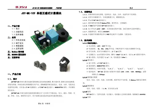
JSY-MK-109 单相互感式计量模块一、 产品介绍1.1 简介 1.2 功能特点 1.3 技术参数 二、 应用2.1 外形及安装 2.2 端子定义 2.3 典型接线 2.4 应用说明 三、 Modbus 寄存器 四、 MODBUS 通讯规约 五、 注意事项一、产品介绍1.1、 简介JSY-MK-109单相互感式电能质量检测仪是高度集成测量、数字通讯等,能够完成电能测量、采集及传输,单相交流电参数测量应用产品,准确测量单相交流电压、电流、功率、电量及总电量等电参数,并具备1路9V 电源输出,1路RS-485通讯接口,MODBUS-RTU 规约,具有极优的性价比。
JSY-MK-109 单相互感式电能质量检测仪可广泛应用于节能改造、电力、通信、铁路、交通、环保、石化、钢铁等行业中,用于监测交流设备的电流和电量消耗情况。
1.2、 功能特点1.2.1. 采集单相交流电参数,包括电压、电流、功率、电能等多个电参量; 1.2.2. 采用专用测量芯片,有效值测量方式,测量精度高; 1.2.3. 带1路RS-485通讯接口;1.2.4. 通信规约采用标准Modbus-RTU ,兼容性好,方便编程; 1.2.5. 带ESD 保护电路的RS-485通信接口;1.2.6. 宽工作电压AC80~265V ,并具防接反保护功能,接反电源不会损坏模块;; 1.2.7. 高隔离电压,耐压达DC2000V ;1.2.8. 可选配不同规格单匝穿心PCB 固定或开口互感器,方便易用;1.3、 技术参数1.3.1 单相交流输入1) 电压量程:100V 、220V 等可选;2) 电流量程: 5A 、50A 、100A 等可选;外配外接开口电流互感器型号可选; 3) 信号处理:采用专用测量芯片,24位AD 采样;4) 过载能力:1.2倍量程可持续;瞬间(<20mS)电流5倍,电压1.5倍量程不损坏; 5) 输入阻抗:电压通道>1 k Ω/V ;电流通道≤100m Ω; 1.3.2 通讯接口1) 接口类型:1路RS-485接口; 2) 通讯规约:MODBUS-RTU 规约;3) 数据格式:可软件设置,“n,8,1”、 “e,8,1”、 “o,8,1”、 “n,8,2”; 4) 通讯速率: RS-485通讯接口波特率可设置1200、2400、4800、9600Bps ;波特率默认为4800bps ;1.3.3 测量输出数据电压、电流、功率、电能、功率因数、频率等多个电参量,见Mdobus 数据寄存器列表;1.3.4 测量精度电压、电流、电量:±1.0%;有功电度1级 1.3.5 隔离RS-485接口,与供电电源、电压输入、电流输入之间相互隔离;隔离耐压2000VDC ; 1.3.6 电源1)可选100V、220V、电压线路100V~220V2)AC220V供电时,峰值电压不得超过265V;典型功耗:≤2W;1.3.7工作环境1)工作温度:-20~+70℃;存放温度:-40~+85℃;2)相对湿度:5~95%,无结露(在40℃下);3)海拔高度:0~3000米;4)环境:无爆炸、腐蚀气体及导电尘埃,无显著摇动、振动和冲击的场所;1.3.8温度漂移:≤100ppm/℃;1.3.9安装方式:螺丝固定安装孔距为65*45MM1.3.10模块尺寸: 72×51×24mm二、应用2.1、外形及安装图 2.1 外形尺寸图(单位:mm)电流互感器外形图电流互感器外型及尺寸图:50A穿心式电流互感器外形尺寸图100A开口式电流互感器外形尺寸图2.2、接口定义图2.2.1 VL(火线)、VN(零线)为被测电压接线口,模块左侧和下侧VL、VN两者效果一致,可根据需要进行选择;2.2.2 被测电流线从电流互感器或外接互感器中穿过,无具体方向要求;如上图所示;2.2.3 RS-485通讯接口为2P接线插座,从上往下为485B、485A,TXD为模块数据发送,RXD为模块数据接收、GND为公共地,VA、G1辅助电源正负极,可对外提供DC9V电源、电流不大于50MA。
S H A N D O N G L E T R U E T E C H N O L O G Y C O.,L T DISO9001国际质量体系认证企业国家高新技术企业LCDG-DTSD6000组合电表说明书山东力创科技股份有限公司序言感谢您选用山东力创科技股份有限公司的LCDG-DTSD6000组合电表产品。
我们建议在安装、操作或维护此设备之前,请仔细阅读本手册,并逐步熟悉这种仪表。
以下特殊信息可能贯穿出现在本手册中或在设备上,用来警示潜在的危险或用于阐释和规定操作规程,请注意。
©2017Shandong Lichuang Science&Technology Co.,Ltd版权所有本出版物中所包含的信息仅为所显示的目的而制作。
没有本公司的书面同意,本手册及随同组合电表设备一起提供的其他文件不得被复制,不管是部分或全部。
用于描述设备的图纸及图片仅作为一般参考作用,而不能确保每个细节的完整性与准确性.。
本手册对应的相关内容如有更改,恕不另行通知。
订货前,请垂询本公司或当地经销商以获悉本产品的最新规格。
安全警告按照说明书指示的使用方法正确使用可以避免产品出现不必要的故障或损坏,并可保证使用者的安全。
1、使用过程中对操作者造成危险的安全注意事项。
(1)为确保正确、安全使用本产品,需专业电工安装或拆卸;(2)安装或拆卸操作时,必须断开主电源;2、个人维护、调整或更换易损件时,可能对操作者造成人身伤害。
(1)请勿擅自拆开产品,更不可带电拆机。
请用户严格按照本说明书说明安装和使用本产品,以获得最佳使用效果。
安全须知在试图安装、操作或维护此设备之前,请仔细阅读本手册,拿到它并逐步熟悉这种仪表。
以下特殊信息可能贯穿出现在本手册中或在设备上,用来警示潜在的危险或对于阐释和规定操作规程的信息提请注意。
附有这种安全标志示意周围存在着电力危险,假若未遵照一定的指令将会导致人身伤害。
这是安全警告标志,用来警告你潜在人身伤害的危险,遵照此标志后的所有安全信息,避免可能的伤害或死亡。
LCD 模块使用手册1.使用范围----------------------------------------------------22.质量保证----------------------------------------------------23.性能特点----------------------------------------------------24.外形图-------------------------------------------------------55.I/O接口特性-----------------------------------------------76.质量等级---------------------------------------------------107.可靠性---------------------------------------------------128.生产注意事项---------------------------------------------139.使用注意事项---------------------------------------------141.使用范围该检验标准适用于大连佳显电子有限公司设计提供的标准液晶显示模块。
如果在使用中出现了异常问题或没有列明的项目,建议同最近的供应商或本公司联系。
2.质量保证如在此手册列明的正常条件下使用、储存该产品,公司将提供12个月的质量保证。
3.性能特点3-1.性能:显示方式 : 半透、正显灰白色TN LCD显示颜色 : 显示点: 黑色背景: 灰白色显示形式: 3×6位笔段式显示(带小数点)输入数据 : 来自MPU的1位串行数据接口驱动方式 : 静态视角: 6 点背光 : LED3-2.机械性能:项目规格单位外形尺寸 170.0(W)×178.8(H) ×15.0 Max.(T) mm显示位数3×6位(带小数点) —视域3×130.6(W)×31.5(H) mm显示图形域3×127.6(W)×25.4(H) mm字符间距 22.0 mm 字符尺寸 12.7(W)×25.4(H) mm 重量 Approx.380 g3-3.极限参数:项 目 符 号 最小值最大值 单位 注 释逻辑 Vdd 0 6.0 V电源电压LCD 驱动 V LCD0 6.0 V 输入电压 Vi 0 Vdd V 操作温度 Top -30 70 ℃ 储存温度 Tstg -40 80 ℃ 湿度 — — 90 %RH3-4. 电气特性: 3-4-1. 电气参数项 目 符 号 条 件 最小值典型值 最大值 单 位逻辑 Vdd 4. 5 5.0 5. 5电源电压LCD 驱动 V LCD4. 5 —5. 5 高电平 Vih Vdd=5V ±10% 0.8Vdd — Vdd输入电压 低电平 Vil 0 — 0.2 Vdd 高电平 V oh Vdd=5V ±10% Vdd-0.3— —输出电压低电平 V ol — — 0.3V频 率 Fflm Vdd=5V 31 33 35 Hz 逻辑 Idd— 0.5 1.0功 耗LCD 驱动 I LCDVdd=5V Fflm=33Hz — 0.22 0.25 mATa= -30℃ φ=0°,θ=0° — 5.5 5.8 Ta= 25℃ φ=0°,θ=0° — 5.0 — LCD 驱动电压(推荐电压)V LCDTa= 70℃ φ=0°,θ=0°4.2 4.5 —V3-4-2. LED 背光规格 标 准 值项目单位最小值典型值 最大值条 件电源电压 V 10.5 11 12 If=40mA 亮 度 cd/m 2 — 17 — If=40mA(单片玻璃) 电 流 mA — — 380 单片玻璃 寿 命 Hrs 5000 — 发光颜色 — 黄绿色 — 操作温度 ℃ -30 ~ 70 — 储存温度 ℃ -40 ~ 80 —3-5. 电光特性项 目 符号温度 条件 最小值典型值最大值 单位 注释 -30℃ — 5.5 5.825℃ — 5.0 —LCD 驱动电压(推荐电压)V op 70℃ φ=0°,θ=0° 4.2 4.5 — V 1,2,5 0℃ — 1500 2000 上升时间 tr 25℃ — 150 2000℃ — 3000 3500响应 时间 衰退时间 td 25℃ φ=0°,θ=0°— 200 250mS 1,3,5垂直 -35 — 35视 角 Δφ 25℃ 水平 -30 — 30deg. 1,4,5对比度 K 25℃ φ=0°,θ=0° 2.0 5.0 — — 1,5,6注意:<1> φ和θ的定义<2> 在此电压范围内能获得对比度大于2(k ≥2)注意:<3> 响应时间波形定义(ΔΦ) ΔΦ=|Φ1-Φ2|非选择点的亮度(B2)4.外形图(见下页)PIN# 1 2 3 4 5 6 7 SYM LED -LED +Vss Vdd CLK DIN CL15.I/O接口特性5-1. I/O 接口表:管脚号符号功能- 背光电源(地)1 LED2 LED+ 背光电源(+12V)3 Vss 电源(地)4 Vdd 电源 (+5V)5 CLK 时钟信号输入6 DIN 串行数据输入7 CL1 串行数据锁存信号5-2. 时序及时序图:项目 符号 条件最小值最大值 单位 时钟频率 Fcl — 400 kHz 时钟上升/下降时间 Tct— 200 高电平 Tcwh800—时钟宽度低电平 Tcwl 800 — 数据建立时间 Tsu 300 —数据保持时间 TdhVdd=5V ±10%Ta=25℃ 300 —ns时序图5-3. 显示数据格式及顺序:左Æ右 位1 位2位3位4位5 位6行 1 18 17 16 15 14 13 行 2 12 11 10 9 8 7 行 3 6 5 4 3 2 1注释:每次刷新屏幕需重新送入18个数。
GCS 系列(中文液晶显示)数显表说明书两轴数显表、叁轴数显表、火花机专用数显表深圳市恒兴星精密仪器有限公司SHENZHEN HENGXINGXING PRECISION INTRUMENTS CO.LTD.目录目录 (1)结构原理 (1)第一章基本操作说明 (2)一、开机 (2)二、清零 (2)三、公./英制转换 (2)四、自动分中 (3)五、绝对/相对/1000组用户坐标系 (3)第二章1000 组辅助零位功能 (5)第三章专用功能 (6)一、圆周分孔 (6)二、斜线分孔 (8)三、圆弧分孔 (10)四、斜面(斜度)加工 (14)第四章放电加工功能 (16)一、设置放电加工参数 (17)二、EDM加工 (18)三、圆周分孔、斜线分孔与EDM功能结合使用 (25)第五章计算器功能 (26)一、进入和退出计算器功能 (26)二、计算器结果转移 (26)第六章内部参数设定 (27)一、进入内部参数设定,退出内部参数设定 (27)二、设置光栅尺计数方向 (28)三、设置线性误差修正值 (28)四、设置光栅尺解析度 (29)五、设置继电器动作模式 (30)六、10设置SDM置数模式 (30)七、系统总清 (31)结构原理本公司生产的GCS系列的数显表,是一种为机床、磨床、铣床、镗床和火花机提供的位置检测的精密测量仪表。
其工作原理如下:光栅尺数显表GCS系列数显表规格输入电压范围85V-250V最大功耗15W工作温度0℃-40℃储存温度-20℃-40℃相对温度<90%重量约1.45kg尺寸295×185×45(单位:mm)坐标数2(GCSM-2), 3(GCSM-3,GSSE)操作键盘密封薄膜式轻触键盘光栅尺接口9PD/7PD/15PD光栅尺信号两路相差90°相位角的TTL方波,驱动能力>10mA 光栅尺解析度0.05μm,0.1μm,0.2μm,0.5μm,1μm,2μm,5μm,10μm,20μm,50μm,10种GCSEDM接口输出一路开关信号,驱动电源>100mA选购RS232接口一路TX,RX信号外部寻边接口5V高电平,驱动电流>10mA第一章基本操作说明一、开机功能介绍:开电源开关,数显表进入正常显示状态。

单相直流多功能电力仪表(LCD版)使用手册(2012.08.V1.0)目录一、概述 (1)二、技术参数 (1)2.1 辅助电源 (2)2.2 输入信号 (2)三、仪表外型、开孔尺寸及面板说明 (2)3.1按键定义 (2)3.2 测量显示 (2)3.3 页面显示示意图 (3)3.4、编程操作 (4)3.5菜单的组织结构 (4)3.6 编程菜单结构图 (5)四、数字通讯 (5)4.1 报文格式指令 (8)MODBUS-RTU通讯地址信息表 (9)五、接线示意图(以实物接线图为准) (10)多功能电力仪表一、概述多功能电力仪表是一种具有可编程测量、显示、数字通讯和电能脉冲变送输出等功能的多功能电力仪表,能够完成电量测量、电能计量、数据显示、采集及传输,可广泛应用变电站自动化,配电自动化、智能建筑、企业内部的电能测量、管理、考核。
测量精度为0.5级、实现LED 现场显示和远程RS-485数字通讯接口,采用MODBUS-RTU通讯协议。
二、技术参数单相多功能电力仪表具备通用的(AC/DC)电源输入接口,若不作特殊声明,提供的是AC/DC85~270V电源接口的标准产品,请保证所提供的电源适用于该系列的产品,以防止损坏产品。
注:采用交流供电时,建议在火线一侧安装1A保险丝。
电力品质较差时,建议在电源回路安装浪涌抑制器防止雷击,以及快速脉冲群抑制器。
2.2 输入信号:单相多功能电力仪表采用了每个测量通道单独采集的计算方式,保证了使用时完全一致对称。
2.2.1 电压输入:输入电压应不高于产品的额定输入电压(500V),在电压输入端须安装1A保险丝。
2.2.2 电流输入:标准额定输入电流为1A,大于1A的情况应使用分流器。
如果使用的分流器上连有其它仪表,接线应采用串接方式。
2.2.3 要确保输入电压、电流相对应,顺序一致,方向一致;否则会出现数值和符号错误!(功率和电能)三、仪表外型、开孔尺寸及面板说明3.1按键定义菜单键:用于选择菜单界面、退出功能和返回上级菜单功能。
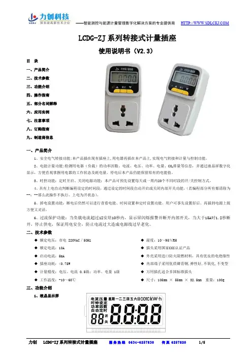
LCDG-ZJ 系列转接式计量插座使用说明书(V2.3)目 录 一、产品简介 二、技术参数 三、功能介绍 四、操作指南 五、部分名词解释 六、应用实例 七、注意事项 八、订购指南 九、制造商信息一、产品简介1、安全电气转接功能:本产品插在现有插座上,用电器再插在本产品上,实现电气转接和计量与控制功能。
2、电能计量功能:检测用电器(负载)的功率因数、电流、电压、功率、电量、CO 2排量等信息,并通过液晶屏数字化显示,方便直观掌握用电器的工作状态及耗电量。
停电后本产品仍能保留原有的电能值。
3、时控功能:定时开启、关闭电源功能;本产品可预先设置每天或一周内20个不同时段的开/关控制方式。
4、具有上电自动判断编程设定的时间段,通过设定的时间段自动开启或关闭内部开关功能。
(若编程部分所有都清除为--:--那么此操作不执行,上电为开状态)。
5、掉电设置功能:断电后仍然可以进行查看电能、时间设置和定时设置功能。
用户可事先设置好后、再插到电源上既方便又灵活。
6、过流保护功能:当负载电流超过12安培10秒内,显示屏闪烁报警并断开内部开关,当大于15A 时1.2秒断开,停止供电,保证用电安全,防止电流过大造成电源线过早老化。
二、技术参数◆ 额定电压:市电 220VAC /50Hz ◆ 额定电流:10A ◆ 启动电流:5mA ◆ 插座功耗:<0.75W◆ 计量精度:电压、电流 0.5级;功率、电量 1级 ◆ 工作温度:-10~60℃◆ 湿度:10~95%RH ◆ 插头采用国家CCC 认证产品◆ 外壳采用进口防火阻燃材料,具有优良的电绝缘性 ◆ 内部端子采用优质磷青铜,弹性好,不氧化,不变型 ◆ 万用插孔适合多国标准插头◆ 尺寸:105mm × 55mm × 32.5mm 重量:100g三、功能介绍1、液晶显示屏2、按键共三个按键:[▲]键、[模式]键和[▼]键(LCDG-ZJ110-012产品中[模式]键不可用)。

版本号V6.0Yk三相/单相电力仪表产品使用说明书(适用于单/三相电压表、电流表、单相功率表、功率因数表、频率表、单相组合表)上海亚度电子科技有限公司目录1、概述 (1)2、技术参数 (1)3、安装与接线 (2)3.1仪表尺寸 (2)3.2安装方法 (2)3.3接线端子功能说明 (3)3.4接线注意事项 (7)4、编程操作说明 (7)4.1面板显示信息说明 (7)4.2编程操作 (9)4.3典型操作范例 (12)5、功能模块 (16)5.1开关量输入/输出‥ (16)5.2模拟量变送输出 (18)6、数字通讯 (20)6.1硬件连接 (20)6.2通讯协议 (21)6.3寄存器地址信息表 (24)7、常见问题及解决办法‥ (25)1、概 述单/三相数显仪表是一种具有可编程测量、显示、数字通讯功能的电测仪表,采用交流采样技术,可直接或间接测量单/三相电网中的电流或电压,可广泛应用变电站自动化,配电自动化、智能建筑、企业内部的电量测量、管理、考核。
2、技术参数项目参数额定值 AC400V过负荷持续:1.2倍 瞬时:2倍 功耗<1V A(每相) 阻抗 >500k电压 精度 RMS 测量,精度等级0.5级 (可定做0.2级) 额定值 AC5A过负荷持续:1.2倍 瞬时:2倍 功耗<0.4V A(每相) 阻抗 >2m Ω电流 精度 RMS 测量,精度等级0.5级 (可定做0.2级) 频率范围 45-65Hz输 入 测 量 显 示显示 可编程、切换、四位LED 或LCD 显示工作范围 标配AC220V±10%,可选配DC24V 48V AC380V AC/DC 80-265V;电源功耗 ≤5V A数字接口 RS-485接口、MODUS-RTU 协议(选配) 开关量输入 2路或4路开关量输入、干接点方式(选配)开关量输出 2路或3路,继电器触点输出,AC3A/250V DC3A/30V(选配)输出模拟量输出 1路或3路模拟量输出、4-20mA/0-20mA (选配) 工作环境 -10-55℃ 环境 储存环境 -20-75℃耐压 输入/电源>2kV ,输入/输出>2kV ,电源输出>1kV 安全绝缘输入、输出、电源对外壳>50M Ω3、安装与接线3.1仪表尺寸外形尺寸mm (LxH) 壳体尺寸mm(AxB)开孔尺寸mm(SxY)总长mm(N)深度mm(M)120x120 110x110 111x111 95 84 96x96 90x90 91x91 95 84 80x80 75x75 76x76 95 84 72x72 66x66 67x67 95 84 48x48 44x44 45x45 95 843.2安装方法:3.3接线端子功能说明3.3.1端子功能编号单/三相仪表端子功能编号表:端子号端子功能端子功能说明端子号 端子功能端子功能说明1L辅助电源相线端24 DI1第一路开入接入端2N辅助电源零线端25 DI2第二路开入接入端26 DI3第三路开入接入端3IA*/I*A相电流进线端/单相电流进线端 27 DI4第四路开入接入端28 DGND 开入公共端,负端4IA/I A相电流出线端/单相电流出线端295IB*B相电流进线端30DO1 第一路开出端6IB B相电流出线端317IC*C相电流进线端32DO2 第二路开出端8IC C相电流出线端3334 DO3 第三路开出端9UA/UL A相电压接入端/单相电压相线端37 AO1 第一路模拟量输出端11UB B相电压接入端39 AO2 第二路模拟量输出端13UC C相电压接入端41 AO3 第三路模拟量输出端15UN零线接入端45 AGND 模拟量输出公共负端21A485通讯A+端22B485通讯B-端3.3.2信号输入接线方式3.3.3接线端子背视图(供参考,以实物为准)注:以上为所有附加功能俱全时的接线图,如果用户使用过程中发现某些功能少了,表示所选的产品不支持该功能。
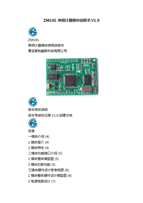
ZM101-单相计量模块说明书V1.0ZM101单相计量模块使用说明书青岛智物酷联科技有限公司版本修改说明版本号修改记录V1.0创建文档目录一模块介绍 (4)1 模块简介 (4)2 模块特性 (4)二模块功能接口介绍 (5)1 模块整体模型图 (5)2 模块引脚功能 (5)三模块硬件设计参考电路 (6)1 模块整体硬件设计模型图 (6)2 电源电路设计 (7)3 485通信电路设计 (7)四模块软件应用 (8)1 DL/T645-2007协议简述 (8)五总结 (13)一模块介绍1 模块简介ZM101系列多功能高精单相专用计量模块,模块集成模块sigma-delta ADC,参考电压电路以及所有功率,能量,有效电压,电流,功率因数以及频率测量的数字信号处理等电路,能够准确测量有功功率,有功电量,无功电量,视在电量,同时还能测量电压,电流,功率,功率因数等各种电参数。
满足用户对电力检测的各项要求。
集成MCU和计量专用芯片,用户应用简单方便,只需通过UART就可以和模块进行通信,获得电相关参数信息,方便开发设计,简化设计难度,为产品尽快上市提供帮助。
2 模块特性高精度,在输入动态工作范围5000:1内,分线性测量误差小于1% 有功测量满足0.5级,支持IEC62053-22:2003,GB/T17215.322-2008 提供基波有功功率,电能,电压,电流有效值输出提供有功功率及其电能计算提供功率因数,相位角信息输出提供电压,电流有效值计算,在500:1动态范围,有效值精度优于0.1% 提供有功反向指示提供UART通信接口,TTL工作电平,通信波特率2400-9600可调内置通信协议,支持645协议二模块功能接口介绍1 模块整体模型图2 模块引脚功能特性功能描述引脚编号引脚名称1 VCC 输入模块电源引脚。
工作电压:5V. 推荐:.该引脚可接10UF/10V电容并联100NF/10V瓷介电容进行去耦2 VBATT 输入时钟电压引脚.工作推荐电压:3V3 GND 参考地数字电源地4 P0 输入/用户可编程IO口.推荐:不使用时悬空输出5 P1 输入/用户可编程IO口.推荐:不使用时悬空输出6 P2 输入/用户可编程IO口.推荐:不使用时悬空输出7 RD 输出用户采用485通信时配合UART使用,485通信发送接收选择端口。

GW Instek GPM-8310 is a digital power meter for single-phase (1P/2W) AC power measurement. Features include DC, 0.1Hz~100kHz test bandwidth, 16bits A/D, and 300 kHz sampling rate. It adopts 5” TFT LCD screen with a five-digit measurement display and provides 25 power measurement related parameters, and has a high-precision measurement capability. It also features the ability to display waveform (voltage/current/power), the integration measurement function, harmonic measurement and analysis of each order (meeting the IEC 61000-4-7 harmonics measurement requirements at 50/60Hz), external sensor input terminals, and various communication interfaces, etc., to help users achieve clear, convenient and accurate power measurements. This power meter is a most cost-effective power meter with most complete functionalities among the products of the same category.The rated direct input voltage of GPM-8310 is 600V and the input current is 20A. The minimum current level is 5mA (resolution up to0.1uA) and the power measurement resolution is 0.1uW. The crest factor can reach 3 (half measurement range can reach 6 or 6A), and the voltage/current/power measurement capability can reach (±0.05% reading ±0.1% level). Different measurement modes can be selected according to ( AC+DC/ AC/ DC/ V-MEAN), providing up to 25 relevant parameters for power measurement, including voltage (Vrms/ Vac/ Vdc/ Vmn/ V+pk / V-pk), current (Irms/ Iac/ Idc/ I+pk/ I-pk), frequency (VHz/ IHz), power (P/ P+pk/ P-pk), crest factor (CFV/ CFI), apparent power (VA), reactive power (VAR), power factor (PF), phase angle (DEG), total harmonic distortion rate (THDV/THDI), maximum current ratio (MCR), and the MATH calculation function. Hence, for the measurement of low current/low power such as standby power consumption, or the measurement of power consumption of general products, this power meter provides the best range and accuracy support.GPM-8310 also makes good use of the advantages of the TFT LCD to display the results of parameter measurement by using numerical and graphical methods. In terms of numerical values, the general mode and the simple mode are provided. The general mode can display 10 measurement parameters (2 main measurements + 8 monitoring measurements), and the simple mode can display four measurement parameters. These displayed parameters can be arbitrarily selected from 25 power parameters according to the needs of users. In terms of graphic display, a simple oscilloscope mode is provided to display waveforms for three parameters including voltage, current and power. In addition, the measurement and analysis of each harmonic order of the measurement signal can be completely displayed by numerical values or bar graphs. This power meter not only meets the needs of accuracy and legibility in process testing, but also meets the needs of diverse measurement applications in R&D design and quality verification.In addition, the performance of GPM-8310 in auxiliary measurement mechanism/function is also comprehensive. For the application of measuring large voltage, the VT rate setting can be used with an external voltage Potential Transformer. For the measurement of large current, the type of current transformer ~ voltage output type or current output type will determine the applied method. If it is a current output type, it can be directly locked to the rear panel of the instrument and collocated with the CT rate setting to conduct measurement. If it is a voltage output type, measurement can be conducted through the external current sensor input terminals (EXT1/EXT2) provided by GPM-8310. Automatic level-changing can self-define the required level to save level-changing time. 10,000 lots of internal memories can be used to store measurement data according to the update rate set by GPM-8310 or a user-defined time interval for subsequent analysis. In terms of data retrieval and storage, GPM-8310 provides a variety of communication interfaces including RS-232C/ USB device (virtual COM)/ LAN/ GPIB. Users can write programs to read the measurement results according to their habits or with existing system interfaces and there is no need to procure interfaces. USB host supports GPM-8310 screen capture, internal record data access, and firmware update. For the needs of external signal control or the use of data recorder to record data, GPM-8310 also provides an optional Digital I/O (DA4) interface (must be installed before leaving the factory), which can be connected to an external controller such as PLC or a data recorder to meet the application of automatic measurement or long recording.Numerical (General)Mode Numerical (Simple)ModeWaveformModeHarmonic (Bar Graph)MeasurementHarmonic (Table Column)MeasurementGPM-8310 provides the numerical value display mode and the waveform display mode, which help users to maximize the benefit of their measurement. Under the numerical mode, there are the general mode and the simple mode. The general mode has related measurement settings and can simultaneously display 10 measurement parameters (2 main measurements and 8 secondary measurements). The simple mode displays only 4 measurement parameter results. The parameters in each mode can be arranged and combined as required. Under the graphic mode, a simple oscilloscope function is provided to display the waveforms of three parameters including voltage, current and power. The horizontal scale can be adjusted (from 25us/div ~ 1s/div according to the set data update rate), and 3 magnification rates for waveform observation are also provided for users to select. In the harmonic measurement, the measurement results of each order of harmonics can be displayed by bar graphs, and a specific observation order can be specified. The relevant values of each order of harmonics (voltage/current/power/voltage distortion ratio/current distortion ratio/power distortion ratio/voltage phase angle/current phase angle) can be completely recorded anddisplayed.External Current Sensor Input FLEXIBLE LEVEL-CHANGING MECHANISMSUPERB MEASUREMENT ASSISTANCERatio Configuration GPM-8310 provides a variety of measurement items and functions,including voltage, current, frequency, effective power, apparent power,reactive power, power factor, crest factor, total harmonic distortion, andcan also measure the maximum current ratio. GPM-8310 is also equippedwith the measurement function of power or current time integration forthe DUT. Users set a period of time to perform instantaneous power With respect to the support of measurement assistance, the performanceof GPM-8310 is outstanding. First of all, for the measurement of highvoltage/high power, the setting of voltage ratio/power ratio is provided torestore the attenuated ratio to a true value. For the measurement of largecurrent, other than the setting of current ratio, external current sensorterminals (EXT1/EXT2) can be utilized to connect with a voltage outputtype current transformer, making large current measurement more GPM-8310 provides the measurement of the integration function underthe automatic level-changing mode to allow users to fully calculate thetotal value of the power consumption of the DUT from the beginning tothe end of the integration function. In addition, GPM-8310 also supports integration at the set time period, and then divide by the time to obtain the average power of the DUT. In addition, when performing integration measurement, GPM-8310 supports automatic level-changing function for the power change of the DUT at different times in order to obtain the most complete integration result within the set time.convenient. In addition, GPM-8310 provides 4 sets of panel settings for storage/recall and memory for storing 10,000 lots of measurement values. The measurement storage can log the measurement results based upon the update rate or a self-defined time interval to facilitate the subsequent analysis. The USB host on the front panel supports screen capture, measurement value storage, and GPM-8310 firmware update.self-defined setting mechanism for level-changing. Users can select the required level to be changed to save time on level-changing and expeditethe test.Note : “*” Only applicable to specific measurement modes for selectionSelf-defined automatic level-changing mechanism Automatic level-changing under the integration functionGPM-001 Test FixtureGPM-001(EU) Test FixtureGTL-210 Test Lead GTL-213 Test Lead 9876543USBUSB HostDevice LAN 2145689723GPM-8310 provides comprehensive and diverse communicationsinterfaces including RS-232 / USB / LAN / GPIB, which are suitable forcustomers to write computer software for remote control and thecollection of measurement results through commands. The optionalDigital I/O (DA4) interface provides 3 different modes: the external controlmode, the DA4 output mode and the self-defined output mode based onuser settings. When the setting is in the external control mode, it allowsusers to activate, stop, trigger or reset the integration measurement function through external signals. When the setting is in the DA4 output mode, users can define 4 measurement parameter values from the 25 measurement parameters provided (even with the result of integration measurement) to produce outputs by a fixed level (full scale +5V) or a manual level (full scale ±5V) and receive results by collocating with a data recorder. When the setting is in the self-defined output mode, a communications interface is required to control the action of each defined pin through commands.Practical InterfaceDA4 Interface Mechanism DA4。
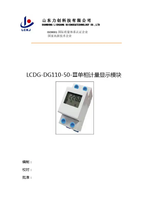
山东力创科技有限公司SHANDONG LICHUANG SCIENCE&TECHNOLOGY CO.,LTDISO9001国际质量体系认证企业国家高新技术企业LCDG-DG110-50-Ⅲ单相计量显示模块使用说明书编制:校对:批准:山东力创科技有限公司2013年10 月29日编制及修改记录修订日期版本编制修改原因2013-11-23 V2.0 版本升级版权所有,未经本公司书面许可,此手册中任何段落,章节内容均不得被摘抄、拷贝或以任何形式复制、传播,否则一切后果由违者自负。
本公司保留一切法律权利。
本公司保留对本手册所描述之产品规格进行修改的权利,恕不另行通知,订货前,请向厂商或代理商获取本产品的最新规格。
安全警告按照说明书指示的使用方法正确使用可以避免产品出现不必要的故障或损坏,并可保证使用者的安全。
1、使用过程中对操作者造成危险的安全注意事项。
(1)为确保正确、安全使用本产品,需专业电工安装或拆卸;(2)安装或拆卸操作时,必须断开主电源;2、个人维护、调整或更换易损件时,可能对操作者造成人身伤害。
(1)请勿擅自拆开产品,更不可带电拆机。
请用户严格按照本说明书说明安装和使用本产品,以获得最佳使用效果。
1、概述2、产品的规格型号3、主要技术参数4、安装与接线4.1、外形尺寸4.2、接线图或安装图5、显示说明6、包装7、注意事项1、概述■ 测量并显示单相电压、电流、有功功率、有功电量。
■ 掉电保存电能累计值。
■ 电压信号供电,不需要辅助电源。
■ 外形美观小巧,重量轻,性能优良可靠。
■ 5位宽温型LCD 显示,轮显。
■ 35mm 标准导轨安装方式。
2、产品的规格型号3、主要技术参数■ 额定电压:市电 220VAC ■ 额定电流:50A ■ 输入频率:50Hz ■ 计量精度:1级■ 工作温度:-10~60℃;储存湿度:≤85% RH4、安装与接线4.1、外形尺寸(单位:mm )本产品安装在TH35-7.5标准导轨上,采用嵌入式安装。
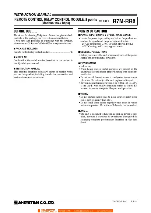
BEFORE USE ....Thank you for choosing M-System. Before use, please check contents of the package you received as outlined below.If you have any problems or questions with the product, please contact M-System’s Sales Office or representatives.■PACKAGE INCLUDES:Remote control relay control module (1)■MODEL NO.Confirm that the model number described on the product is exactly what you ordered.■INSTRUCTION MANUALThis manual describes necessary points of caution when you use this product, including installation, connection and basic maintenance procedures.POINTS OF CAUTION■POWER INPUT RATING & OPERATIONAL RANGE• Locate the power input rating marked on the product and confirm its operational range as indicated below:24V AC rating: 24V ±10%, 50/60Hz, approx. 140mA24V DC rating: 24V ±10%, approx. 60mA■GENERAL PRECAUTIONS• Before you remove the unit or mount it, turn off the power supply and output signal for safety.■ENVIRONMENT• Indoor use.• When heavy dust or metal particles are present in the air, install the unit inside proper housing with sufficient ventilation.• Do not install the unit where it is subjected to continuous vibration. Do not subject the unit to physical impact.• Environmental temperature must be within -10 to +55°C (14 to 131°F) with relative humidity within 30 to 90% RH in order to ensure adequate life span and operation.■WIRING• Do not install cables close to noise sources (relay drive cable, high frequency line, etc.).• Do not bind these cables together with those in which noises are present. Do not install them in the same duct.■AND ....• The unit is designed to function as soon as power is sup-plied, however, a warm up for 10 minutes is required for satisfying complete performance described in the data sheet.■I / O STATUS INDICATOR LEDOutput and feedback input status are indicated with LED.ON: LED on OFF: LED off ■POWER SUPPLY, MODBUS TERMINAL ASSIGNMENT■4DA 567123DG U(+)V(–)DB SLD FG (1) DB –(2) SLD Shield (3) FG FG (4) DA –(5) DG –(6) U(+) Power input (7)V(–)Power inputOUTPUT TERMINAL ASSIGNMENT10NC 11Y012Y11NC 2C03C113Y24C214Y35C315Y46C416Y57C517Y68C69C718Y7NO.ID FUNCTION NO.ID FUNCTION 1NC No connection 10NC No connection 2C0Common 11Y0Output 03C1Common 12Y1Output 14C2Common 13Y2Output 25C3Common 14Y3Output 36C4Common 15Y4Output 47C5Common 16Y5Output 58C6Common 17Y6Output 69C7Common18Y7Output 7■TERMINATING RESISTORTo use the terminating resistor, turn the switch ON, and OFF to invalidate.(Factory setting OFF)■EXTENSION MODULECombinations with all extension modules are available.■STATUS INDICATOR LED ID COLOR FUNCTIONPWR Red Turns on when the internal 5V is suppliednormally.RUN Red Turns on when the refresh data is received normally.ERR Red Turns on when the received data is abnormal.SD Red Turns on when the module is transmitting.RDRedTurns on when the module is receiving.■NODE ADDRESSNode Address is selected between 1 and 99 in decimal. The left switch determines the tenths place digit, while the right switch does the ones place digit of the address.■Node Address Setting (x1)Node Address Setting (x10)BAUD RATEBaud Rate is selected with the rotary switch.■Baud Rate Setting5: 1200 bps 6: 14.4 kbps 7: 28.8 kbps 8: 57.6 kbps 9: 115.2 kbps OPERATING MODE •Extension (SW1-1, 1-2)SW1-1SW1-2EXTENSION OFF OFF No extension (*)ON OFF Discrete input 8 or 16 points OFFONDiscrete output 8 or 16 points(*) Factory settingNote : Be sure to set unused SW1-3 through 1-8 to OFF .■PC CONFIGURATORThe following parameters can be set with using PC Configu-rator Software.• Modbus parameters: Parity , bit length, stop bitCOMPONENT IDENTIFICATION■ SIDE VIEW■ FRONT VIEW(A) Status Indicator LED(B) Node Address Setting Rotary SW (C) Baud Rate Setting Rotary SW(D) Operating Mode Setting DIP SW (SW1)(E) PC Configurator Jack (F) I/O Status Indicator LED(G) Modbus, Power Supply Terminals (H) Output Terminals( I ) Terminating Resistor SWI/O DATA DESCRIPTION■OUTPUTBIT CHANNEL DAT A ST ATE0Y00OFF Output 1ON Output1Y10OFF Output 1ON Output2Y20OFF Output 1ON Output3Y30OFF Output 1ON Output4Y40OFF Output 1ON Output5Y50OFF Output 1ON Output6Y60OFF Output 1ON Output7Y70OFF Output 1ON Output8——Invalid 9——Invalid 10——Invalid 11——Invalid 12——Invalid 13——Invalid 14——Invalid 15——Invalid ■FEEDBACK INPUTBIT CHANNEL DA TA STA TE0Y00OFF Output1ON Output 1Y10OFF Output1ON Output 2Y20OFF Output1ON Output 3Y30OFF Output1ON Output 4Y40OFF Output1ON Output 5Y50OFF Output1ON Output 6Y60OFF Output1ON Output 7Y70OFF Output1ON Output 8——Invalid9——Invalid10——Invalid11——Invalid12——Invalid13——Invalid14——Invalid15——InvalidEXTERNAL DIMENSIONS unit: mm (inch)TERMINALS for Modbus, POWER TERMINALS for OUTPUTWIRING INSTRUCTIONS■SCREW TERMINAL Torque : 0.5 N·m■SOLDERLESS TERMINAL mm (inch)Refer to the drawing below for recommended ring tongue terminal size. Spade tongue type is also applicable. Applicable wire size 0.25 to 1.65 mm 2 (AWG22 - 16)Recommended manufacturer: J apan Solderless Terminal MFG.Co.Ltd, Nichifu Co.,ltdCONNECTION DIAGRAMConnect the unit as in the diagram below .Y0Y1C1Y2C2Y3C3Y4C4Y5C5Y6C6Y7C7C0DA DB DG SLD FG U V −■Output Connection ExampleCaution: FG terminal is NOT a protective conductor terminal.MASTER CONNECTION ■ MASTER CONNECTIONHost PCRemote Unit Remote UnitBe sure to connect the terminating resistor included in the product package to the unit at both ends of transmission line.The terminator must be connected across DA and DB.The Host PC can be located other than at the extreme ends of transmission line.。
LCDG系列计量插排使用说明书型号:LCDG-CP150-10-03V1.0尊敬的客户:首先感谢您购买和使用本公司的产品。
山东力创科技有限公司是专业从事能源计量与节能控制整体解决方案的国家级高新技术企业,山东省100家科技企业重点联系单位,山东优秀民营企业。
公司通过了ISO9001质量体系认证。
在您购买本公司产品的同时,请仔细阅读本使用说明书,如有任何问题,请及时与本公司的技术服务中心或销售中心联系。
使用时应注意不要长时间过载运行,每次接插用电器时注意电流的大小。
超过10A的用电器请不要接入本产品中。
本产品为电脑专用插排,顾客在使用过程中必须确保灰色插孔有用电设备(即主机接口),否则后端的外设接口将没有电信号。
如需要业务咨询的联系电话,请拨山东力创科技有限公司服务热线:0634-6251390/6251391,或登陆网站Http://www.查询。
本说明书适用于山东力创科技有限公司生产的LCDG-CP150-10-03计量插排。
关于本说明书如有变更,恕不另行通知。
本公司有最终解释权。
一、功能特点1.测量并显示单相电压、电流、有功功率、功率因数、有功电量和CO2排量。
2.检测负载的用电量、电流、电压、有功功率、功率因数和CO2排量信息,液晶显示屏数字化显示,停电后保留电能累计值。
3.电压信号供电,不需要辅助电源。
4.外形美观小巧,重量轻,性能优良可靠。
5.5位宽温型LCD显示,可通过按键进行上、下翻屏查看电参量。
6.蓝色背光显示,插排上电时,背光点亮30S,30S内无按键操作,背光将熄灭。
有按键触发时背光将被点亮。
7.主机电流阈值可设置。
8.可测量CO2的排量,计算公式:CO2排量=电量*0.785。
9.连接线经CCC认证,可保证质量。
二、性能参数■额定电压:市电 220±10%VAC■额定电流:10.00A■额定功率:2200.0W■输入频率:50Hz±5%■计量精度: 1级■工作温度:-10~60℃;储存湿度:≤85% RH三、显示说明本产品可按“UP”或“DOWN”键来进行上、下翻屏查看电参量,具体屏幕显示如图列所示:(1)电量显示界面(2)电流显示界面(3)电压显示界面(4)功率显示界面(5)功率因数显示界面(6)CO2排量显示界面数据显示范围①电量:0.000~99999 度;②电流:0.01~10.00 安;③电压:200.0~250.0 伏;④功率:0.1~2200.0 瓦;⑤功率因数:0.000~1.000 ⑥CO2排量:0.000~99999kg。
POCKET TEST GAUGES76 mm (3") DIAL AND STAINLESS STEEL CASEPGT-30L-300, cover included, $170, OSHA Inspections, Preparation and Response,e e le dߜCorrosion-Resistant Bronze Diaphragm ߜ150% Overpressure ProtectionߜRecalibration Screw on Dial ߜ2-1-2 ANSI Grade A Accuracy*SPECIFICATIONSDial:64 mm (2.5") Dia.Pointer:Black aluminum Movement:BrassElement:Bronze diaphragm Connection:1⁄4NPT Window:PolycarbonateMedia:Clean, dry, non-corrosive gas onlyLOW-PRESSURE DIAPHRAGM GAUGESAll Models$39PGL-25L-100, $39,shown larger than actual size.*2% first 10%, 1% middle 80%, 2% last 10%.Note:Cannot be oxygen cleaned.Ordering Example: PGL-25L-100,low-pressure gauge with 0 to 100 inH 2O range, $39.PGL SeriesCANADA www.omega.ca Laval(Quebec) 1-800-TC-OMEGA UNITED KINGDOM www. Manchester, England0800-488-488GERMANY www.omega.deDeckenpfronn, Germany************FRANCE www.omega.fr Guyancourt, France088-466-342BENELUX www.omega.nl Amstelveen, NL 0800-099-33-44UNITED STATES 1-800-TC-OMEGA Stamford, CT.CZECH REPUBLIC www.omegaeng.cz Karviná, Czech Republic596-311-899TemperatureCalibrators, Connectors, General Test and MeasurementInstruments, Glass Bulb Thermometers, Handheld Instruments for Temperature Measurement, Ice Point References,Indicating Labels, Crayons, Cements and Lacquers, Infrared Temperature Measurement Instruments, Recorders Relative Humidity Measurement Instruments, RTD Probes, Elements and Assemblies, Temperature & Process Meters, Timers and Counters, Temperature and Process Controllers and Power Switching Devices, Thermistor Elements, Probes andAssemblies,Thermocouples Thermowells and Head and Well Assemblies, Transmitters, WirePressure, Strain and ForceDisplacement Transducers, Dynamic Measurement Force Sensors, Instrumentation for Pressure and Strain Measurements, Load Cells, Pressure Gauges, PressureReference Section, Pressure Switches, Pressure Transducers, Proximity Transducers, Regulators,Strain Gages, Torque Transducers, ValvespH and ConductivityConductivity Instrumentation, Dissolved OxygenInstrumentation, Environmental Instrumentation, pH Electrodes and Instruments, Water and Soil Analysis InstrumentationHeatersBand Heaters, Cartridge Heaters, Circulation Heaters, Comfort Heaters, Controllers, Meters and SwitchingDevices, Flexible Heaters, General Test and Measurement Instruments, Heater Hook-up Wire, Heating Cable Systems, Immersion Heaters, Process Air and Duct, Heaters, Radiant Heaters, Strip Heaters, Tubular HeatersFlow and LevelAir Velocity Indicators, Doppler Flowmeters, LevelMeasurement, Magnetic Flowmeters, Mass Flowmeters,Pitot Tubes, Pumps, Rotameters, Turbine and Paddle Wheel Flowmeters, Ultrasonic Flowmeters, Valves, Variable Area Flowmeters, Vortex Shedding FlowmetersData AcquisitionAuto-Dialers and Alarm Monitoring Systems, Communication Products and Converters, Data Acquisition and Analysis Software, Data LoggersPlug-in Cards, Signal Conditioners, USB, RS232, RS485 and Parallel Port Data Acquisition Systems, Wireless Transmitters and Receivers。
电测控常见问题解答Q:电表搜索不到?A:情况1:电表未供电,测量线路,达到电表供电要求。
情况2:485数据线,确定数据线正负极。
情况3:电表的通讯参数不对,确定电表的通讯参数是否正常。
情况4:转换器等外置设备有问题,确定使用的设备是正常使用的。
Q:485总线中个别电表找不到?A:情况1:供电问题,观察电表运行正常,测量供电正常。
情况2:地址问题,检查电表地址有无冲突。
情况3:数据线接触,检查数据线接触牢靠。
Q:电表计量不准?A:情况1:电压、电流数值和实际值不对,用互感器的应乘以变比,在误差范围内的视为正常。
情况2:电压和电流不在同一相上,检查电压和电流的相序。
情况3:电流互感器进出线有接反的,检查进出线。
Q:电表通讯不稳定?A:情况1:外界干扰,数据线屏蔽线一端接地。
情况2:数据通讯距离过长,线路中加光隔中继器。
情况3:接线方式,按手拉手方式接线。
Q:DTSD106电表REV亮?A:电流互感器的进出线方向不正确,检查各项电流互感器的进出线方向。
Q:EX8数据和采集不一致?A:情况1:设置变比,用软件或手动设置。
情况2:电流互感器反相,调换二次端线,或从表内设置互感器反向。
情况3:软件设置反相穿心,设置正向穿心。
情况4:采集模块地址混淆,核对模块地址。
Q:采集器与模块不能通讯?A:情况1:模块有问题,用测试软件直接测试,是否正常。
情况2:模板有问题,重新定做模板。
情况3:线路有问题,用万用表检查是否正常,重新接线。
Q:模块不能通讯?A:情况1:电源没电,线接触不好,压紧。
情况2:数据线接反,调换数据线。
Q:DTSD106(EX8-214)电量累计不准?A:情况1:电流变比不对,重新设置。
情况2:相序不对,整改接线。
情况3:修改刷新周期后未断电重启,修改后断电重启。
Q:EDA9161继电器输出模块不能控制声光报警器?A:EDA9161模块的继电器是干接点的,闭合后没有电压输出,需要在线路中串接上报警器的供电电源就可以实现。
1.3inch LCD ModuleUser ManualOVERVIEWThis is a general LCD display Module, IPS screen, 1.3inch diagonal, 240*240 resolution, with embedded controller, communicating via SPI interface.Examples are provided for testing. Examples are compatible with Raspberry Pi (bcm2835, wiringPi and python), STM32 and ArduinoSPECIFICATIONOperating Voltage : 3.3VInterface : SPIType : TFTControl Driver : ST7789Resolution : 240(H)RGB x 240(V)Viewing Area : 23.4(H)x 23.4(V)mmPixel size : 0.0975(H)x 0.0975(V)mmDimension : 45 x 31(mm)PINOUTOverview (1)Specification (1)Pinout (2)Hardware (5)Controller (5)Communication protocol (5)Demo codes (7)Download (7)Raspberry Pi (8)Copy to Raspberry Pi (8)Libraries install (8)Hardware connection (10)Running examples (11)Expected result (12)STm32 (13)Hardware connection (13)Expected result (13)Arduino (14)Hardware connection (14)Expected result (14)FAQ (15)CONTROLLERST7789VM is a controller for 240 x RGB x 320 LCD. Note that the resolution of this LCD module is 240(H)RGB x 240(V) indeed.ST7789VM supports RGB444, RGB565 and RGB666 three formats. This LCD module we use RGB565.For most of the LCD controller, there are several interfaces for choosing, this module we use SPI interface which is fast and simple.COMMUNICATION PROTOCOLNote: It is not like the tradition SPI protocol, it only uses MOSI to send data from master to slave for LCD display. For details please refer to Datasheet Page 105. RESX: Reset, should be pull-down when power on, set to 1 other time.CSX: Slave chip select. The chip is enabled only CS is set LowD/CX: Data/Command selection; DC=0, write command; DC=1, write dataSDA: Data transmitted. (RGB data)SCL: SPI clockThe SPI communication protocol of the data transmission uses control bits: clock phase (CPHA) and clock polarity (CPOL):CPOL defines the level while synchronization clock is idle. If CPOL=0, then it is LOW. CPHA defines at whish clock’s tick the data transmission starts. CPHL=0 – at the first one, otherwise at the second oneThis combination of two bits provides 4 modes of SPI data transmission. The commonly used is SPI0 mode, i.e. GPHL=0 and CPOL=0.According to the figure above, data transmitting begins at the first falling edge, 8bit data are transmitted at one clock cycle. It is SPI0. MSB.DOWNLOADVisit Waveshare wiki and search for 1.3inch LCD Module. Download the demo code:Extract and get the folders as below:Arduino: For Arduino UNORaspberry Pi: Includes three examples, BCM2835, WiringPi and PythonSTM32: For XNUCLEO-F103RB, which integrate STM32F103RBT6RASPBERRY PICOPY TO RASPBERRY PI1.Insert SD card which has Raspbian installed to your PC2.Copy RaspberryPi extracted to root directory (BOOT) of SD card3.Power on your Raspberry Pi and open Terminal, you can find that the examples islisted in boot directory4.Copy the RaspberryPi folder to /home/pi and change its execute permission.LIBRARIES INSTALLTo use the demo codes, you need to first install librariesInstall BCM2835:Download bcm2835 libraries from /mikem/bcm2835/ , Copy it to Raspberry Pi and install it.xx is the version of library. For example, if the library you download is bcm2835-1.52, the command should be : sudo tar zxvf bcm2835-1.52.tar.gzInstall wiringPi:Open Terminalsudo ./buildcdInstall Python libraries:Open Terminalcdsudo apt-get install python-pipsudo pip install RPi.GPIOsudo pip install spidevsudo apt-get install python-imagingsudo pip install numpysudo apt-get install ttf-wqy-zenheicdHARDWARE CONNECTIONThe color of cable provided may be different, please connect it according to the silk screen printing.RUNNING EXAMPLESEnter the folder: cd RaspberryPi/bcm2835 example:If you get error information that cannot find the file, please execute sudo make to compile codes and try again. Press Ctrl and C to stop runningwiringpi example:If you get error information that cannot find the file, please execute sudo make to compile codes and try again. Press Ctrl and C to stop runningpython example:Press Ctrl and C to stop runningEXPECTED RESULT1.Clear screen2.Display number and strings3.Draw figures4.Display 100x100 image5.Display 240x240 imageSTM32The development board used is XNUCLEO-F103RB, based on HAL library HARDWARE CONNECTIONEXPECTED RESULT1.Clear screen2.Display number and strings3.Draw figures4.Display 70x70 imageARDUINOThis example is compatible with Arduino UNO HARDWARE CONNECTIONEXPECTED RESULT1.Clear screen2.Display number and strings3.Display figures4.Display 70x70 imageFAQ1.How to control backlight?- You can use the function LCD_SetBacklight() to control the backlight2.Why the LCD is black when working with Raspberry Pia) Check if SPI interface was enabledb) Check if the BL pin work normally, if the pin has no output, please try todisconnect the BL control pin3.What does it happen if using Raspberry Pi improperly?If you run python or bcm2835 examples after wiringPi, the LCD may cannot work normally, please try to restart Raspberry Pi can try again.4.How to rotate display?-You can use the function Paint_SetRotate(Rotate) to rotate display. Rotate should be 0, 90, 180 or 270.-Python can call rotate(Rotate) function for any angle.5.Python Image library- For some of the OS, you should execute command to install python-imaging library: sudo apt-get install python-imaging。
April 2008, Rev.1, 6/11 ©2008 - 2011 Fluke Corporation. All rights reserved. Specifications subject to change without notice. 1113Electrical MultimeterCalibration InformationIntroductionWarningTo avoid electric shock or injury, do not perform the performance tests or calibration adjustment procedures unless qualified to do so.The information provided in this document is for the use of qualified personnel only.The 113 Calibration Information provides the information necessary to adjust and verify the performance of the Fluke Model 113 Electrical Multimeter (hereafter known as the Meter). The following information is included in this document:• Safety Information and International Electrical Symbols (page 2) • Specifications (page 3)• Replacing the Battery (page 5) • Cleaning (page 5)• Performance Tests (page 5) • Calibration Adjustment (page 7)• Replacement Parts and Accessories (page 11) •Complete Warranty (page 13)See the 113 Users Manual for complete operating instructions.Contacting FlukeTo contact Fluke, call one of the following telephone numbers: USA: 1-888-99-FLUKE (1-888-993-5853) Canada: 1-800-36-FLUKE (1-800-363-5853) Europe: +31 402-675-200 Japan: +81-3-3434-0181 Singapore: +65-738-5655Anywhere in the world: +1-425-446-5500Or, visit Fluke's Web site at .To register your product, visit 113Calibration Information2Safety Information"Warning" and "Caution" StatementsA “Warning" identifies hazardous conditions and actions that could cause bodily harm or death.A "Caution" identifies conditions and actions that could damage the Meter, the equipment under test, or cause permanent loss of data.Warnings and PrecautionsTo avoid possible electric shock or personal injury, follow these guidelines: • Use the Meter only as specified in this manual or the protection provided bythe Meter might be impaired. • Do not use the Meter or test leads if they appear damaged, or if the Meter isnot operating properly. • Always use proper terminals, switch position, and range for measurements. • Verify the Meter's operation by measuring a known voltage. If in doubt, havethe Meter serviced. • Do not apply more than the rated voltage, as marked on Meter, betweenterminals or between any terminal and earth ground. • Use caution with voltages above 30 V ac rms, 42 V ac peak, or 60 V dc.These voltages pose a shock hazard. • Disconnect circuit power and discharge all high-voltage capacitors beforetesting resistance, continuity, diodes, or capacitance. • Do not use the Meter around explosive gas or vapor.• When using test leads or probes, keep your fingers behind the fingerguards. • Remove test leads from Meter before opening the battery door or Metercase. • Comply with local and national safety requirements when working inhazardous locations. • Use proper protective equipment, as required by local or national authoritieswhen working in hazardous areas. • Avoid working alone.• Check the test leads for continuity before use. Do not use if the readings arehigh or noisy.Electrical MultimeterInternational Electrical Symbols3International Electrical SymbolsTable 1 lists the international symbols that appear in this document and on the Meter.Table 1. Electrical SymbolsSpecificationsAccuracy is specified for 1 year after calibration at operating temperatures of 18 °C to 28 °C, with relative humidity at 0 % to 95 %. Extended specifications are available at .General SpecificationsMaximum voltage between anyterminal and earth ground ................................... 600 VSurge Protection ................................................... 8 kV peak per IEC 61010-1 600V CAT IV,Pollution Degree 2Display ................................................................... Digital: 3¾-digits, 6,000 counts, updates 4/sec Temperature .......................................................... Operating: -10 °C to 50 °C (14 °F to 122 °F)Storage: -40 °C to 60 °C (-22 °F to 140 °F)Temperature Coefficient ...................................... 0.1 x (specified accuracy)/°C (<18 °C or >28 °C) Operating Altitude ................................................ 2,000 meters Storage Altitude .................................................... 10,000 metersBattery ................................................................... 9 Volt Alkaline, NEDA 1604A / IEC 6F22 Battery Life ............................................................ Alkaline: 300 hours typical, without backlight Shock ..................................................................... 1 Meter drop per IEC 61010-1-2001 Vibration ................................................................ Per MIL-PRF-28800 for Class 2 instrumentSize ......................................................................... 6.58 in X 3.35 in X 1.81 in (167.1 mm X 85.1 mm X 46.0 mm) Weight .................................................................... 13.0 oz (404 g)Safety Compliances .............................................. Complies with ANSI/ISA 82.02.01 (61010-1) 2004, CAN/CSA-C22.2 No 61010-1-04, UL6101-1 (2004) and IEC/EN 61010-1 2ndEdition for measurement Category IV, 600 V, PollutionDegree 2, EMC EN61326-1. S/N >17610000EMI Regulations .................................................... Complies with FCC Part 15, Class B Certifications ......................................................... UL, , CSA, TÜV, (N10140), VDE113Calibration Information4Input CharacteristicsFunction Input Impedance (Nominal)Common Mode Rejection Ratio(1 k Ω Unbalanced)Normal Mode RejectionChek ~3 k Ω <300 pF >60 dB at dc, 50 or 60 HzOpen Circuit Test VoltageFull Scale VoltageShort Circuit CurrentΩ <2.7 V dc <0.7 V dc <350 µA<2.7 V dc2.000 V dc<1.0 mAMIN MAX Recording Accuracy and Response TimeSpecified accuracy of the measurement function ±40 counts in Chek for changes >500 ms in duration, ±12 counts in Ohms for changes >325 ms in duration. Typical 100 ms response to 80 %. Response time not specified for Capacitance.Electrical Multimeter Basic Maintenance5Basic MaintenanceReplacing the BatteryWarningTo avoid shock, injury, or damage to the Meter, remove test leads from the Meter before opening the case or battery door.To remove the battery door for battery replacement, refer to Figure 1 while performing the following:1. Remove the test leads from the Meter.2. Remove the battery door screw.3. Use the finger recess to lift the door slightly.4.Lift the door straight up to separate it from the case.Figure 1. Battery ReplacementThe battery fits inside the battery door, which is then inserted into the case, bottom edge first, until it is fully seated. Do not attempt to install the battery directly into the case. Once installed, tighten the battery door screw. Cleaning the MeterWipe the case with a damp cloth and mild detergent. Do not use abrasives or solvents. Dirt or moisture in the terminals can affect readings.Performance TestsWarningTo avoid electric shock, do not perform the performance test procedures unless the Meter is fully assembled.The following performance tests verify the complete operation of the Meter and check the accuracy of each Meter function against its specifications. The recommended calibration interval is 12 months. If the Meter fails any part of the test, calibration adjustment and/or repair is indicated.In the performance tests, the Meter is referred to as the unit under test (UUT). Required EquipmentTable 2 lists the equipment required to conduct a performance test on the Meter.113Calibration Information6 Table 2. Required EquipmentTesting the DisplayPush and turn the rotary switch to the Chek position. Compare the display with the example in Figure 2.Check all segments for clarity and contrast.erc022f.emfFigure 2. Display SegmentsBacklight TestTo Test the Backlight, press and verify that the backlight comes on.Keypad TestTo test the keypad, turn the Meter to Ω and push each button separately. Each button push should cause the Meter to beep and activate a display annunciator.Reset the Meter by turning it Off and then back to an On position.Preparing for the Performance TestsWarningTo avoid possible electric shock or personal injury:•Do not perform the following procedures unless qualified to do so. Someprocedures involve the use of high voltages.•Before handling the test connections and in between tests, make surethe calibrator is in standby mode (STBY).To prepare for the performance test:1.Make sure that you have the required equipment (refer to Table 2).2.Warm up the calibrator as required by its specifications.3.Allow the temperature of the UUT to stabilize at room temperature (23 °C ± 5 °C [73 °F ± 9 °F] ).4.Check the Battery, and replace it if necessary. Refer to “Replacing the Battery”.To verify the accuracy of the Meter functions, do the following:Electrical MultimeterCalibration Adjustment1.Connect the Calibrator to the + and COM input terminals on the Meter.2.Turn the rotary switch to the function listed in each step of Table3.3.Apply the input level for each step listed in Table 3.pare the reading on the Meter display with the Display Reading in Table 3.5.If the display reading falls outside of the range shown in Table 3, the Meter requires calibrationadjustment or repair.Table 3. Meter Performance TestsCalibration AdjustmentThe Meter features closed-case calibration adjustment using known reference sources. The Meter measures the applied reference source, calculates correction factors, and stores the correction factors in nonvolatile memory.7113Calibration InformationThe following sections present the features and Meter pushbutton functions available during the Calibration Adjustment Procedure. Should the Meter fail any of the performance tests, perform the Calibration Adjustment Procedure.Use the following steps to view the Meter’s calibration counter.1.While pressing , turn the rotary switch from OFF to Ω function. The Meter should display “ ”.2.Press once to view the calibration counter. For example, “ ”3.Turn the rotary switch to OFF.Calibration Adjustment PasswordTo start the Calibration Adjustment Procedure, the correct 4-digit password must be entered. The default password is “ ”. The password can be changed or reset to the default as described in following paragraphs.Changing the PasswordUse the following steps to change the Meter’s password:1.While pressing , turn the rotary switch from OFF to Ω function. The Meter should display “ ”.2.Press once to see the calibration counter.3.Press again to start the password entry. The Meter displays “ ”.4.The Meter buttons indicated below represent the numbers 1 through 5 when entering or changing thepassword:= 1 = 2 = 3 = 4 = 55.Press 4 buttons to enter the current password. If changing the password for the first time, enter(1), (2), (3), and (4).6.Press to change the password. The Meter displays “ ” if the entered password is correct. If thepassword is not correct, the Meter emits a double beep, displays “ ”, and the password must beentered again. Repeat step 5.7.Press the 4 buttons of the new password.8.Press to store the new password.Restoring the Default PasswordIf the calibration password is forgotten, the default password (1234) can be manually restored using the following steps:WarningTo avoid electric shock or personal injury, remove the test leads and any inputsignal before removing the Meter’s back case.1.Remove the Meter’s back case. Leave the pca in the top case.2.Apply 9.0 V across the battery contacts (XBT1) + and (XBT2) – on the back of the PCA. See Figure3.3.Turn the rotary switch from OFF to any on position.4.Short across the S7 CAL keypad on the back of the PCA. See Figure 3. The Meter should beep. Thedefault password is now restored.8Electrical MultimeterCalibration Adjustment5.Remove the 9.0 V supply and replace the Meter’s back case.Short S7 to reset to Default passworderc12f.emfFigure 3. Calibration Password ResetMeter Buttons Used in the Calibration StepsWhen performing the Calibration Adjustment Procedure, the Meter buttons behave as follows. This may be of help determining why a calibration step is not accepted and for determining the input value without referring to Table 4.•Press and hold to show the measured value. The measured value is not calibrated so it may not match the input value. This is normal.•Press and hold to display the required input value.•Press to store the calibration value and advance to the next step. This button is also used to exit calibration mode after the calibration adjustment sequence is complete.•Press to toggle the backlight on and off.Calibration Adjustment ProcedureTo adjust the Meter’s calibration, use the following steps. If the Meter is turned off before completion of the adjustment procedure, the calibration constants are not changed.1.While holding down turn the rotary switch from OFF to Ω function. The Meter should display“ ”.2.Press once to see the calibration counter.3.Press again to start the password entry. The Meter displays “ ”.4.Press the 4 button password.5.Press to go to the first calibration step. The Meter displays “ ” if the password is correct. If thepassword is not correct, the Meter emits a double beep, displays “ ” and the password must beentered again. Repeat step 4.6.Apply the input value listed for each calibration adjustment step. For each step, select the rotary switchposition and apply the input to the terminals as indicated in the Table 4.9113Calibration Information10NoteSome adjustment steps require additional wait time after the calibrator settles, as noted inTable 4.7.After each input value is applied, press to accept the value and proceed to the next step ( andso forth).NoteAfter pressing , wait until the step number advances before changing the calibratorsource or turning the Meter’s rotary knob. Some adjustment steps can take up to severalseconds to execute before moving to the next step.If the knob is not in the correct position for a given step, the meter will flash the unitannunciators until the knob is put in a valid position. The keys that show the reading andrequired input values are not allowed until the knob is correct.Likewise, if the rotary switch is not in the correct position or the measured value is not withinthe anticipated range of the input value, the Meter will emit a double beep and will notcontinue to the next step when is pressed.8.After the final step, the display shows “ ” to indicate that the calibration adjustment is complete.Press to return to meter mode.NoteSet the calibrator to Standby prior to changing the function switch position and aftercompleting adjustment of each function.If the calibration adjustment procedure is not properly completed, the Meter will not operatecorrectly.Table 4. Calibration Adjustment StepsRotarySwitchPositionCalibration StepsInputTerminalsCalibratorSource ValueCHEKmV ac/dc+ and COM0 V, 0 Hz+ and COM 300 mV, 0 Hz+ and COM 100 mV, 0 Hz+ and COM -300 mV, 0 Hz+ and COM 60 mV, 0 Hz+ and COM 600 mV, 0 Hz+ and COM 600 mV, 60 HzOhms+ and COM 600 , 2-wire comp+ and COM 6 k+ and COM 60 k+ and COM 600 kCHEKV ac+ and COM 6 V, 60 Hz+ and COM 60 V, 60 Hz+ and COM 600 V, 60 Hz [1][1] To keep from tripping the calibrator to standby, ramp up the voltage in 50 V increments with a 5 second delay between increments.Replacement PartsReplacement PartsTable 5 lists the Meter’s replaceable parts identified in Figure 4.erc14.epsFigure 4. Exploded View of MeterCalibration InformationTable 5. Replaceable Parts ListItem DescriptionPartNumberQty.1 LCD,FLUKE-11X,3.2V,TN,4-DIGIT,1/4-DUTY,1/3-BIAS,LEPTON 2509955 12 CONNECTOR,ELASTOMERIC,.010 IN CTR,.218 IN HIGH,.090 IN THK,2.284 INLONG,BULK 253422913 FLUKE-117-2006-08, BRACKET MASK, 113 3088082 14 FLUKE-117-8005,DIFFUSER, BACKLIGHT 2535203 15 FLUKE-117-2001-04,CASE TOP, 113 3092058 16 FLUKE-117-2008,KNOB 2525624 17 FLUKE-117-7602,RSOB HOUSING ASSEMBLY 2787083 18 FLUKE-117-8001,KEYPAD 2526276 19 FLUKE-117-2009,SPRING DETENT 2525636 110 FLUKE-117-8009,SHIELD, TOP 2571277 111 FLUKE-117-8010,IC SHIELD 2571292 112 O-RING,NITRILE,SHORE A 70,15.6MM OD,12.0MM ID ,1.8MM W 2535215 113 FLUKE-117-2002,CASE BOTTOM 2525566 114 FLUKE-117-2003,BATTERY DOOR 2525575 115 SCREW,2-28,.250,PAN,PHILLIPS,STEEL,ZINC-CHROMATE,PLASTITE 48THREAD FORMING 2516493416 SCREW,M3,4MM,PAN,PHILLIPS,STEEL,ZINC-CHROMATE 2032811 217 SCREW,5-14,.750,PAN,PHILLIPS,STEEL,BLACK CHROMATE,THD FORMING 832246 218 SCREW,M3X0.5,6MM,PAN,PHILLIPS,STEEL,ZINC-BLACK CHROMATE 2032792 119 BATTERY,PRIMARY,MNO2-ZN,9V,505MAH,6LR61,ALKALINE,17X26X48MM,BULK614487120 FLUKE 12-8004,SHOCK ABSORBER 878983 121 FLUKE-117-2005-02, TILT STAND, 113 3093970 122 FLUKE-117-2010,HOLSTER 2525649 1 Not shown INSTRUCTION SHEET,INSTRUCTION SHEET SET, 12 LANG, FLUKE-1133083192 1Warranty WarrantyThis Fluke product will be free from defects in material and workmanship for three years from the date of purchase. This warranty does not cover fuses, disposable batteries, or damage from accident, neglect, misuse, alteration, contamination, or abnormal conditions of operation or handling. Resellers are not authorized to extend any other warranty on Fluke’s behalf. To obtain service during the warranty period, contact your nearest Fluke authorized service center to obtain return authorization information, then send the product to that Service Center with a description of the problem.THIS WARRANTY IS YOUR ONLY REMEDY. NO OTHER WARRANTIES, SUCH AS FITNESS FOR A PARTICULAR PURPOSE, ARE EXPRESSED OR IMPLIED. FLUKE IS NOT LIABLE FOR ANY SPECIAL, INDIRECT, INCIDENTAL OR CONSEQUENTIAL DAMAGES OR LOSSES, ARISING FROM ANY CAUSE OR THEORY. Since some states or countries do not allow the exclusion or limitation of an implied warranty or of incidental or consequential damages, this limitation of liability may not apply to you.Fluke CorporationP.O. Box 9090 Everett, WA 98206-9090 U.S.A. Fluke Europe B.V. P.O. Box 1186 5602 BD Eindhoven The Netherlands11/99Calibration Information。
LCDG-DG113-50-Ⅲ单相计量显示模块
使用说明书
编制:
校对:
批准:
编制及修改记录
修订日期版本编制修改原因
2013-06-19V1.0wxp文件创建
申明
版权所有,未经本公司书面许可,此手册中任何段落,章节内容均不得被摘抄、拷贝或以任何形式复制、传播,否则一切后果由违者自负。
本公司保留一切法律权利。
本公司保留对本手册所描述之产品规格进行修改的权利,恕不另行通知,订货前,请向厂商或代理商获取本产品的最新规格。
安全警告
按照说明书指示的使用方法正确使用可以避免产品出现不必要的故障或损坏,并可保证使用者的安全。
1、使用过程中对操作者造成危险的安全注意事项。
(1)为确保正确、安全使用本产品,需专业电工安装或拆卸;
(2)安装或拆卸操作时,必须断开主电源;
2、个人维护、调整或更换易损件时,可能对操作者造成人身伤害。
(1)请勿擅自拆开产品,更不可带电拆机。
请用户严格按照本说明书说明安装和使用本产品,以获得最佳使用效果。
目录
一、概述
二、产品的规格型号
三、主要技术参数
四、安装与接线
4.1、外形尺寸
4.2、引线定义
4.3、接线图或安装图
五、显示说明
六、通讯协议
七、包装
八、注意事项
1、概述
■测量并显示单相电压、电流、有功功率、有功电量。
■掉电保存电能累计值。
■RS485通讯方式,支持MODBUS-RTU 通讯规约(可选)。
■电压信号供电,不需要辅助电源。
■外形美观小巧,重量轻,性能优良可靠。
■5位宽温型LCD 显示,轮显。
■
35mm 标准导轨安装方式。
2、产品的规格型号
3、主要技术参数
■额定电压:市电220VAC ■额定电流:50A ■输入频率:50Hz ■计量精度:1级
■工作温度:-10~60℃;储存湿度:≤85%RH
4、安装与接线
4.1、外形尺寸(单位:mm )
本产品安装在TH35-7.5标准导轨上,采用嵌入式安装。
4.2、端子定义
插座引线与485转换器连接线对照表
485引线定义
产品型号
类型电压量程电流量程精度通信LCDG-DG113-50-Ⅲ
直接接入
220V
50A
1级
RS485
A+黄色
B-绿色
+5V红色
GND黑色
4.3接线图或安装图
5、显示说明
产品安装通电后按“电量”、“电压”、“电流”、“功率”顺序循环显示,3秒钟切换一次。
如图:
数据显示范围
①电量:0.000~99999kW.h;②电流:0.00~50A;
③电压:180.0~260.0V;④功率:3~12500W。
6、通讯协议
LCDG-DG113-50-Ⅲ带有RS485通讯,只支持MODBUS-RTU通讯规约。
寄存器表:
表1:
表2:系统配置参数寄存器地址和通讯数据表(功能码03H读、10H写):
读电量等寄存器(功能码03H)
注:1、每个寄存器地址对应的数据为2个字节,所有数据为十六进制数。
2、有功电能超过99999kWh时会自动清空电能,从0开始重新累计。
清空有功电量值
表4:电能量寄存器地址和通讯数据表:
注:1)本产品脉冲常数为3200imp/kWh
7、包装
在打开产品包装时,请仔细检查是否有损坏,如有任何损坏请及时联系厂商,并请保留损坏的包装,本公司将及时处理。
8、注意事项
■本产品电能最大可累计到99999度;超过该值后电量会自动从零开始累计;
■本产品具有自检功能,屏幕会显示“ERR xx”并进行自修复,当长时间或频繁显示“ERR xx”信息时请与厂家联系。
■本产品全部进行出厂检验,所以可能会有初始电能值;
■不能短路或过载使用,超过11000W时不要长时间运行;
■本产品量程为11000W,功率小于3W时不进行计量显示;
■避免放置在潮湿或有水的地方。