AMS160 音频监听音箱系统 用户手册
- 格式:pdf
- 大小:200.38 KB
- 文档页数:8

CM-150/CM-160Instruction ManualGA I OCM-150/160 Operation ManualCONTENTSTITLE PAGEI. Safety Information (1)Environmental operating conditions (1)Maintenance & Cleaning (1)Safety symbols (1)II. General Description (1)III. Specifications (2)IV. Names and Functions CM-150 (3)V. Auto Power Off (6)VI. Names and Functions CM-160 (7)VII.Data Logger Clock & Internal Setup (10)VIII. Calibration Procedures (11)IX. Measurement Preparation (12)X. Operating Precautions (12)XI. Measurement (13)XII. Setup Test Link SE-322(Sound Level Meter) USBInterface software (13)Tutorial - Quick Start toUse SE322 Test Link (17)Frequently Asked Questions (20)I. SAFETY INFORMATIONRead the following safety information carefully before attempting tooperate or service the meter.Use the meter only as specified in this manual; otherwise, the protection provided by the meter may be impaired.Environmental operating conditions§Altitude up to 2000 meters§Relative humidity 90% max.§Ambient Operating Temperature 0 ~ 40ºCMaintenance & Cleaning§Repairs or servicing not covered in this manual should only beperformed by qualified personnel.§Periodically wipe the case with a dry cloth. Do not use abrasives orsolvents on this instrument.Safety symbolsComplies with EMCWhen servicing, use only specified replacement parts.II. GENERAL DESCRIPTIONThank you for using the Galaxy Audio Checkmate SPL meters. To ensurethat you can get the most from them, we recommend that you read and follow the manual carefully before use.These units conform to the IEC651 type2 and ANSI S1.4 Type2 forSound Level Meters. It uses a USB interface to perform bi-directional communication with aPC.The CM 160 Data Logger Sound Level Meter’sinternal memory can store up to 32000 records.(Note 1.)CENote1:Every time you press the “REC” button to start recording data and press the “REC” button again to stop recording, there will be a data set placed in memory You can store as many data sets as you want until the memory is full.III. SPECIFICATIONSStandard applied: IEC651 Type2, ANSI S1.4 Type2.Frequency range: 31.5Hz ~ 8KHzMeasuring level range: 30 ~ 130dBFrequency weighting: A / CMicrophone: 1/2 inch electret condenser microphoneDisplay: LCDDigital display: 4 digitsResolution: 0.1dBDisplay Update: 0.5 sec.Analog display: 50 segment bar graphResolution: 1dBDisplay Update: CM-150 100 mSCM-160 50 mSTime weighting: FAST (125mS), SLOW (1 sec.)Level ranges: Lo: 30 – 80 dBMed: 50 – 100 dBHi: 80 – 130 dBAuto: 30 – 130 dBAccuracy: 1.5dB (under reference conditions @ 94dB, 1KHz)Dynamic range: 100 dBAlarm function: “OVER” is when the input is more than upper limit of range.“UNDER” is when the input is less than lower limit of range. MAX/MIN hold: Hold readings of the Maximum and Minimum Values.AC output: 1 Vrms at FS (full scale).Output impedance: Approx. 100FS: means the upper limit of each level range.DC output: 10mV / dB, output impedance approx. 1K Power supply: One 9V battery, 006P or IEC 6F22 or NEDA 1604.Power life: About 50hrs (alkaline battery)AC adapter: Voltage 9 VDC (8-15VDC Max)Supply current : > 30mADC Socket : pin GroundCasing Positive External Diameter 3.5mm Internal Diameter 1.35mm±ΩΩZ Z Z ZElectromagnetic Compatibility:RF field = 3V/mTotal accuracy = specified accuracy + 0.5dBOperation temperature: 0 to 40ºC ( 32 to 104ºF )Operation humidity: 10 to 90%RHStorage temperature: -10 to 60 ( 14 to 140 )Storage humidity: 10 to 75%RHDimensions : 275 (L) x 64 (W) x 30 (H)mm10.8 (L) x 2.5 (W) x 1.2 (H)inchWeight: 285g (including battery)Included Accessories: 9V battery, carrying case, screwdriver, instruction manual, windscreen, 3.5 mm plug, software, and USB cable. (Software, USB cable not included with CM-150).IV . NAME AND FUNCTIONS CM-150ºC ºFWindscreen If you operate at wind speeds over 10m/sec, install the windscreenonto the meter’s microphone. SYMBOL FUNCTION MAX Maximum value displayedMIN Minimum value displayedOver range Under rangeFAST Fast response SLOW Slow responsedBA A-WeightingDisplay Power & Backlight buttonThe key turns the CM-150 ON or OFF and the backlight ON & OFF.Press it once to turn on the CM-150.Press it again for a moment to turn the backlight ON or OFF. .Press and hold this button for 3 seconds to turn OFF the power.¡321MAX / MIN hold buttonis pressed, the range level is increased from “ Lo ” Level to “ Hi “ Level to “Auto” Level.is pressed. The range level is decreased from “Auto” Level to “ Hi ” Level to “ Lo “ Level.Frequency Weighting select buttonA: A - Weighting filters out low frequencies to approximate the response of the human ear at lower SPL's.C: C - Weighting filters less low frequencies to approximate the response of the human ear at higher SPL's. (a flatter response.)Time weighting select buttonFAST: for normal measurementsSLOW: for checking average level of fluctuating noise.Microphone1/2 inch Electret Condenser microphoneCAL potentiometerCalibration control for level calibration adjustment.RS-232 Interface:The USB signal output is a 9600 bps USB interface.4109876Signal output terminalAC: 1 Vrms Corresponding to each range step.Output impedance = 100ΩOutput signal by standard 3.5mm mini stereo jack with signal on tip. Note: “Med” or “Hi” level range.DC: Output: 10mV/dBOutput impedance = 1K ΩExternal DC 9V power supply terminal For connection with AC adapter. Tripod mounting screw.Battery Cover V . AUTO POWER OFFBy default, when the meter is powered on, it is under auto power off mode. The meter will shut itself off after 30 minutes if there is no key 11121314VI. NAMES AND FUNCTIONS CM-160Windscreen If you operate at wind speeds over 10m/sec, install the windscreen onto the meter’s microphone. SYMBOL FUNCTIONMAX Maximum value displayedMIN Minimum value displayedOver range Under rangeFAST Fast responseSLOW Slow responsedBA A-WeightingDisplay 321MAX / MIN hold buttonFrequency Weighting select buttonA: A - Weighting filters out low frequencies to approximate the responseof the human ear at lower SPL's.C: C - Weighting filters less low frequencies to approximate the response of the human ear at higher SPL's. (a flatter response.)Time weighting select buttonFAST: for normal measurementsSLOW: for checking the average level of fluctuating noise.Microphone1/2 inch Electret Condenser microphoneCAL potentiometerCalibration control for level calibration adjustment.USB Interface:The USB signal output is a 9600 bps USB interface.410987611Signal output terminalAC: 1 Vrms Corresponding to each range step.Output impedance = 100ΩOutput signal by standard 3.5mm mini stereo jack with signal on tip.Note: “Med” or “Hi” level range.DC: Output: 10mV/dBOutput impedance = 1K ΩExternal DC 9V power supply terminal For connection with AC adapter. Tripod mounting screw.Battery Cover 12131415VII. DATA LOGGER CLOCK & INTERVAL SETUPDataLogger:Clock Setup :When the "REC " button is pressed, the meter will startrecording. Pressing the "REC " button again will stoprecording. If you want to clear the memory, power off themeter. Press and hold the “REC ” button and press thepower button and hold it for at least 5 seconds. The LCD willshow "CLR " and “SURE ” to clear the memory.1: press and hold the“A/C ” button and then power up the meter:2: press the“MAX/MIN ”(clock) button: 3: Press "REC " or "LEVEL " to increase or decrease the number. Press the “MAX/MIN ”(clock) button toadjust the next item. The adjusting order is year month day hour minute. Press the “MAX/MIN ” (clock) button to finish adjusting. If you want to abort during asetup process, press the power button to cancel.p q ZZZ ZRecording Interval Setup :1: press and hold the “A/C ” button and then power up the meter:2: press the “FAST/SLOW "(INTV) button:3: press "REC " or "LEVEL " to increase or decrease the number. Press the “FAST/SLOW " (INTV) button to adjust next item. Press“FAST/SLOW ” (INTV) to finish. If you want to abortduring a setup process, press the power button tocancel.p qAuto Power Off:By default, when the meter is powered on, it is in the auto power off mode. The meter will shut itself off after 30 minutes if there is no key(1) Make the following switch settings.Display: dBATime weighting : FASTMeasurement mode : MAX/MIN Mode function disabled.Level range: 50 to 100dB(2) Insert the microphone housing carefully into the insertion hole of the calibrator.(3) Turn on the calibrator and adjust the CAL potentiometer of theSPL meter, until the value displayed matches the value supplied by the calibrator. All products are well calibrated before shipment.Recommended Recalibration cycle: 1 year.IX. MEASUREMENT PREPARATION(1) Battery LoadingRemove the battery cover on the back and put in one 9V Battery.(2) Battery Replacement(1) AC Adapter ConnectionWhen the AC adapter is used, insert the plug of the adapter into the DC9V connector on the side panel.X. OPERATING PRECAUTIONS(1) Wind blowing across the microphone can cause extraneous noise. When using the instrument in the presence of wind, mount thewindscreen to the mic to avoid picking up undesirable signals.(2) Calibrate the instrument before operation if the instrument was not in use for a long time or has been operated in an unfavorableenvironment.(3) Do not store or operate the instrument in high temperature or high humidity environments.(4) Keep the microphone dry and avoid severe vibration.(5) Take out the battery and keep the instrument in a low humidityenvironment when not in use.XI. MEASUREMENT(1) Open battery cover and install a 9V battery in the batterycompartment.(2) Turn the power on and select the desired response Time and Weighting. If the sound source consists of short bursts or only intermittent sound peaks, set the response to FAST. To measure an average sound level, use the SLOW setting. Select A-weighting which filters out lowfrequencies to approximate the response of the human ear at lower SPL's. C - Weighting filters less low frequencies to approximate the response of the human ear at higher SPL's. (a flatter response.)(3) Select desired Level Range.(4) Hold the instrument comfortably in your hand or mount to a tripod and point the microphone at the suspected noise source. The sound pressure level will be displayed.(5) When MAX/ MIN (maximum, minimum hold) mode is chosen. The instrument captures and holds the maximum and minimum noise level for a long period using any of the time weightings and ranges. Press the MAX /MIN button for 2 seconds to clear the MAX/MIN reading. MAX/MIN ” symbol disappears.(6) Turn OFF the instrument. Remove the battery if the meter is not to be used for an extended period.XII. CM-150 / CM-160Setup Test Link SE-322 USB interface software:1. 80mm Test Link CD.2. Custom designed USB cable for Test Link.3. 80mm USB driver CDSystem Required:Windows 95, Windows 98, or Windows NT 4.0 and higher..Minimum Hardware Required:PC or Notebook with Pentium 90MHz or higher, 32 MB RAM.At least 5 Mb hard disk space available to install Test Link.Recommended resolution 800X600.Install TestLink:1 It is recommended that all other applications be closed before installing Test Link.2. Insert setup CD disk into CD disk drive.3. From the Start button on the Taskbar select Run.The Test Link package contains:4. Type E:\SETUP (where E is the letter of the CD drive) and choose OK.The SE322.exe(executable file) and help file will be copied to the hard drive (default is c:\program files\TestLink\SE322). For detailed operationinstructions, refer to online help while executing SE322.Main MenuFile | Open- Retrieve files from the disk.Save - Save the active window(when the caption bar is highlighted)data to the disk.Print - Print the data of the active window(graph or list).Printer Setup - Select printer.File | Exit: Terminates Test Link program.View | Control Panel: By opening the Panel Window, the user cancontrol the meter via the button in this window.View | Real-Time Graph: Open Real-Time Graph display to graph thepresent data.Real Time Data | Run - Start collecting real time data .Stop - Stop collecting real time data .Data Logger: By opening the Data Logger Window, the user canload recorded data from the meter to the PC in this window.Output To Graph - Graph tabular data.GraphTool Bar- Display or hide Statistic1.- Display or hide Statistic2.- Normal cursor.- When selected, the mouse cursor will become a cross sign whenmoving on the graph. Click on the graph to mark a cross sign onthe graph.- When selected, the mouse cursor will become a "T” sign when moving on the graph. Click on the graph to add text annotations.- Color graph.- Monochrome graph.You can choose a rectanglular area on the graph to zoom into for detail. There are two vertical lines (CURSOR A and CURSOR B)in the graph. There are time and value displays on the top and the right side of each cursor. You can move the mouse cursor over cursor A or B and click to drag the cursor to the left or right. Right below cursor A and B is a slider. You can also click and drag the slider to move cursor A or B. Below the slider are the statistics that display start time, sampling rate, data number, and maximum and minimum levels shown on the graph. The statistics also display themaximum, minimum, and average between cursor A and B. This data updates automatically when cursor A or B is moving.You can double click the graph to call up the option dialog. In the option dialog, the graph style can be customized.You can right click on the graph (not available for real time graphs) to call up the popup menu.You can Zoom the graph by using the mouse:To Zoom:1. Press the left mouse button and drag the cursor to select the area on which you want to zoom in.2. Release the mouse button.To Undo the Zoom - Right click on the graph to bring up the pop-up menu. Select Undo Zoom .DataLoggerApplies to CM-160 onlyWhen you have a Sound Level DATA LOGGER meter connected to aPC and select "Data Logger" from main menu or click from the toolbar recorded data will be downloaded from the meter and there will be a progress indicator to show the loading progress. If an error occurs, click "Data Logger" again.After the data is loaded, the left hand side will show how many data sets were loaded and detailed information for each data set (start date, start time, recording rate, and record numbers).examples:The first data set will be transferred to the graph and the tabular on the right hand side every time after recorded data has been downloaded from the Sound Level Meter. Click any data set to select that set for the graph. On the right hand side is the waveform graph and statistics for the data set that is chosen.Tutorial - Quick Start to Use SE322 Test Link (1.) Recording real time data in waveform.1. Power on the Sound Level Meter and connect it to aUSB port with the USB cable.2. Start the SE322 program.3. If the connection is successful the panel will display the same value as the Sound Level Meter. If there is a failure to connect the meter with the PC, the display will read "No Connection" in theTest Link Se322 panel window.4. When the connection is successful, click to start recording real time data, There will be a waveform displayed in the Real Time Graph Window.5. Click to start recording. (2.) How to save the recorded real time data to a file.1. Click the graph window you want to save and the graph window will become active. Choose File | Save the from main menu or click from the tool bar .2. There will be a save dialog window where the file name and type can be specified. There are three types of files that can be chosen: binary file (*.ghf), text file (*.txt) and EXCEL format file (*.csv). The *.ghf file uses much less disk space to save the data than the other two file formats, but it can only be used in Test Link SE322. The text file can be opened by Test Link SE322 and any other word processor program like Word, Notepad, etc. EXCEL format file can be opened by Test Link SE322 and Microsoft EXCEL.(3.) How to load the recorded data from the memory of a Sound Level Meter and save it to a file(Only for models with Data Logger) 1. Power on the Sound Level Meter.2. Press the REC button of the meter to start recording data.3. When finished, press the REC button again to stop recording data.4. Connect the Sound Level Meter to a PC5. Start SE322 program.6. Choose Data Logger from the main menu or click from the tool bar.7. Proceed with download as described on page 17.Frequently Asked Questions 1. I have connected a Sound Level Meter to a PC USB port and turned meter power on, but the PC still shows "NO CONNECTION".Answer: It could be that all USB ports are occupied by otherapplications. Close all other applications . If there is still "NO CONNECTION", restart your computer and run Test Link SE322 again.2. How can I save the graph to a file which can be used in EXCEL ? Answer: When you save a graph to a file , the default file format is "*.ghf" but you can select *.csv to save files. CSV is an EXCEL file format. You can open it in EXCEL.3. How do I uninstall Test Link SE322 ?Answer:Uninstall Test Link SE322 by launching the Add/Remove Programs applet out of the Control Panel, highlighting the SE322, and clicking on the Add/Remove... push button. The SE322 folder and files will be removed from your computer.4. Why did data downloading fail?Answer:This might be caused by the slow response of some PC systems.5. How do I zoom in on the graph?Answer: Press the left mouse button and drag the cursor to select the area on which you want to zoom in. Release the mouse button.6. When I setup the real time sampling with a fast rate(eg. 0.1 sec), some of the sampling data gets lost.Answer: This might be caused by slow response time of some PC systems.601 E. PawneeWichita, KS 67211316.263.2852 FAX 316.263.0642 G A IOInstruction Manual CM-150/CM-160。

AMS客户端操作手册安装使用前请仔细阅读操作手册目录1AMS客户端软件介绍 (4)2AMS客户端软件连接方法 (5)2.1直连模式 (5)2.2网络连接模式 (5)3AMS客户端软件安装与卸载 (7)3.1软件安装 (7)3.2软件卸载 (9)4AMS客户端软件登录 (12)5AMS客户端设备管理 (13)5.1添加设备 (13)5.1.1搜索添加设备 (13)5.1.2手动添加设备 (15)5.2修改设备信息 (16)5.3删除设备 (16)5.3.1单个删除 (16)5.3.2批量删除 (17)5.4设备列表重置顺序 (17)5.5本地与P2P设备 (18)6AMS客户端预览 (20)6.1界面简介 (20)6.2实时预览 (21)6.2.1开启预览 (21)6.2.2预览操作 (22)6.2.3调整监视窗口数 (23)6.3云台设置 (23)6.3.1设置预置位 (24)6.3.2设置巡航 (25)7回放 (26)-1-7.1录像回放 (26)7.2回放设备录像 (28)7.3回放本地录像 (29)8云平台登录 (31)9云平台预览 (33)9.1云平台界面简介 (33)9.2云平台实时预览 (34)9.2.1开启云设备预览 (34)9.2.2云平台预览操作 (35)9.2.3调整监视窗口数 (36)9.3云平台设备云台设置 (36)10云平台回放 (37)10.1录像回放 (37)10.2回放云服务录像 (39)10.3回放本地录像 (40)11日志查询 (41)11.1查询系统日志 (41)11.2查询报警日志 (42)11.3查询智能报警日志 (43)12事件 (45)12.1查询报警事件 (45)12.2查询智能报警事件 (46)12.3报警联动本机录像 (47)13抓拍 (49)13.1抓拍图像 (49)13.2抓图预览 (49)14录像下载 (52)14.1查询录像 (52)14.2下载录像 (53)15云录像下载 (55)-2-15.1查询云录像 (55)15.2下载云录像 (56)16设备配置 (58)17用户配置 (62)17.1用户管理 (62)17.2用户参数 (63)18系统设置 (65)18.1基本设置 (65)18.2磁盘设置 (65)18.3关于 (66)18.4切换用户 (66)18.5操作手册 (66)18.6退出系统 (66)-3-1AMS客户端软件介绍AMS客户端软件是一款功能完整的网络监控管理软件,它支持网络摄像机、网络球机、NVR设备接入。
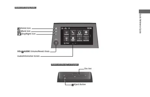
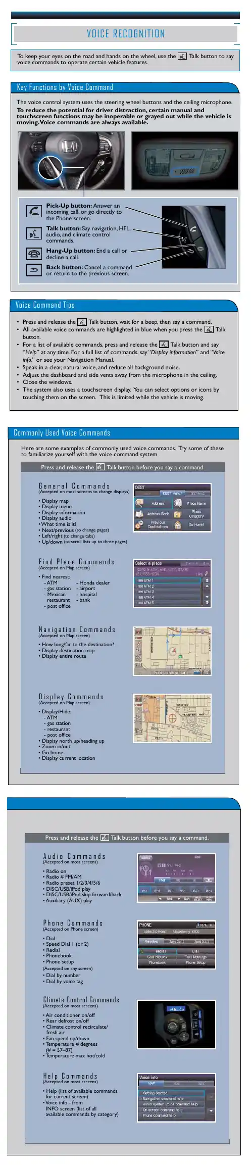
Quick Reference GuideVOL / AUDIO(Home) Icon (Back) Icon(Day/Night) Icon(Eject) ButtonDisc SlotModels with Blu-ray or CD playerTMFeaturesAbout Your Audio SystemThe audio system features AM/FM radio and SiriusXM ® Radio * service. It can also play audio CDs *, USB flash drives, and iPod, iPhone, iPad * and Bluetooth ® devices.You can operate the audio system from the buttons * and knobs on the panel, the remote controls on the steering wheel, or the icons on the touchscreen interface *.1About Your Audio SystemiPod, iPad, iPhone and iTunes are trademarks of Apple Inc.State or local laws may prohibit the operation of handheld electronic devices while operating a vehicle.Video CDs, DVDs *1, Blu-ray Discs *1, and 3-inch (8-cm) mini CDs are not supported.*1: Models with CD playerSiriusXM ® Radio*is available on a subscription basis only. For more information on SiriusXM ® Radio *, contact a dealer.SiriusXM ® Radio * is available in the United States and Canada, except Hawaii, Alaska, and Puerto Rico.SiriusXM ®* is a registered trademark of SiriusXM Radio *, Inc.After you set the power mode to VEHICLE OFF, you can use the audio system for up to 30 minutes per driving cycle, or until opening the driver’s door.However, whether you can continue using the audio system depends on the battery condition. Repeatedly using this feature may drain the battery.Models with Blu-ray TM or CD playerModels with Display AudioRemote ControlsiPodUSB Flash Drive*1:Models with color audio system *2:Models with Display Audio*1*2uu Audio System u Audio Remote ControlsFeatures Allow you to operate the audio system while driving. The information is shown onthe driver information interface.+/-(Volume) BarPress +: To increase the volume.Press -: To decrease the volume.1Audio Remote ControlsSome modes appear only when an appropriatedevice or medium is used.Depending on the Bluetooth® device you connect,some functions may not be operated.Press the (back) button to go back to theprevious screen or cancel a command.Press the (home) button to go back to the home ENTER Button+/-Bar///Buttons34screen of the driver information interface.You can show or hide the audio mode icons, orchange the order of the icons.uu Audio System u Audio Remote ControlsFeatures////ENTER Buttons•When selecting the audio modePress or to select Now Playing on the home screen of the driver information interface, and then press the ENTER button.Pressor : To cycles through the audio modes as follows:Android Auto/Apple CarPlay →SiriusXM ®*→Rear Entertainment *→AUXInput →AM →Bluetooth ® Audio →Social Playlist →FM →My Honda Music →USB/iPod →CD *•When listening to the radio Press : To select the next preset radio station.Press : To select the previous preset radio station.Press and hold : To select the next strong station.Press and hold : To select the previous strong station.•When listening to a CD *, iPod, USB flash drive, My Honda Music, or Bluetooth ®AudioPress : To skip to the next song.Press : To go back to the beginning of the current or previous song.•When listening to an iPod, USB flash drive, My Honda Music, Bluetooth ® Audio,or Apple CarPlay Press and hold /: To move rapidly within a song.343434uu Audio System Basic Operation u Audio/Information ScreenFeatures Audio/Information ScreenDisplays the audio status and wallpaper. From this display, you can go to varioussetup options.■Using the audio/information screenSelect to go to the home screen.Select the following icons on the home screen or after selecting All Apps.■Switching the Display1Audio/Information ScreenTouchscreen Operation•Use simple gestures - including touching, swiping,and scrolling - to operate certain audio functions.•Some items may be grayed out during driving toreduce the potential for distraction.•You can select them when the vehicle is stopped oruse voice commands.•Wearing gloves may limit or prevent touchscreenresponse.You can change the touchscreen sensitivity setting.(Home) IconAll Appsuu Audio System Basic Operation u Audio/Information ScreenFeatures■PhoneDisplays the HFL information.■Trip ComputerDisplays the trip computer information.•Current Drive tab: Displays the current trip information.•Trip A /Trip B tab: Displays information for the current and three previous drives.The information is stored every time you reset Trip A/B.To reset Trip A/B, select Reset .To change the setting of how to reset Trip A/B, select Settings , then select Trip A Reset Method or Trip B Reset Method .■ClockDisplays the clock.■System UpdatesUpdates the software version of the audio system.■FM/AM/Sirius XM /CD /USB/Bluetooth Audio/AUX Input/My Honda**Music/Social PlaylistDisplays the each audio information.■SettingsEnters the customizing menu screen.uu Audio System Basic Operation u Audio/Information ScreenFeatures ■Navigation*Displays the navigation screen.■HondaLinkDisplays the HondaLink® screen.■Apple CarPlay/Android AutoDisplays the Apple CarPlay or Android Auto.■MessagesDisplays the text message screen.■CabinTalk*Displays the CabinTalk screen.■CabinWatch*Displays the CabinWatch screen.■Rear Entertainment*Displays the rear audio screen.uu Audio System Basic Operation u Audio/Information Screen■AT&T Hotspot*Displays the AT&T Hotspot screen.■File ManagerDisplays the file manager screen.Featuresuu Audio System Basic Operation u Audio/Information ScreenFeatures Some of the audio system’s apps can be updated wirelessly when connected via Wi-Fi, or Bluetooth® in conjunction with the HondaLink® app installed on a compatibleiOS or Android device. If an update is available, a notification is displayed at the topof the screen with the respective app’s update icon.■To update an app:1.A notification appears and notifies you of aupdate message on the header area.2.Select the system status icon, and thenselect the software update notificationfrom the list.■Updating Apps1Updating AppsThe wireless updates are for the apps on the audiosystem only.To update compatible apps on your iPhone orAndroid phone, please visit the App Store or GooglePlay Store, respectively.uu Audio System Basic Operation u Audio/Information ScreenFeatures3.Select Download .4.Select OK .u A notification appears on the screen if the update is successful. Select OK .u Restart the engine for the update to be applied.12:34。
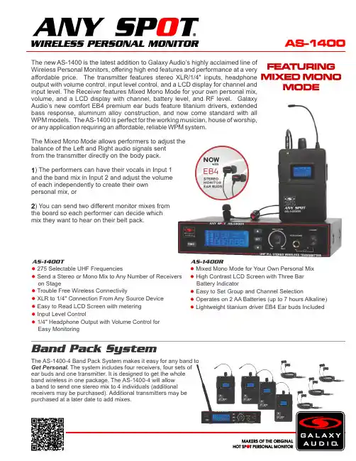
The new AS-1400 is the latest addition to Galaxy Audio’s highly acclaimed line of Wireless Personal Monitors, offering high end features and performance at a very affordable price. The transmitter features stereo XLR/1/4" inputs, headphone output with volume control, input level control, and a LCD display for channel and input level. The Receiver features Mixed Mono Mode for your own personal mix, volume, and a LCD display with channel, battery level, and RF level. Galaxy Audio’s new comfort EB4 premium ear buds feature titanium drivers, extended bass response, aluminum alloy construction, and now come standard with all WPM models. The AS-1400 is perfect for the working musician, house of worship, or any application requiring an affordable, reliable WPM system.The Mixed Mono Mode allows performers to adjust thebalance of the Left and Right audio signals sentfrom the transmitter directly on the body pack.1) The performers can have their vocals in Input 1and the band mix in Input 2 and adjust the volumeof each independently to create their ownpersonal mix, or) You can send two different monitor mixes from2the board so each performer can decide which mix they want to hear on their belt pack.275 Selectable UHF Frequencies● Send a Stereo or Mono Mix to Any Number of Receivers● on StageTrouble Free Wireless Connectivity● XLR to 1/4 Connection From Any Source Device●" Easy to Read LCD Screen with metering● Input Level Control● 1/4 Headphone Output with Volume Control for●" Easy Monitoring Mixed Mono Mode for Your Own Personal Mix ● High Contrast LCD Screen with Three Bar ● Battery Indicator Easy to Set Group and Channel Selection ● Operates on 2 AA Batteries (up to 7 hours Alkaline)● Lightweight titanium driver EB4 Ear buds Included ●The AS-1400-4 Band Pack System makes it easy for any band toGet Personal. The system includes four receivers, four sets ofear buds and one transmitter. It is designed to get the wholeband wireless in one package. The AS-1400-4 will allowa band to send one stereo mix to 4 individuals (additionalreceivers may be purchased). Additional transmitters may bepurchased at a later date to add mixes.AS-1400T AS-1400RSpecifications subject to change without notice.V20170502601 E. Pawnee Wichita, KS 67211 316. 263.2852 FAX 316.263.0642 Distributed in Canada by Audio Distributors International (ADI ) 1275 Newton, unit 6 Boucherville, QC J4B 5H2 Canada 450.449.8177 FAX 450.449.8180TradeLink America, LLC.Distributed outside the United States by 230 Kings Mall Ct., Suite 182 Kingston, NY 12401 ******************************.845.246.6200FAX1.845.746.9070AS-1400 SystemBand:UHFFrequencies: 275 Selectable FrequenciesTransmitter Output Level: 30 mWOperating Range: Under Typical Conditions 300' (92m)Note: actual range depends on RF signal absorption,reflection, interference, and battery characteristicsAudio Frequency Response: +/-3dB 40Hz~16kHzTotal Harmonic Distortion: < 0.4% @ 1kHzSignal to Noise: >105dBAMaximum Deviation Range: +/-68kHzDynamic Range: >90dB A-weightedOperating Temperature: Range 14ºF to 122ºF (-10º C to +50º C)Note: battery characteristics may limit this rangeIncluded Accessories: Power Supply, EB4 Ear Buds, Antenna,Single/Dual Rack Ears, Quick Start GuideAS-1400T TransmitterMain Frame Size: EIA STANDARD 1/2UModulation Mode: FM Stereo ModulationRF Output: 30 mWMax Audio Input Level: +6dBVGain Adjustment Range: 33dBAudio Input: Line Level x 2, XLR/ 1/4" Combo JackXLR input: BalancedPin: 1 Ground (cable shield)Pin: 2 Audio +Pin: 3 No Audio -Audio Output: 1/4" Headphone OutDimensions: 1.7" x 8.2" x 7.1" (44 x 209 x 180 mm) (HxWxD)Weight: 37.4 oz. (1,060 g)12-18 V DC at 300mA supplied byPower Supplied By:external power supplyAS-1400R Body Pack ReceiverAudio Output Level: 100mWSensitivity: 6dBμV, S/N>60dBStereo Separation: 45db (at 1kHz)Output Connector: 1/8" (3.5mm) Stereo Earphone ConnectorDimensions: 4.33" x 2.56" x 0.87" (110 x 65 x 22 mm) (HxWxD)Weight: 5.12 oz (145 g) without batteries2 (AA) size alkaline or rechargeable batteriesPower Supplied By:Battery Life: About 7 hours (alkaline)。
QS6006寸2路全频专业扬声器系统用户手册CN UM-QS600-20170808Ve r B感谢您购买 产品!请仔细阅读本手册,它将帮助你妥善设置并运行您的系统,使其发挥卓越的性能。
并保留这些说明以供日后参照。
警告:为了降低火灾与电击的风险,请不要将产品暴露在雨中或潮湿环境中。
警告:为了降低电击的风险,非专业人士请勿擅自拆卸该系统。
仅供专业人士操作。
等边三角形中的闪电标记,用以警示用户该部件为非绝缘体,系统内部存在着电压危险,电压。
可能足以引起触电。
可能足以引起触电如系统标有带惊叹号的等边三角形,则是为提示用户严格遵守本用户指南中的操作与维护规定。
注意:请勿对系统或附件作擅自的改装。
未经授权擅自改装将造成安全隐患。
警告:燃不得将明火源(如点的蜡烛)放在器材上面。
1. 请先阅读本说明。
2. 保留这些说明以供日后参照。
3. 注意所有警告信息。
4. 遵守各项操作指示。
5. 不要在雨水中或潮湿环境中使用本产品。
6. 不要将产品靠近热源安装,例如暖气管、加热器、火炉或其它能产生热量的装置(包括功放机 )。
7. 不要破坏极性或接地插头的安全性设置。
如果提供的插头不能插入插座,则应当请专业人员更换插座。
8. 保护好电源线和信号线,不要在上面踩踏或拧在一起(尤其是插头插座及穿出机体以外的部分 )。
9. 使用厂商规定及符合当地安全标准的附件。
10.雷电或长时间不使用时请断电以防止损坏产品。
12. 不要让物体或液体落入产品内——它们可能引起火灾或触电。
13. 请注意产品外罩上的相关安全标志。
. 仅与厂商指定或与电器一同售出的推车、架子、三脚架、支架或桌子一起使用。
推动小车电/器时,应谨防翻倒。
11注意事项产品的安装调试须由专业人士操作。
在使用非本厂规定的吊装件时,要保证结构的强度并符合当地的安全规范。
警告:1扬声器及扬声器系统的产品有限保修期为自正式购买日起的3年。
由于用户不合理的应用而导致音圈烧毁或纸盆损坏等故障,不包含于产品保修项目。

160SLStereo Compressor/LimiterOwner’s ManualRefer all servicing to qualified service personnel. Servicing is required when the apparatus has been damaged in any way, such as power-supply cord or plugManufacturer’s Name: dbx Professional Products Manufacturer’s Address: 8760 S. Sandy Parkway Sandy, Utah 84070, USA declares that the product:Product name: dbx 160SL N ote: Product name may be suffixed by the letters-EU. Product option: None conforms to the following Product Specifications:Safety: IEC 60065 -01+Amd 1 EMC: EN 55022:2006 (N/A; Analog Product) I E C61000-4-2 I E C61000-4-3 I E C61000-4-4 I E C61000-4-5 I E C61000-4-6 I E C61000-4-8 I E C61000-4-11Supplementary Information:The product herewith complies with the requirements of the:Low Voltage Directive 2006/95/EC EMC Directive 2004/108/EC.RoHS Directive 2002/95/EC WEEE Directive 2002/96/EC With regard to Directive 2005/32/EC and EC Regulation 1275/2008 of 17 December 2008, this product is designed, produced, and classified as Professional Audio Equipment and thus is exempt from this Directive.Roger Johnsen Director, Engineering Signal Processing 8760 S. Sandy Parkway Sandy, Utah 84070, USA Date: August 16, 2011European Contact: Your local dbx Sales and Service Office or Harman Signal Processing8760 South Sandy Parkway Sandy, Utah 84070 USA Ph: (801) 566-8800Fax: (801) 568-7583DECLARATION OF CONFORMITY eLectroMaGnetIc coMPatIBILItythis unit conforms to the product specifications noted on the Declarationof Conformity . operation is subject to the following two conditions:• t his device may not cause harmful interference, and• t his device must accept any interference received, includinginterference that may cause undesired operation.operation of this unit within significant electromagnetic fields should beavoided.• use only shielded interconnecting cables.u.K. MaInS PLuG WarnInGA molded mains plug that has been cut off from the cord is unsafe.discard the mains plug at a suitable disposal facility.NEVER UNDER ANY CIRCUMSTANCES SHOULD YOUINSERT A DAMAGED OR CUT MAINS PLUG INTO A 13AMP POWER SOCKET.do not use the mains plug without the fuse cover in place.replacement fuse covers can be obtained from your local retailer.replacement fuses are 13 amps and must be AstA approved toBs1362.Operatingto your systemOperatingto your systemOperatingSpecifications Manual DesignBlock mounted above or below anything that doesn’t create excessive heat, since it requires no specialventilation. Ambient temperatures should not exceed 113°F (45°C) when equipment• M ake connections via XLR connectors.T wo Basic Compressor Setups:A : C hannel One shows processing of a groupFigure 4to your systemto your systemOperating-20-20DesignBlock ControlsThis panel is removed when an output option card is installed in your 160SL. Connecting a custom designed digital output module in the option portBU and S/PDIF output capabilities for the 160SL. The digital outputs of the 160SL operate simultaneously with the analog outputs, providing the possibility of running to three different devices at the same time: analog, AES/EBU, and S/PDIF. For more information on the digital output option, contact dbx customer service.17TechnicalSpecifications Using PeakStop The Stop Level control sets the maximum peak output level of the 160SL irrespective of any other control. PeakStop consists of a sophisticated voltage-controlled Instantaneous Transient Clamp that produces a minimum of audible distortion. It rounds the corners of a peak rather than cutting it off sharply, as “clippers” do. By making a signal’s leading and trailing edges curved instead of sharp corners, it reduces the amount of higher odd-order, offensive-sounding harmonics that conventional clipping causes.Connection Installation Technical1921Operating23OperatingDesign25OperatingTechnical27Operating8760 South Sandy Pkwy.Sandy, Utah 84070Phone: (801) 568-7660Fax: (801) 568-7662Int’l Fax: (603) 672-4246Questions or comments?E•mailusat:*******************or visit our website at:5018577-A04/09/12。

Please Note: All specifications and improvements to and in the design of this unit and this manual are subject to change at any time without any prior written or published noticed.6122 S. Eastern AveLos Angeles Ca. 90040www.americanaudio.eu1.1.Table of Contents (3)2.Before We Start (5)2.1 What's New to myDMX 2.0 (5)2.2 The myDMX 2.0 Package (7)2.3 Fixture Profiles (8)3.Getting Started (9)3.1 Installation (9)3.2 Setup (10)3.3 Editor (13)3.4 User (16)3.4.1 Live Edits (17)4.Scene Builder (18)4.1 Arranging Fixtures (18)4.2 Controlling Fixtures (20)4.3 Effects (23)5.Other Features (26)5.1 Easy Remote (coming soon) (26)2.Welcome to myDMX 2.0 – a powerful and easy to use DMX lighting control app for PC and Mac. This manual will guide you through using the software. For a quick overview of the software jump straight to the topics in the chapter Getting Started on page 9.2.1W HAT'S N EW TO MY DMX2.0The myDMX 2.0 has been re-built from the ground up. This chapter will give an overview of the most important new features.We have been asked to develop a Mac version of the software for many years – myDMX 2.0 is now PC and Mac compatible.2.1.1 N EW D ESIGNThe software features a new design, which includes new icons, faders, colors and preset components allowing for a quicker and more pleasant workflow.Quickly jump to a color or position with the new popup preset components and change the scene color on the User screen.2.1.2 T HE S CENE B UILDERThe Scene Builder allows you to do everything you used to do with the original Effects Generator and more.Arrange lighting fixtures, draw effects directly onto fixtures and set your effects in real-time.The ‘Linear Fan’ effect allows you to create color gradients and position fans.2.1.3SSL2F IXTURE P ROFILE F ORMATSSL2 fixture profiles allow more information to be stored about the personality of a lighting fixture. This allows for quicker and easier programming. For example, if you have an LED bar with several segments, you can control each segment individually whilst still having global control of master dimmer and macro channels.2.2T HE MY DMX2.0P ACKAGE2.2.1W HAT'S IN THE BOXYour package should include the following:CD with the softwareUSB-DMX interfaceUSB cableThe latest software versions and user manuals are available from our website.2.2.2S OFTWAREThe following software is included:myDMX 2.0 - DMX lighting programming app (PC and Mac)Scan Library – Used to build your own fixture profiles (PC only)EasyView – A real-time 3D visualizer (PC only)Hardware Configuration Tools –A USB-DMX interface management app (PC only) Easy Remote – Remote control of myDMX 2.0(iPad/Android Tablet)2.3 F IXTURE P ROFILESAll of the attributes of a DMX device are saved in a special file called the “Fixture Profile” or .SSL2 file. The more accurate the fixture profile, the easier it will be to program your lighting with myDMX 2.0.If you have an incomplete fixture profile, myDMX 2.0 will not understand the lights you want to control and therefore it will be more difficult for you to program your lighting fixtures.There is a profile for almost every fixture on the market. Fixture profiles can be created and edited with the "Scan Library" editor software. For more details on how to make Scan Library profiles, see chapter 2.2.2 Software on page 7.3.3.1I NSTALLATIONInsert the software installation CD into the CD drive of your computer, or download the software from our website.Double click the setup icon to install the software.Follow the installer instructions.The USB interface drivers will be installed during the software installation. When installing on Windows, you may receive a warning message saying that the drivers hav e not been digitally signed. Press ‘Continue Anyway’.Once the installation is complete, connect the USB interface. Windows systems will run a second device driver installation. Once you see a message bubble on the taskbar to say that the driver has been installed successfully, you are ready to start the myDMX 2.0 software.3.2S ETUPTo begin with, the software needs to be told which lighting fixtures are being used. Select your lighting fixture from the list of manufacturers on the left. If you are looking to add an RGB, RGBD, RGBW, RGBY or Single channel fixture, select the _GENERIC folder at the top. If you do not see your lighting fixture in the list, you will need to make it yourself using the Scan Library editor (PC only), or contact us and we will build the profile for you.To add your lighting fixture, drag and drop it onto the DMX patch table, or select the number of fixtures and starting channel in the bottom left and select patch. Fixtures can be moved within the DMX patch by dragging and dropping.If you are looking to add a matrix of lighting fixtures such as an RGB wall or dancefloor, patch the total number of lighting fixtures here and refer to chapter 4.1 Arranging Fixtures on page 18 for more information.3.2.1A DDRESSING YOUR L IGHTING F IXTUREEach lighting fixture must be given a unique number or “Address”. The address is normally set via an LED display or Dip Switches on the actual lighting fixture. Hover over a fixture to know the address and click the fixture to see the dip switches required to set this address. For example, this lighting fixture is set to address 22.For more information on setting the address on a lighting fixture, refer to the fixture manufacturers’ manual.3.2.2L IST V IEWTo change individual fixture properties, select ‘List View’.The following options are available:Shortcut - To control the selected channel with the mouse, select a keyboard shortcut hereFade - Enables and disables fading of the channel. For example, you may wish to ignore all fade commands on a gobo channelDimmer - Defines a dimmer channel (when the dimmer % value of a step is changed, this channel will be changed)Invert X - Inverts the X channel, so when the fader is at 0, the software will output 255Invert Y - Inverts the Y channel, so when the fader is at 0, the software will output 255X/Y - Swaps the X and Y channels3.3E DITOR3.3.1C ONTROLLING C HANNELSfader with the mouse to change the value.To change the value of the same channel type on everyfixture, hold shift. For example, to change the color of everyfixture, hold shift and move the color fader. Notice that theDMX output value is displayed at the top of the fader.MyDMX 2.0 features a range of preset components to helpyou to quickly adjust a channel. To access the component,click at the top of the channel where the preset/color isdisplayed. For example, clicking at the top of a color channelshows a color wheel.Clicking on the cursor will allow you to drag it around thecolor wheel. Notice that the RGB values are shown. Clickingon the color wheel and dragging up with the mouse willmove the cursor clockwise, dragging down will move thecursor anti clockwise.With the XY grid, clicking on the center point will allow youto quickly set an XY position. Clicking on a blank space in thegrid will allow you to slowly move the position.3.3.2S CENES AND S TEPSAll programming is made with scenes and steps. A step is a static ‘Look’ which contains one value for each channel. Several s teps make up a scene. Scenes can be created by clicking the top left icon in the scene area.Once values have been set, steps can be created here (1). When a new step is created, all faders are set to 0. To copy the current step's values, click here (2). Double click the Fade time, Wait time or dimmer value to modify. To modify several steps at the same time, hold control (PC) / command (Mac) to select multiple steps. To select a range of steps, select the first step of the range, hold shift and then select the final step of the range.You can preview your scene by clicking the play button.3.3.3S CENE S ETTINGSDouble click a property to edit. For example, to change the name of a scene:1.Double click the name2.Type the new name3.Press the Return keyThe following properties can be changed:# - If this is selected, the scene will be included in the showLoops - Set the number of times a scene should repeatNext - Set where you want to scene to go when it reaches the end (make sure a number of loops has been set first!)Enable/Disable Fade - When this is selected, the scene will fade in using the fade time of the first stepTrigger - Add a keyboard shortcut key to trigger the scene3.4U SERThe User screen is where you run your show. Click a scene to activate it. If you want your scene to listen to the Loop and Next properties, make sure that the Play button is selected here.It is possible to change the color of a scene by right clicking the scene.3.4.1L IVE E DITSIt is possible to override scenes by moving the faders.There are two options:LTP - Latest takes priority: The fader value will override the sceneHTP - Highest Takes Priority: If the fader value is higher than the value within the activated scene, it will override the sceneTo set up L TP or HTP, make sure that it is enabled within the ‘User Options’ menu and then click the AUTO button at the bottom of the ch annel you want to override.4. 4.1 A RRANGING F IXTURESThe scene builder allows you to quickly and easily build advanced scenes and create effects without the need to set each fader and step manually.It replaces the effects generator and color manager in the previous software version.Create a new scene and click here to open the scene builder.4.1.1 S ELECTION M ODEWhen the scene builder is opened, you will see your lighting fixtures on the left. Each square represents a lighting fixture. Click and drag the squares to position the lighting fixtures. Hold Control (PC) / Command (Mac) to select multiple fixtures.There are 3 tools to help with fixture selection:Rectangle - Draw a rectangle around the fixtures to select (like selecting files inside Explorer/Finder)Lasso - Draw a perimeter around a set of fixtures to select the fixtures within the chosen perimeterDrag Over - Any fixtures within a drawn shape will be selectedNotice that as fixtures are selected, a number appears. This is the order in which any curve or linear fan effect will be created.4.1.2G ROUPSGroups can be created to help quick recall of fixture selections. To create a group, select the fixtures to be included inside the group and then select the + button.4.1.3 M ATRIXESClick here to create a matrix – myDMX 2.0 will automatically position your lighting fixtures into a matrix.Select the arrow to define a custom width and height of the matrix.4.2 C ONTROLLING F IXTURESOnce you have selected the lighting fixtures you wish to control, all common presets will be shown here. To view only the presets of a particular fixture type, select the appropriate tab.If you have no fixtures selected, you can draw a preset onto a fixture: 1. Select the Pen tool2. Select the presets you want to change3.Click on the fixtures you want to update4.2.1 C OLOR W HEELThe color wheel offers several ways to change the color:Click the cursor and drag around the color wheel to choose a color Click on the color wheel to jump to one of the 6 preset colorsClick on the color wheel and drag up and down to move slowly around the color wheel Select the center sections to modify the brightness and saturation Click in the center of the color wheel to choose a color with a standard color picker or insert RGB values4.2.2 XY G RIDThe XY grid allows you to modify the pan/tilt channels of a fixture (uPan and uTilt are automatically calculated). Click the center point and drag to move the positionClick a blank space in the grid and drag to slowly move the position, use the scroll wheel of your mouse to adjust the precisionSelect the horizontal and vertical bars to adjust only the pan or tilt4.2.3 B EAM O NClicking the beam on button will enable the default preset of each selected fixture. For example, on a moving head this may be ‘Shutter Open’, ‘Iris Open’ and ‘Dimmer 100%’.4.2.4 L INEAR F ANThe linear fan function allows you to define a range by selecting a start and end point.The preset range will then be applied across the selected lighting fixtures. This is a great way to create color gradients and position fans.1. Click here to enable/disable the Linear Fan function2. Click the down arrow to select the fan type3. Click on the component to select the start and end range4. Select the range and drag up and down to move the range4.3E FFECTS4.3.1C OLOR E FFECTTo add an effect, select the effects tab and click the FX icon. Select 'ColorEffect'. A rectangle will appear in the upper left corner playing a rainboweffect. Drag and drop this over your lighting fixtures. The effect can beresized by dragging the corners.To modify a color effect, select the effect type and change the properties. It ispossible to add many effects at the same time by simply choosing anothereffect from the menu.4.3.2P OSITION E FFECTscanners and moving head lighting fixtures.Select the fixtures you want to control, select ‘Position Effect’ fromthe FX menu and then select a starting shape.The shape can be altered by clicking on a point and dragging.Phasing will add a delay on each fixture.4.3.3 C URVE E FFECTThe curve effect tool allows you to apply a dimming curve to any channel. Select 'Curve Effect' from the FX menu and select the fixtures you wish to control. The following properties are available:Rate - Changes the speed of the effect. More wave cycles will be added Size - Changes the height of the wavePhase - Moves the wave forward and backward, consequently changing the starting pointOffset - Moves the wave up and down Phasing - Adds a delay to each fixtureThe curve effects can be stacked to create many interesting patterns.4.3.4 G ENERATE AN E FFECTYou can remove an individual effect by clicking on the trashcan icon. The whole effect can be cleared by selecting the cancel icon (to the leftof the tick icon). Select the tick icon to generate the effect.5.5.1E ASY R EMOTE (COMING SOON)Easy Remote is an iPad and Android tablet app which allows you to control myDMX 2.0 over a WiFi network. The app will be available soon!Follow us on:/americandj/americandj/adjlighting©American Audio® World Headquarters6122 S. Eastern Ave. Los Angeles, CA 90040 USATel: 323-582-3322 Fax: 323-582-3311Web: E-mail:*********************American DJ EuropeJunostraat 26468 EW KerkradeNetherlands*******************www.americandj.euTel: +31 45 546 85 00Fax: +31 45 546 85 99。
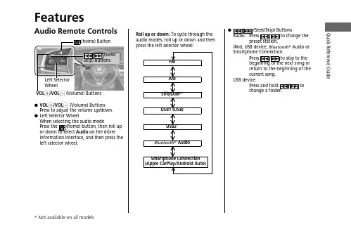
Quick Reference GuideFeaturesAudio Remote Controls●VOL +/VOL - (Volume) Buttons Press to adjust the volume up/down.●Left Selector WheelWhen selecting the audio mode Press the (home) button, then roll up or down to select Audio on the driver information interface, and then press the left selector wheel.Left Selector WheelVOL +/VOL - (Volume) ButtonsFMAM SiriusXM ®*USB1 (USB)USB2*Bluetooth ® AudioSmartphone Connection (Apple CarPlay/Android Auto)Roll up or down: To cycle through the audio modes, roll up or down and then press the left selector wheel:●/ (Seek/Skip) Buttons Radio:Press / to change theiPod, USB device, Bluetooth ® Audio or Smartphone Connection:Press / to skip to the beginning of the next song or return to the beginning of the current song.USB device:Press a nd hold / to change a folder.Quick Reference Guide Audio System(Back) Button(Day/Night) Button(Seek/Skip) Button(Seek/Skip) Button V OL/ButtonButton*(Ma p) Button*Features About Your Audio SystemThe audio system features AM/FM radio and SiriusXM® Radio* service. It can alsoplay USB flash drives, iPod, iPhone and Bluetooth® devices.You can operate the audio system from the buttons and knobs on the panel, theremote controls on the steering wheel, or the icons on the touchscreen interface.1About Your Audio SystemiPod®, iPhone® and iTunes are trademarks of AppleInc.State or local laws may prohibit the operation ofhandheld electronic devices while operating avehicle.SiriusXM® Radio is available on a subscription basis*only. For more information on SiriusXM® Radio*,contact a dealer.SiriusXM® Radio* is available in the United States andCanada, except Hawaii, Alaska, and Puerto Rico.SiriusXM®* is a registered trademark of SiriusXMRadio*, Inc.Remote ControlsiPodUSB Flash Driveuu Audio System u USB PortsFeaturesUSB Ports■In the center pocket ()The USB port(s) (2.5A) is/are for charging devices, playing audio files and connectingcompatible phones with Apple CarPlay or Android Auto.u To prevent any potential issues, be sure to use an Apple MFi Certified Lightning Connector for Apple CarPlay, and for Android Auto, the USB cables should be certified by USB-IF to be compliant with USB 2.0 Standard.■In the center pocket ()*The USB port (2.5A) is only for charging devices.u You cannot play music even if you have connected music players to it.*1: Models without wireless Apple CarPlay and wireless Android Auto 1USB Ports•Do not leave the iPod or USB flash drive in the vehicle. Direct sunlight and high temperatures may damage it.•We recommend that you use a USB cable if you are attaching a USB flash drive to the USB port.•Do not connect the iPod or USB flash drive using a hub.•Do not use a device such as a card reader or hard disk drive, as the device or your files may be damaged.•We recommend backing up your data before using the device in your vehicle.•Displayed messages may vary depending on the device model and software version.The USB port can supply up to 2.5A of power. It does not output 2.5A unless the device requests.For amperage details, read the operating manual of the device that needs to be charged.Under certain conditions, a device connected to the port may generate noise to the radio station you are listening to.USB charge*2*1uu Audio System u USB PortsFeatures ■Rear of the center console*The USB ports (2.5A) are only for charging devices.u You cannot play music even if you haveconnected music players to them.uu Audio System u Audio System Theft ProtectionAudio System Theft ProtectionThe audio system is disabled when it is disconnected from the power source, such aswhen the battery is disconnected or goes dead. In certain conditions, the systemmay display a code entry screen. If this occurs, reactivate the audio system.■Reactivating the audio system1.Set the power mode to ON.2.Turn on the audio system.3.Press and hold the audio system power knob for more than two seconds.u The audio system is reactivated when the audio control unit establishes aconnection with the vehicle control unit. If the control unit fails to recognizethe audio unit, you must go to a dealer and have the audio unit checked.Featuresuu Audio System u Audio Remote ControlsFeatures Audio Remote ControlsAllow you to operate the audio system while driving. The information is shown onthe driver information interface or head-up display*.VOL+/VOL- (Volume) ButtonsPress VOL+: To increase the volume.Press VOL-: To decrease the volume.Left Selector Wheel•When selecting the audio modePress the (home) button, then roll up or down to select Audio on the driverinformation interface, and then press the left selector wheel.1Audio Remote ControlsSome modes appear only when an appropriatedevice or medium is used.Depending on the Bluetooth® device you connect,some functions may not be available.Press the (back) button for the driverinformation interface to go back to the previousscreen or cancel a command.Press the (home) button to go back to the homescreen of the driver information interface.VOL+/VOL- (Volume) ButtonsLeft Selector Wheel(home) Button/(Seek/Skip)Buttons(back)Buttonuu Audio System u Audio Remote ControlsFeaturesRoll up or down:FMAM SiriusXM ®*USB1 (USB)USB2*Bluetooth ® AudioSmartphone Connection (Apple CarPlay/Android Auto)To cycle through the audio modes, roll up or down and then press the left selector wheel:uu Audio System u Audio Remote ControlsFeatures/ (Seek/Skip) Buttons•When listening to the radioPress :To select the next preset radio station.Press :To select the previous preset radio station.Press and hold : To select the next strong station.Press and hold : To select the previous strong station.•When listening to an iPod, USB flash drive, or Bluetooth® Audio, or Smartphone ConnectionPress :To skip to the next song.Press :To go back to the beginning of the current or previous song.•When listening to a USB flash drivePress and hold : To skip to the next folder.Press and hold : To go back to the previous folder.FeaturesPress to go to the home (Back) Button: Press to go back to the previous display when it is displayed./ (Seek/Skip) Buttons: Press to change songs.(Clock) Button *: Press to display the clock*: Press to display the map (Phone) Button: Press to display the phone screen.(Audio) Button: Press to display the current audio information.SOURCE Button: Press to display the sourceselect screen.Selector Knob: Rotate left or right to scrollPress to change Press once and select or to make an adjustment.u Each time you press , the mode switches among the daytime mode, nighttime mode and off mode.1Audio System Basic OperationThese indications are used to show how to operate Rotate select.Press to enter.Selector KnobWhen the list is not displayed, songs, frequency, etc. can be changed.While connected to Apple CarPlay, it changes as follows:•Pressing the Phone Button, display the Apple CarPlay phone screen.•Pressing the Audio Button, display the Apple CarPlay audio screen.uu Audio System Basic Operation u Audio/Information ScreenFeatures Audio/Information ScreenDisplays the audio status and wallpaper. From this display, you can go to varioussetup options.■Using the audio/information screenPress the button to go to the home screen.Select the following icons on the home screen or after selecting All Apps.■PhoneDisplays the HFL information.■Switching the Display1Audio/Information ScreenTouchscreen Operation•Use simple gestures - including touching, swiping,and scrolling - to operate certain audio functions.•Some items may be grayed out during driving toreduce the potential for distraction.•You can select them when the vehicle is stopped oruse voice commands.•Wearing gloves may limit or prevent touchscreenresponse.You can change the touchscreen sensitivity setting.All Appsuu Audio System Basic Operation u Audio/Information ScreenFeatures■Trip ComputerDisplays the trip computer information.•Current Drive tab: Displays the current trip information.•Trip A /Trip B tab: Displays information for the current and three previous drives.The information is stored every time you reset Trip A/B.To reset the Trip A/B, select Settings , then select Delete Trip History .To change the setting of how to reset Trip A/B, select Settings , then select “Trip A” Reset Timing or “Trip B” Reset Timing .■ClockDisplays the clock.■System Updates *Updates the software version of the audio system.■FM/AM/Sirius XM /USB1 (USB)/USB2/Bluetooth Audio**Displays information for each audio format.■SettingsEnters the customizing menu screen.■Navigation *Displays the navigation screen.uu Audio System Basic Operation u Audio/Information ScreenFeatures ■HondaLinkDisplays the HondaLink screen.■Apple CarPlay/Android AutoDisplays the Apple CarPlay or Android Auto screen.■MessagesDisplays the text message screen.■AT&T Hotspot*Displays the AT&T Hotspot screen.■Compass*Displays the compass screen.uu Audio System Basic Operation u Adjusting the SoundFeatures Adjusting the Sound1.Press the button.2.Select an audio source icon.3.Select Sound.4.Select the setting you want.5.Select Save.Select an item from the following choices:•Bass / Treble: Treble, Midrange, Bass,Subwoofer*•Balance / Fader: Balance, Fader•DTS Neural Surround*: DTS NeuralSurround TM•Speed Volume Compensation: SpeedVolume Compensation (SVC)1Adjusting the SoundThe SVC adjusts the volume level based on thevehicle speed. As you go faster, audio volumeincreases. As you slow down, audio volumedecreases.You can also adjust the sound the followingprocedure.1.Press the button.2.Select .3.Select Sound.To reset each setting for Bass / Treble, Balance /Fader, DTS Neural Surround* and Speed VolumeCompensation select Default.。
OWNER’S GUIDE2READ FIRST!Important Safety Precautions!1.Read these instructions.2.Keep these instructions.3.Heed all warnings.4.Follow all instructions.5.Do not use this apparatus near water.6.Clean only with a dry cloth.7.Do not block any ventilation open-ings. Install in accordance with the manufacturer’s instructions.8.Do not install near any heat sources such as radiators, heat registers,stoves or other apparatus (including amplifiers) that produce heat.9.Do not defeat the safety purpose of the polarized or grounding-type plug.A polarized plug has two blades with one wider than the other. A ground-ing-type plug has two blades and a third grounding prong. The wide blade or the third prong are provided for your safety. If the provided plug does not fit into your outlet, consult an electrician for replacement of the obsolete outlet.10.Protect the power cord from being walked on or pinched, particularly at plugs, convenience receptacles and the point where they exit from the apparatus.11.Only use attachments/accessories specified by the manufacturer.e only with the cart, stand, tri-pod, bracket or table specified by the manufacturer or sold with the appa-tip-over.13.Unplug this apparatus during light-ning storms or when unused for long periods of time.14.Refer all servicing to qualified service personnel. Servicing is required when the apparatus has been damaged in any way, such as power-supply cord or plug is dam-aged, liquid has been spilled or objects have fallen into the appara-tus, the apparatus has been exposed to rain or moisture, does not operate normally, or has been dropped.15.Do not use attachments not recommended by the product manufacturer, as they may cause hazards.16.This product should be operated only from the type of power source indicated on the marking label. If you are not sure of the type of power sup-ply to your home, consult your prod-uct dealer or local power company.For products intended to operate from battery power, or other sources, refer to the operating instructions.17.If an outside antenna or cable system is connected to the product, be sure the antenna or cable system is grounded so as to provide some protection against voltage surges and built-up static charges. Article 810 of the National Electrical Code, ANSI/NFPA 70, provides information with regard to proper grounding of the mast and supporting structure,grounding of the lead-in wire to an antenna discharge unit, size of grounding conductors, location of antenna-discharge unit, connection to grounding electrodes, and require-ments for the grounding electrode.See Figure A.18.An outside antenna system should not be located in the vicinity of over-head power lines or other electric light or power circuits, or where it can fall into such power lines or cir-cuits. When installing an outside antenna system, extreme care should be taken to keep from touching such power lines or circuits, as contact with them might be fatal.19.Do not overload wall outlets,extension cords, or integral conve-nience receptacles, as this can result in a risk of fire or electric shock.20.Never push objects of any kind into this product through openings, as they may touch dangerous voltage points or short-out parts that could result in a fire or electric shock.Never spill liquid of any kind on the product.21.Do not attempt to service this product yourself, as opening or removing covers may expose you to dangerous voltage or other hazards.Refer all servicing to qualified service personnel.22.When replacement parts are required, be sure the service tech-nician has used replacement parts specified by the manufacturer or that have the same characteristics as the original part. Unauthorized substitu-tions may result in fire, electric shock or other hazards.23.Upon completion of any service or repairs to this product, ask the service technician to perform safety checks to determine that the product is in proper operating condition.24.The product should be mounted to a wall or ceiling only as recom-mended by the manufacturer.3INCLUDEDTHANK YOU FOR CHOOSING JBLFor more than 50 years, JBL has been involved in every aspect of music and film recording and reproduction,from live performances to the recordings you play in your home, car or office.We’re confident that the JBL system you have chosen willprovide every note of enjoy-ment that you expected –and that when you think about purchasing additional audio equipment for your home, car or office, you will once again choose JBL.Please take a moment to register your product on ourWeb site at . It enables us to keep you posted on our latest advance-ments, and helps us to better understand our customers and build products that meet their needs and expectations.JBL Consumer ProductsFive satellites for left, right and surrounds. Wall-mount brackets.with adjustable support leg.Powered subwoofer.Two 20' speaker cables for connection from receiver to subwoofer.Two 15' speaker cables for connection from subwoofer to front speakers.Four 40' speaker cables for connection from receiver to three rear satellites and center speaker.4SPEAKER PLACEMENTSUBWOOFERSURROUND SPEAKERSFRONTSPEAKERSThe front speakers should be placed the same distance from each other as they are from the listening position.They should be placed at about the same height from the floor as the listeners’ears will be, or they may be angled toward the listeners.The center channel speaker should be placed slightly behind the front left and right speakers, and no more than two feet above or below the tweeters of the left and right speakers. It is often con-venient to set the center speaker on top of the tele-vision set, as shown in the drawing. Use the supplied support leg to aim it toward the listener by screwing the leg in to angle the speaker up, or unscrewing the legslightly to angle the speaker down.Two of the surround speak-ers should be placed slightly behind the listening position and, ideally, should face each other and be at a level higher than the listeners’ears. If that is not possible,they may be placed on a wall behind the listening position,facing forward. The surround back speaker should be placed on the wall behind the listening position, facing the center channel speaker.You may leave the surround back speaker out of your system altogether if your receiver/processor only sup-ports 5.1 channels. The sur-round speakers should not call attention to themselves.Experiment with their place-ment until you hear a diffuse,ambient sound accompanying the main-program material heard in the front speakers.The low-frequency material reproduced by the subwoofer is mostly omnidirectional,and this speaker may be placed in a convenient loca-tion in the room. However,bass reproduction will be maximized when the sub-woofer is placed in a corner along the same wall as the front speakers. Experiment with subwoofer placement by temporarily placing the subwoofer in the listening position and moving around the room until the bassreproduction is best. Place the subwoofer in that location.CENTER CHANNEL SPEAKER5MOUNTING OPTIONSWALL-MOUNTINGbrackets are included.Slide speaker onto support.Place speaker and support on wall plate.Attach plate to wall. The brackets should be placed, if possible, so that the screws will fasten into a wooden wall stud. If that is not possible, use properly selected wall anchors.The customer is respon-sible for proper selection and use of mounting hardware, availablethrough hardware stores,to properly and safely wall-mount the speakers.6SPEAKER CONNECTIONSSeparate and strip the ends of the speaker wire as shown. Speakers and electronics terminals have corresponding (+) and (–)terminals. Most manufac-turers of speakers and elec-tronics, including JBL, use red to denote the (+) terminal and black for the (–) terminal.The (+) lead of the speaker wire is noted with a stripe. It is important to connect both speakers identically: (+) on the speaker to (+) on the amplifier and (–) on thespeaker to (–) on the amplifier.Wiring “out of phase” results in thin sound, weak bass and a poor stereo image.With the advent of multi-channel surround sound systems, connecting all of the speakers in your system with the correct polarity remains equally important in order to preserve the proper ambience and directionality of the program material.To connect the suppliedspeaker wires to the satellite and center speaker termi-nals, press the red or black plastic tab for the desired terminal, insert the bare end of the wire into the hole and release the tab. Gently tug on the wire to make sure that it is fully inserted.To use the binding-post speaker terminals on the subwoofer, unscrew the colored collar until the pass-through hole in the center post is visible under the collar. Insert the bare end of the wire through this hole;then screw the collar down until the connection is tight.The hole in the center of each collar is intended for use with banana-type connectors.DOLBY* PRO LOGIC* (NON-DIGITAL) –SPEAKER LEVELUse this installation method for Dolby Pro Logic applica-tions (not Dolby Digital, DTS®or other digital processing), where the receiver/processor does not have a subwoofer output, or a volume-controlled preamp (line-) level output: Connect your receiver or amplifier’s front left and right speaker terminals to the left and right terminals on the subwoofer that are marked “High Level In.” Connect the left and right terminals on the subwoofer that are marked “High Level Out” to the corresponding terminals on the back of your front left and right speakers. Connect your receiver or amplifier’s center, surround and surround back speaker terminals to the correspon-ding terminals on the back of your center and surround speakers.Right FrontLeft Front7DOLBY PRO LOGIC (NON-DIGITAL) –LINE LEVELUse this installation method for Dolby Pro Logic appli-cations (not Dolby Digital, DTS or other digital process-ing), where the receiver/ processor is equipped with a subwoofer output, or a volume-controlled preamp(line-) level output:Use RCA-type patch cordsto connect the line-level sub-woofer outputs on yourreceiver or amplifier to theline-level inputs on the sub-woofer. IMPORTANT: Do notuse the LFE input on the sub-woofer with Dolby Pro Logicprocessors. NOTE: If yourreceiver or amplifier only hasone subwoofer output jack,then you will need to use aY-connector (not included).Plug the male end of the Y-connector into your receiveror amplifier’s subwoofer out-put jack, and connect eachof the two female ends toseparate RCA-type patchcords. Finally, plug the RCA-type patch cords into theline-level inputs on the sub-woofer.Connect each speaker tothe corresponding speakerterminals on your receiveror amplifier.Make sure your receiver orprocessor is correctly con-figured to indicate that thesubwoofer is “On.”Note for advanced users: Ifyour receiver/processor hasa built-in low-pass crossoverfilter for the subwoofer out-put, you may use the LFEinput to bypass the sub-woofer’s internal crossover.Use this installation method for Dolby Digital, DTS or other digital surround processors:Use the line-level input jack marked “LFE” for the Low-Frequency Effects channel.Connect this jack to the LFEoutput or subwoofer outputon your receiver or amplifier.Connect each speaker to thecorresponding speakerterminals on your receiveror amplifier.Make sure that you haveconfigured your surroundsound processor for“Subwoofer On.” Thereceiver should be config-ured for 6.1-channel opera-tion (if available), and thefront left, front right, centerand rear speakers should allbe set to “Small.” If yourreceiver allows you to setthe crossover frequencybetween the subwoofer andthe main speakers, select120Hz or the setting that is theclosest frequency below it.DOLBY DIGITAL OR DTS(OR OTHER DIGITAL SURROUND MODE) CONNECTION89OPERATIONMove the Master Power switch (marked “Power” ¡)to the “•” (On) position to use the subwoofer. TheSCS160 subwoofer will auto-matically turn on or go into standby (sleep) mode when left in the auto mode (“Auto/On” switch ™in the “Auto”position). When yourreceiver or amplifier is off, or is not sending program material to the subwoofer,the subwoofer will be in standby mode (LED will be red). When the subwoofersenses an audio signal, it will automatically turn on (LED will be green). If the sub-woofer does not sense a sig-nal after approximately 20minutes, it will automatically go back into standby mode.When the “Auto/On” switch ™is switched to the “On”position, the subwoofer will remain on, whether or not program material is playing.If you will be away from home for an extended period of time, or if the subwoofer will not be used, switch the Master Power switch ¡to the Off position.VOLUMEVolume may be adjusted using the Subwoofer Level control £as shown.If there is no sound from any of the speakers:• Check that receiver/ampli-fier is on and a source is playing.• Check that the powered subwoofer is plugged in, and its Power switch ¡is switched on (“•” position).• Check all wires and con-nections between receiver/ amplifier and speakers. Make sure all wires are con-nected. Make sure none of the speaker wires are frayed, cut or punctured, or touching each other.• Review proper operation of your receiver/amplifier.If there is no sound coming from one speaker:• Check the “Balance” control on your receiver/amplifier.• Check all wires and con-nections between receiver/ amplifier and speakers. Make sure all wires are con-nected. Make sure none of the speaker wires are frayed, cut or punctured, or touching each other.• In Dolby Digital or DTS modes, make sure that the receiver/processor is config-ured so that the speaker in question is enabled.• Turn off all electronics and switch the speaker in question with one of the other speakers that is work-ing correctly. Turn every-thing back on, and deter-mine whether the problemhas followed the speaker, orhas remained in the samechannel. If the problem isin the same channel, thesource of the problemis most likely with yourreceiver or amplifier, andyou should consult theowner’s manual for thatproduct for further informa-tion. If the problem has fol-lowed the speaker, consultyour dealer for further assis-tance or, if that is not possi-ble, visit forfurther information.If there is no sound from thecenter speaker:• Check all wires and con-nections between receiver/amplifier and speaker. Makesure all wires are connected.Make sure none of thespeaker wires are frayed,cut or punctured,or touch-ing each other.• If your receiver/processoris set in Dolby Pro Logic mode,make sure the center speakeris not in phantom mode.• If your receiver/processoris set in Dolby Digital or DTSmodes, make sure the receiver/processor is configured sothat the center speaker isenabled.If the system plays at lowvolumes but shuts off asvolume is increased:• Check all wires and con-nections between receiver/amplifier and speakers. Makesure all wires are connected.Make sure none of thespeaker wires are frayed,cut or punctured, or touchingeach other.• If more than one pair ofmain speakers is being used,check the minimum imped-ance requirements of yourreceiver/amplifier.If there is low (or no) bassoutput:• Make sure the connectionsto the left and right “SpeakerInputs” have the correctpolarity (+ and –).• Make sure the subwooferis plugged into an activeelectrical outlet, and isturned on (Power switch ¡in the “•” position).• In Dolby Digital or DTSmodes, make sure yourreceiver/processor is config-ured so that the subwooferand LFE output are enabled.TROUBLESHOOTING10If there is no sound fromthe surround speakers:• Check all wires and con-nections between receiver/amplifier and speakers.Make sure all wires are con-nected. Make sure none ofthe speaker wires arefrayed, cut or punctured, ortouching each other.• Review proper operation ofyour receiver/amplifier andits surround sound features.• Make sure the movie or TVshow you are watching isrecorded in a surroundsound mode. If it is not,check to see whether yourreceiver/amplifier has othersurround modes you may use.• In Dolby Digital or DTSmodes, make sure yourreceiver/processor is config-ured so that the surroundspeakers are enabled. Whenall five satellites are in use,remember to configure yourreceiver or processor for6.1-channel operation.• Review the operation ofyour DVD player and thejacket of your DVD to makesure that the DVD featuresthe desired Dolby Digital orDTS mode, and that youhave properly selected thatmode using both the DVDplayer’s menu and the DVDdisc’s menu.11SCS160 SystemFrequency Response30Hz – 20kHz (–6dB)SatellitesRecommended Power10 – 100 WattsImpedance8 Ohms nominalSensitivity88dB @ 1 Watt/1 meterTweeterOne 1/2"(13mm) titanium-laminate dome, video-shieldedMidrangeDual 3"(75mm) drivers, video-shielded Dimensions (H x W x D)8-1/8" x 3-1/2" x 3-7/8"206mm x 89mm x 99mmWeight2.65 lb/1.2kgCenterRecommended Power10 – 100 WattsImpedance8 Ohms nominalSensitivity88dB @ 1 Watt/1 meterTweeterOne 1/2"(13mm) titanium-laminate dome, video-shieldedMidrangeDual 3"(75mm) drivers, video-shielded Dimensions (H x W x D)3-1/2" x 8-1/8" x 3-7/8"89mm x 206mm x 99mmWeight2.65 lb/1.2kg Subwoofer Amplifier150 Watts RMS Woofer10"(250mm) EnclosureBass reflex Dimensions (H x W x D) 17-3/4" x 15-3/4" x 16-3/4" 451mm x 400mm x 426mm Weight35 lb/15.9kgSPECIFICATIONSAll features and specifications aresubject to change without notice.*Trademarks of Dolby Laboratories.DTS is a registered trademark ofDigital Theater Systems, Inc.。
Installation and Owner's ManualMOBILE AUDIO SYSTEMJWM72AJWM72AIntroduction (3)Disc Notes (4)Installation (5)Wiring (6)Basic Operation (7)Tuner Operation (10)Disc Operation (11)DVD/VCD Operation (12)MP3/USB Operation (14)Bluetooth Operation (16)App Operation (17)Remote Control Operation (18)DVD Setup Menu (20)Care and Maintenance (22)Troubleshooting (22)Specifications (23)FCC Notice (23)INTRODUCTIONDISC NOTESInsert label side up.Do not bend.Never touch theunderside of the disc.INSTALLATIONWIRINGBASIC OPERATIONNote: Beep tone off will not affect the audible tone of the alarm clock.You can connect a USB device directly to USB interface (10) on the front of the JWM72A for playback of compatible files. Press the MODE button repeatedly until USB mode is selectable. Refer to “MP3/USB Operation” on page 13 for NOTE: USB will not support Apple device playback. The USB input suppliesJWM72ANo12 Device StatusUser OperationOperation ResultsRemarksHead UnitHead UnitTVTVPower ON (HDMI ARC)Power ON Power OFF Power OFF Power OFFPower OFFPower OFFPower ONPower OFFPower OFF(Last mode is HDMI ARC before Power OFF)Power OFF(Last mode is HDMI ARC before Power OFF)Power ON(HDMI ARC)DISC ModeDISC disc content TV, AV, USB, HDMI(non HDMI ARC)TV, AV, USB, HDMI(non HDMI ARC)TV, AV, USB, HDMI(non HDMI ARC)TV, AV, USB, HDMI(non - HDMI ARC)TV, AV, USB,HDMI(non- HDMI ARC)Power OFF Head Unit Power ON Head Unit Power ON Head UnitAudio OutAudio Out Audio Out Audio OutAudio Out Audio Out Audio Out No Audio out(No HDMI ARC Audio Out)TV CEC Mode OFF TV Audio Receiver OFF TV Audio Receiver ONTV CEC Mode ON Audio Recevier ONNo Audio OutNo Audio Out No Audio OutNo Audio OutNo Audio Out No Audio OutNo Audio Out TV Speaker ONTV Speaker ON TV Speaker ON TV Speaker ON TV Speaker ONIf the TV can play the device automatically, there will be TV audio out. Otherwise, switch to USB mode to play the device.Power OFF TVPower ON TV HDMI ARC ModeHDMI ARC ModeHDMI ARC ModePower ON (HDMI ARC)Power ON (Last mode before power off)34567 89 Switch Head unit to another mode(Such as FM, Bluetooth, DVD or AUX)Switch TV to another(such asTV, AV, USB, non-HDMI ARC mode)Switch to HDMI ARC Mode and Audio out from Head unit in HDMI ARC mode See the ARC function Operation in the following table:TUNER OPERATIONAutomatically Store / Preset Scan (AS/PS)Automatically StoreSelect a band. Press and Hold the AS/PS button (12) for more than3 seconds and the unit will automatically scan for and store 12 or 18 strongeststations for AM or FM respectively. To stop this function before the automatic storingis complete, press AS/PS again.DISC OPERATION2. Use the or cursor buttons (15) on the remote control to access the TRK ##/## –"1/18" indicates the first of 18 tracks on the CD is currentlyplaying.and “Press the button on the remote control (26) repeatedly to view the following information for elapsed/remaining playing time:00:02:18 –total elapsed playing time of current track;C –00 :34 :37–remaining playing time of current track;2. Use the ◄►or ▲▼cursor buttons (15) on the remote control to accessthe fields on the "PROG" screen.3. Use the number buttons on the remote control to enter a track number in each field.4. Press the u/|| button (17) on the remote control or highlight “PLAY” on screen and then press the ENTER button (5) to begin playback in the numbered order indicated to delete the list, highlight “CLEAR” and then press ENTERPROG to exit the programmed playback screen.TT 5/8 – “5 / 8" indicates the fifth of 8 titles on the DVD is currently playing. CH 2/16 – “2 / 16" indicates that the second of 16 chapters on the DVD is 1/5 ENG –English is the selected audio language out of 5 possible choices;5.1 CH –The current language is recorded in 5.1 surround sound;1/4 ENG –English is the selected subtitle language out of 4 possible choices;OFF –There are no alternate angles recorded for this scene.1Programmed Playback1. Press the PROG button (7) on the remote control to access the programmedMP3/USB OPERATIONSelect one of these icons to access the corresponding media on your disc or USBIf the media type is not present, the icon will not be selectable.Photos:VideoPlay/PausePress the || button (7) to suspend or resume media playback.Track Selector >>| buttons (6, 8) or |<< or >>|button (14) on the remote control toadvance to the next or previous track in the current folder. The selected track number4.Press the ENTER knob (4) to confirm selection.TRK ##/## – “9/150” indicates the ninth of 150 tracks on the disc is currently playing.– “X” indicates repeat play is OFF, “1” indicates repeat song, and “D” indicatesrepeat directory (folder).Press repeatedly to view the following information for elapsed/remaining playing00:02:18 – total elapsed playing time for discC –00 :34 :37 – remaining playing timeRemote Control Direct Track EntryTo select a file directly, use the number pad on the remote control (9). For singledigit entries, press the corresponding number. For two digit entries, press the10+ button followed by the last digit (i.e., for file 16, press 10+ and thenBLUETOOTH OPERATIONPausing PlaybackREMOTE CONTROL OPERATION1920 2122 23 24 25 26 2728TITLERPTANGLEGOTODisplayAS/PSMENUPress to view titlemenu. Use directionalarrows and play buttonto play selected title.May not be supportedby all discs.Repeat track Repeat chapterSOURCEZOOMAUDSelect source forplaybackAccess Audio Menuoptions.Browse preset stations(10 sec. interval). Pressand hold to scan/storestations.Access system MENU.Access system MENU.Access system MENU.Access Audio Menuoptions.Access Audio Menuoptions.Access Audio Menuoptions.Select source forplaybackSelect source forplaybackSelect source forplaybackSelect exact time, trackor chapter for playback.Select exact time, trackor chapter for playback.Select alternate viewingangle, if available.Zoom picture or pressrepeatedly to changemagnification level.Display currentplayback information onthe screen.Display currentplayback information onthe screen.Press to access systemMENU. Press and holdto access DVD MENU.JWM72ADVD SETUP MENU–TV System: This item is used to select a TV signal system to match your TV set. Select one of the following options: AUTO, NTSC or PAL.–Screen Saver: Turn Screen Saver feature On/Off.–TV Type: Select one of the following picture formats: 4:3PS, 4:3 LB or 16:9.4:3 is a letterbox selection, and 16:9 is wide screen.–Password: This item allows the selection of a new four-digit code to use for security purposes.–Rating: Select the parental control level for all DVD play. The security password is required to make changes to this feature.–Default: Use this item to restore default settings at any time. On-Screen Display (OSD) Language: Set the OSD language to one of the following: English, German, Spanish, French.Audio Language: Set the audio language to one of the following:English, Japanese, French, Spanish, Portuguese, Latin or German.Subtitle Language: Set the subtitle language to one of the following: English, French, Spanish, Portuguese, German or OFF.Menu Language: Set the menu language to one of the following: English, French, Spanish, Portuguese, German.While in the setup menus, use your directional arrows to select and changeAudio Out: This item defines the digital output format.Key: This item changes the audio output key.Video SetupDigital Setup The Video Setup menu controls the following features: The Speaker Setup menu controls the following features:–Brightness –Contrast –Hue –Saturation –Sharpness–OP Mode: Select LINE OUT or RF REMOD. –Dynamic Range: Select FULL, 6/8, 4/8, 2/8 or OFF. –Dual Mono: Select STEREO, MONO/L, MONO/R or MIX MONO.JWM72ACARE AND MAINTENANCETROUBLESHOOTING –Keep the product dry. If it does get wet, wipe it dry immediately. Liquids might contain minerals that can corrode the electronic circuits. –Keep the product away from dust and dirt, which can cause premature wear of parts. –Handle the product gently and carefully. Dropping it can damage circuit boards and cases, and can cause the product to work improperly. –Wipe the product with a dampened cloth occasionally to keep it looking new. Do not use harsh chemicals, cleaning solvents, or strong detergents to clean the product. –Use and store the product only in normal temperature environments. Hightemperature can shorten the life of electronic devices, damage batteries,and distort or melt plastic parts. Ignition Interference The most common source of noise in reception is the ignition system. This is a result of the radio being placed close to the ignition system (engine). This type of noise can be easily detected because it will vary in intensity of pitch with the speed of the engine. Usually, the ignition noise can be suppressed considerably by using a radiosuppression type high voltage ignition wire and suppressor resistor in theignition system. (Most vessels employ this wire and resistor but it may benecessary to check them for correct operation.) Another method of suppressionis the use of additional noise suppressors. These can be obtained from mostCB/A radio or electronic supply shops. Radio reception in a moving environment is very different from reception in a stationary environment (home). It is very important to understand the difference.AM reception will deteriorate when passing under a bridge or when passingunder high voltage lines. Although AM is subject to environmental noise, it hasthe ability to receive at great distance. This is because broadcasting signalsfollow the curvature of the earth and are reflected back by the upper atmosphere. Symptom Solution Radio will not turn ON or No front panel operation Radio turns ON,but no sound Bluetooth Device will not connect/pair CD/DVD does notplay correctly CD/DVD does notplay correctlyNo AM or FM reception DVD plays sound but no video Unit does not respond toRemote ControlTry the reset button. Check fuse.Check 12V+ on accessory wire to radio (RED wire)Check Ground.Verify Volume, Fader/Balance, Mute controls are set correctly (see owner's manual). Try the reset button.Verify proper speaker selection.Verify proper speaker connections.Check for shorts or open circuits on speaker wires.ŸIf short on “A” channel, “B & C” channels will continue tofunction.ŸIf short on “B and/or C” channels, “A” channel will continueto function. Make sure the disc is a compatible disc.Make sure unit has power and no other CD/DVD is currently inside.Make sure no devices are already connected. Disconnect any connected devices.On your smart device, turn the Bluetooth off and on and try again.Check to make sure disc is inserted correctly. Verify disc is free from dirt, scratches, etc. Check with factory Cds. Check factory original CDs for compatibility warnings (due tovarious copy-protection, multimedia content, etc.).Verify you are tuned to a valid station.Check your antenna connection on rear of stereo.Try a different antennaMake sure the HDMI cable is routed from the HDMI output tothe input on the television.Verify that you have a clear line of sight for the IR signal.Check the batteries. JWM72ASPECIFICATIONS。
Manual of Operations Ocean Way Audio – Pro2A Professional Sound SystemContents1)Pro2A Description2)Safety Instructions and Warnings! (please read carefully)3)Inputs and Controls4)Input selectors & Legends5)S10A & S12A Sub-Bass options6)Specifications7)Warranty8)Maintenance1)Pro2APro2A is the latest addition to the OWA speaker line achieving efficient distortion-free dynamic range in an aesthetically appealing trapezoidal profile. Its cabinet features a sleek design with attention to time alignment, reduce baffle reflections and materials designed to minimize low frequency resonance. Its port is optimized to increase the woofer's low frequency extension and sound pressure level capacity.Pro2A’s HF driver is a high definition silk fabric dome design with excellent mechanical linearity. The LF driver is geometrically reinforced aluminum cone with a vented cast aluminum chassis yielding optimum strength and “high-power linearity”. Combined with the cabinet, the system offers minimal reflection, high resolution and low listening fatigue over the entire audio spectrum.Our two-way, self-powered design delivers outstanding performance allowing for flexibility of placement in the room with a uniform frequency response of 35Hz to 25kHz, and 110 dB maximum SPL between channels. Its overload protection circuitry ensure that drivers and amplifiers are protected, providing long term system reliability. The speaker allows the professional to hear great detail with a natural, open and accurately image. The Pro2A stands well above competitive monitor speakers in its price range.2) Safety Instructions and WarningsRead the information for usePlease keep this user manual in a safe place during the lifetime of the product.Heed all warnings.Follow all instructions.Do not use this product near water (for example, in damp rooms or near a swimming pool).Clean only with dry cloth.Do not cover the heat sink. Install in accordance with the user manual.Do not install near any heat sources such as radiators, heat registers, stoves, or other apparatus that produce heat.Protect the power cord from being walked on, pinched or damaged in any other way. Pay particular attention to plugs and the point where they exit from the Amplifier Unit.The Amplifier Unit can only be disconnected from the power supply by removing the plug, which must be freely accessible at all times. Unplug this Amplifier Unit during lightning storms or when unused for long periods of time.Refer all servicing to qualified service personnel.ServicingDo not attempt to service this product yourself. As opening or removing covers may expose you to dangerous voltage or other hazards, the amplifier may only be opened by qualified personnel. Pleaserefer to your dealer/distributor.Servicing and Replacement PartsAll service and repair work must be carried out by an authorized dealer/distributor. When replacement parts are required, please ensure that the dealer/distributor only uses replacement parts specified by the manufacturer. The use of unauthorized replacement parts may result in injury and/or damage through fire or electric shock or other electricity -related hazards.Ventilation and heat sinkThe heat sink is provided to ensure reliable operation of the Amplifier Unit and to protect it from overheating. The heat sink must not be blocked or covered. This product should not be installed unless proper ventilation is provided or manufacturer’s instructions have been adhered to.Water and MoistureDo not use this product near water (for example, in damp rooms or near a swimming pool).CleaningUnplug the Amplifier Unit from the wall outlet before cleaning. Do not use liquid or aerosol cleaners.Power -Cord ProtectionPower supply cords should be routed so that they are not likely to be walked on or pinched by items placed upon them or against them, paying particular attention to cords and plugs, and the point where they exit from the Amplifier Unit.LightningFor added protection of the product during lightning storms, or when it is left unattended and unused for long periods of time, unplug it from the wall outlet. This will prevent damage to the product due to lightning and power-line surges. Disconnection from the mains power supply can only be achieved by removing the plug from the mains socket and by external disconnection of all poles from the mains. AccessoriesDo not place this product on an unstable cart, stand, tripod, bracket, or table. The product may fall, causing serious injury, and serious damage to the product.ConnectingWhen you connect this speaker to other equipment, turn off the power and unplug all of the equipment from the supply source. Failure to do so may cause an electric shock and serious personal injury. Read the user's manual of the other equipment carefully and follow the instructions when making the connections.Sound VolumeReduce the system volume to minimum before you turn on the amplifier to prevent sudden high levels of sound which may cause hearing or speaker damage.Precautions when connecting to MAINS INWhen mounting or connecting the product always disconnect it from mains. Only connect the product to an appropriate AC circuit and outlet, according to the requirements indicated on the rating plate. If a power cut occurs while the amplifier is switched on, it will restart automatically once the power supply has been restored. All settings prior to the loss of power will be maintained. IMPORTANT: Always connect the Product to mains through the MAINS IN connector on the Amplifier Unit.DO NOT REMOVE MAINS CONNECTOR GROUND, IT IS ILLEGAL ANDDANGEROUS.AC power 115/230v switchMake sure to correctly configure with the correct voltage for your country.3) Inputs and Controls Pro2A Master VolumeThe Master Volume allows trimming the speaker input gain when desired.4) Input Selection and LegendsPro2ALED 1–when illuminated indicates preset selected requires an analog signalLED2– when illuminated indicates preset selected requires an AES-EBU digital signalLEDS 3 & 4 - will be illuminated or dark in combinations specified in the legend aboveTo indicate which of the 4 presets is currently active.Preset 1– default preset the speaker is shipped with. It is an analog input 2-way (full range)configuration. Use Analog In XLR. (LED 1 on, LED 3 & 4 off).Preset 2- Is an analog 3-way (85Hz 4th order L-R high pass filter) for use with a sub-woofer.Use Analog In XLR (LED 1 on, LED 3 off / LED 4 on).Preset 3– Is an AES-EBU digital left input with 2-way response. Use Digital In XLR (LED 2 on, LED 3 on / LED 4 off). Preset 4– Is an AES-EBU digital right input with 2-way response. Use Digital In XLRSelecting Digital or Analog InputsUsing a small diameter blunt tool (i.e. plain end of a cotton swab), depress the LED Selector pushbutton for a short (1/2 second or less) duration. Each press will toggle the LEDS into different flashing sequences that will match the legend above. When the desired sequence is flashing, depress the switch for a full second. This will load that program and the LEDs will change from flashing to full illumination. N.B. A long push (1 sec or more) without first being preceded by a short push will toggle the input from its alternate state (analog to digital or visa-versa).You’ll see LED 1 or LED 2 change to their opposite state to indicate this. Avoid doing this unintentionally. Begin with short pushes to toggle through the 4 preset options and use the long push to select the desired preset.Signal Flow 2-Way & 3-WayThe Pro2A is configured as a 2-way system with no programmed roll-off in the low end response. There is a factory preset installed that will allow the speaker’s low frequency response to be extended by adding a sub-bass cabinet. Ocean Way Audio offers the S10A and the S12A subwoofer which has been added to create a balanced system response.Select Preset 2 - (LED 1 on, LED 3 off / LED 4 on).5) S10A & S12A Description The Power Switch (toggle) has three positions.1.) In the left most position the unit is powered OFF.2.) In the center position the unit is in Auto mode. It can be powered on uniting the 12V trigger inputs orby feeding audio into the input XLR. In the absence of either it will enter STANDBY mode with the red LED illuminating.When the trigger is activated or audio is supplied it will power up and the green LED will illuminate.3.) The right most position is will power up to ON with the green LED illuminating. It will remain ON in this position.The Voltage auto selects between 100v and 240v-115W 50/60HZS10A & S12A Description GAIN is the volume control. A suggested starting position is 12 o’clock when matched with HR5 speakers. Adjust upor down to suit positioning in your room. (Closer to a wall or a corner on the floor will increase the low frequency response.LF Adjust incorporated a LF shelf @ 45 Hz +/- 5 db in 1 db incrementsCrossover switch selects frequencies from 60 / 65 / 70 / 75 / 80 /85 / 90 /95 / 100 / 110 / 120hzDelay adjusts from 0 to 20 ms.12V trigger (AC or DC) will turn the unit on and off when power switch is in center (Auto) position. The jacks are paralleled to daisy chain to other auto powered products. With switch in center position and no trigger utilized, the unit will power ON when audio is sent to the input XLRs.Balanced XLR IN & OUT jacks are paralleled and a direct feed through. Signal does not go through any electronics.6) SpecificationsTech Specs Pro2APowered YES, Accepts analog/digital inputs 24 bit / 192 kHz Driver Configuration2-wayHF Driver Size1"LF Driver Size8"LF Driver Power Amp125wattsHF Driver Power Amp125wattsAES3 Digital Inputs YesFrequency Range35Hz > 25 kHzMaximum Peak SPL110dbEnclosure Type portedHeight16"Width11.5"Depth13.5"Weight45 lbs7) WarrantyOcean Way Audio speakers are under limited warranty as described in the following conditions.1.Warranty period starts as of date of purchase from the authorized dealer.2.OWA reserves the right to request original purchase receipt as proof of the date of purchase.3.Electronic components and cabinetry are warranted for a period of two (2) years against manufacturing defect, coveringparts and labor for necessary repairs.4.Speaker driver components are warranted for a period of one (1) year against manufacturing defect.5.The manufacturer’s warranties are limited to physical defects in the materials, parts and workmanship used in making theproduct.6.Misuse, incorrect installation, handling, repairs or modifications performed by unauthorized persons, abnormal conditions,damage due to accidents such as power surges, water, fire, or any other are excluded from any warranty claims.7.OWA warrants all service repairs and replacements for 180 days from the date of return to the customer/owner.Technical Support and ServiceFor warranty service and assistance, contact the original authorized dealer/distributor to arrange for return and/ or repair of the product. OWA will strive to satisfy all service requests in the fastest manner possible. Under the warranty, OWA will repair, or atits discretion, replace the product at no charge, provided it is returned (postage paid) to an authorized OWA service center. Any shipping or duties incurred are the customer’s responsibility. Products should be returned suitably packaged to protect from shipping damage, or in their original packaging. OWA shall be the sole and final authority to determine the validity of all warranty issues. All non-warranty repairs for current products will be charged according to the service repair pricing schedule. Repair prices will either be based on a flat fee for repair or replacement, or will be estimated depending on the repair deemed necessary.8)MaintenanceExterior surfaces of this product may be cleaned using a non-abrasive lint-free cloth lightly damped with water. Disconnect the mains power cable when cleaning to avoid risk of electric shock.Do not use alcohol or ammonia based cleaners.Driver active surfaces will not require cleaning as they are deep-set inside horn expansionsOcean Way AudioHistoryAbout Ocean WayIt all started with speakers. Ocean Way Recording began in 1968, as a showcase for Allen’s custom monitors.Allen needed impressive sounding material for his speakers so he began to record music that sounded dramatic! The studio business boomed and he met the demand with many rooms in several locations. At the peak of the studio business, Allen designed and owned four recording studio complexes.Five time Grammy® Award winning Allen Sides has personally recorded over 1,000 albums, many of which have become audiophile classics. He has worked with the finest and most famous artists of the last four decades. Albums recorded in Allen’s studios have sold over a billion copies. Allen’s hearing capabilities enables our engineers to translate every sonic nuance, bringing a new dimension and understanding to what is possible in high-end speaker design. His ears are our final design tool.Ocean Way Hollywood Ocean Way Nashville Ocean Way Record One Ocean Way St. Barts Through-out the history of Ocean Way Studios, we built the monitor systems for all the control roomsand private studios for selected elite cliental.These many accomplishments, paved the way forOcean Way AudioThe HR Series delivers “the” sound of Ocean Way Studios in a free standing design. Engineering speaker systems for professionals; incorporating over 45 years of award winning experience。