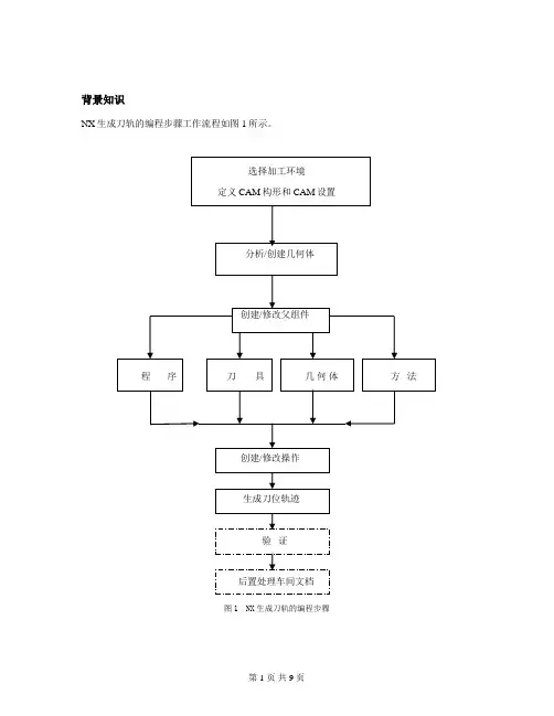
UG CAM试卷
- 格式:doc
- 大小:1008.30 KB
- 文档页数:22
UG CAM 操作试卷_答案
1 of 22
1. 打开文件planar_2.prt(图1-1)
图1 –1
a. 创建一把直径12mm的平底铣刀。
b. 创建一个面铣操作(FACE_MILLING_AREA),生成如图1-2和图1-3所示的刀具轨迹。
必须是单一操作。
分两层切削,每刀深度为10mm。
刀轨步距为刀具直径的百份之四十。
安全平面在工件上方50mm。
其余参数自订,但必须安全合理。
UG CAM 操作试卷_答案
2 of 22
2. 打开文件planar_1.prt。
a. 创建一铣刀,参数如图2-1所示。
b. 创建一平面铣操作,刀具轨迹如图2-2所示。加工参数自订,但必须安全合理。
图2-1
图2-2 UG CAM 操作试卷_答案
3 of 22 答案:
As long as the tool-path is correctly generated. UG CAM 操作试卷_答案
4 of 22
3. 打开文件Planar_4.prt。
编辑操作PLANAR_MILL:
a. 如下图所示,加0.15余量于其中一条边上(其余不变)。
b. 刀具在其中两条边上由tanto改为on。
c. 从外进刀。
图3
答案:
See planar_4_answer.prt
Edit the operation
Select “Part” boundary icon, then click “Edit” button.
The main boundary is highlighted, then click “Edit”, click > button until one of
the target member is highlighted, then change tool position from tanto to on.
Change another member, then click “OK”.
Click > button for another boundary, click “Edit”, directly select the target
member, then use customer member data to change stock value to 0.15.
Regenerate the tool-path.刀具在这两条边上由tanto改为on 从外进刀 0.15余量在这条边上 UG CAM 操作试卷_答案
5 of 22
4. 打开 P2.PRT 部件。
图4
绿色实体是零件;黄色是毛坯。使用已存刀具EM10创建型腔铣操作,要求如下:
a. 加工由毛坯顶至前方凹位平面。
b. 切削深度 (cut depth) 5mm。每层加工只提刀一次。
c. 侧壁余量和底余量同为1 mm。方形岛顶面、大平面及凹位平面皆为1 mm余量。
d. 圆形岛及方形岛都有均匀余量。
e. 刀具轨迹从外至内,并且从外进刀。
f. 其余参数自订,但必须安全合理。
答案: (see p2_answer.prt)
Select green solid as part geometry, yellow as blank geometry.
Set “Depth Per Cut” to 5
Define three cut ranges by picking three planar faces: square island top, big face
and bottom face of U shape area.
Set “Cut Method” to “Follow Periphery”
Cutting:
Inward
Island Cleanup
Use Floor Same As Side
Part Side Stock = 1 UG CAM 操作试卷_答案
6 of 22
5. 打开 P3.PRT部件,编辑操作TEST,生成刀具轨迹,使轮廓切削的起始点准确地从图5中所示的存在点开始;设置重复切削距离(Overlap Distance),使切削起始点和终止点为同一点。如下图5示。
图5
答案:
See following 2 pictures and p3_answer.prt
Control Points:
Cut region start points
Select the existing point
Automatic Engage Retract
Overlap Distance = 0 UG CAM 操作试卷_答案
7 of 22 UG CAM 操作试卷_答案
8 of 22
6. 打开 P4.PRT 部件, 编辑操作TEST,设置以下参数,然后生成刀具轨迹:如图 6所示.
a. 自动进刀方式为螺旋进刀(helical);
b. 增加拐角半径R1.5
c. 侧壁圆弧进刀半径R3.0
图6
答案:
See following two pictures and p4_answer.prt
Automatic Engage/Retract:
Ramp type: Helical
Arc Radius: 3
Corner:
Fillet: All Passes
Fillet Radius: 1.5 UG CAM 操作试卷_答案
9 of 22 UG CAM 操作试卷_答案
10 of 22
7. 打开 P6.PRT 部件,使用已存刀具D10R5创建 FIXED CONTOUR操作 ,产生以下图7所示刀具轨迹。参数自订,但必须安全合理。
图7
答案:
Surface Area drive method, without Part Geometry.
See p6_answer.prt UG CAM 操作试卷_答案
11 of 22
8. 打开 P8.PRT 部件,使用已存刀具D4R2创建FIXED CONTOUR 操作,产生如下图所示刀路。要求如下:
a. 两字雕刻由单一操作产生。
b. 雕刻深度1 mm,分三次加工(单一操作内)。
图8
答案:
Last drive curve of first character with “Local Lift at End” turned on.
Cutting: Part Stock = -1.0, Part Stock Offset = 1.0, Mutli-Depth Cut turned on,
Number of Passess = 3.
See p8_answer.prt UG CAM 操作试卷_答案
12 of 22
9. 打开 P12.PRT 部件文件,使用已存D10R5刀具创建 四个操作,产生如图9-1,9-2,9-3,9-4所示四个刀路。
a. 操作一,平行来回走刀方式,其它参数自订,但必须安全合理。
图9-1
b. 操作二,只加工操作一完成后比较粗糙的两侧陡峭部份。如下图所示。其它参数自订。
图9-2
c. 操作三,只加工非陡峭部份。加工参数自订。如下图所示。 UG CAM 操作试卷_答案
13 of 22
图9-3
d. 操作四,只加工操作三未能加工到的陡峭部份。加工参数可自订。如下图所示。
图9-4
答案:
see p12_answer.prt
Operation Operation Type Other settings
1 Surface Contouring
2 Surface Contouring Area Mill / directional steep
degree=60
3 Surface Contouring Area Mill / non-steep
Select 4 faces as cut area
Cutting – remove edge trace
4 Zlevel_profile_steep Cut area / steep angle