PLUS实时定位系统产品说明书
- 格式:pdf
- 大小:327.32 KB
- 文档页数:8
IPS User Manual V1.0室内定位系统用户手册、Content|目录Disclaimer|免责声明 (2)1.Introduction|介绍 (3)2.Basic Introduction|基础介绍 (4)2.1Hardware Preparation|硬件准备 (4)2.2Power Supply|供电 (4)3.IPS System Deployment|IPS系统部署 (5)3.1IPS Hardware Deployment|IPS系统硬件部署 (5)3.1.1Single Anchor Installation|单个基站安装 (5)3.1.2Two-dimensional Area Deployment|二维区域部署 (7)3.1.3One-dimensional Area Deployment|一维区域部署 (8)3.1.4Multiple Area Deployment|多区域部署 (8)3.1.5Attention|注意事项 (9)3.2IPS Software Deployment|IPS系统软件部署 (10)3.3IPS Software Configuration|IPS系统软件配置 (11)4.IPS System Operations|IPS系统操作 (17)4.1IPS Client Operation|IPS后台操作 (17)4.1.1Home|首页 (17)4.1.2Device Management|设备管理 (18)4.1.3Track Of History|历史轨迹 (18)4.1.4Alarm Management|告警管理 (19)4.1.5User Management|用户管理 (20)5.FAQ|常见问题解答 (21)6.Update Log|更新日志 (22)7.Further Information|更多信息 (23)Disclaimer|免责声明Document Information|文档信息Nooploop reserves the right to change product specifications without notice.As far as possible changes to functionality and specifications will be issued in product specific errata sheets or in new versions of this document.Customers are advised to check with Nooploop for the most recent updates on this product.Nooploop保留更改产品规格的权利,恕不另行通知。
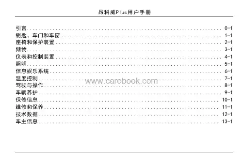
昂科威Plus用户手册引言....................................................................0-1钥匙、车门和车窗........................................................1-1座椅和保护装置..........................................................2-1储物....................................................................3-1仪表和控制装置..........................................................4-1照明....................................................................5-1信息娱乐系统............................................................6-1温度控制................................................................7-1驾驶与操作..............................................................8-1车辆养护................................................................9-1保修信息...............................................................10-1维修和保养.............................................................11-1技术数据...............................................................12-1车主信息...............................................................13-1引言0-1引言引言.....................................0-2引言..................................0-2使用手册............................0-2警告、告诫和注意................0-20-2引言引言引言本《用户手册》介绍了让您安全高效驾驶车辆所需的全部信息。
智能手持追踪器说明书首部欢迎使用智能手持追踪器!本说明书将为您详细介绍该产品的功能、操作指南以及注意事项。
在使用之前,请仔细阅读本手册,并按照指示正确操作。
祝您使用愉快!1. 产品概述智能手持追踪器是一款通过全球定位系统(GPS)和移动网络技术,用于追踪与定位物体或人员的便携设备。
该追踪器采用高精度芯片,能够精确定位目标,并通过手机应用程序实时展示定位信息。
2. 产品特点2.1 高精度定位:智能手持追踪器采用先进的GPS技术,能够提供高精度的定位信息,误差范围仅为数米,确保追踪目标的准确性。
2.2 移动追踪:用户可通过手机应用程序实时查看目标的位置,并能追踪目标的移动轨迹。
无论您身处何地,都能轻松实时监控目标的动态。
2.3 警报提醒:当目标离开设定范围、电池低电量或发生其他预设警报条件时,智能手持追踪器将自动发送提醒信息至用户手机,确保目标状态及时掌握。
3. 使用说明3.1 电池安装:打开追踪器背部的电池仓盖,按照正负极的标示,正确安装电池,并将电池仓盖牢固闭合。
3.2 产品激活:在首次使用之前,您需要下载并安装手机应用程序。
打开应用程序后,按照提示注册账号,并绑定智能手持追踪器。
激活成功后,您将能够开始使用该设备。
3.3 追踪目标设定:将您要追踪的目标物体或人员携带追踪器,并在应用程序中添加相应的目标设定。
您可以自定义目标的名称、备注等信息,以便更好地辨识和管理。
3.4 实时定位与追踪:打开应用程序,您将看到目标的实时定位信息。
可以通过地图查看目标所在位置,或者选择追踪模式,实时跟踪目标的移动轨迹。
3.5 警报设置:在应用程序中设置警报条件,如离开设定区域、电池低电量等。
当满足警报条件时,追踪器将向用户发送相应的提醒信息。
请根据实际需求进行设置。
4. 注意事项4.1 电池使用:请使用附带的电池,不得混用不同型号的电池。
在电池电量低于20%时,请及时更换新电池,以确保追踪器的正常运行。
4.2 数据使用:在使用移动网络数据时,请确保您已订购相应的流量套餐,以避免产生额外的费用。

NET20 PLUS GNSS连续运行参考站系统用户手册北京合众思壮科技股份有限公司说明产品标识版本说明目录说明 (2)第一章技术指标 (5)1.1欢迎使用NET20 PLUS (5)1.2技术规格 (5)1.2.1 物理特性 (5)1.2.2 环境特征 (5)1.2.3 电气特性 (5)1.2.4 性能 (5)1.2.5 接口 (6)1.2.6 数据与存储 (6)第二章 硬件组成 (7)2.1外观 (7)2.1.1 仪器正面 (7)2.1.2 仪器背面 (8)2.2连接及工作状态 (9)2.3结构尺寸图/安装尺寸图 (10)2.4启动主机 (10)第三章WEB应用 (12)3.1 WEB访问 (12)3.2系统状态 (13)3.2.1 系统信息 (13)3.2.2 GNSS状态 (13)3.2.3 卫星信息 (14)3.2.4 数据传输 (14)3.2.5数据记录 (15)3.3更改配置 (17)3.3.1 参考站设置 (18)3.3.2 网络设置 (19)3.3.3 数据传输设置 (22)3.3.4数据记录设置 (22)3.3.5 端口设置 (23)3.3.5.1 蓝牙 (23)3.3.5.2 COM1口方式 (26)3.3.5.3 SOCKET方式 (28)3.3.6 提醒设置 (30)3.3.7仪器注册 (31)3.4数据下载 (31)3.5系统管理 (32)3.5.1 在线升级 (32)3.5.2 日志查看 (33)3.5.3 安全管理 (35)3.6使用帮助 (35)第四章快速面板设置 (36)第一章技术指标1.1欢迎使用NET20 PLUS亲爱的用户,欢迎您使用北斗导航科技有限公司设计开发的NET20 PLUS GNSS连续运行参考站系统接收机。
NET20 PLUS是一款高性能CORS参考站接收机。
以LINUX系统作为开发平台,更支持二次开发,功能强大稳定,可以兼顾很多领域的不同应用。

PLUS实时定位系统 产品说明书北京奇立世通科技发展有限公司2010年1月1概述PLUS超宽频即时定位系统的由美国Time Domain公司出品。
和同类产品相比,该系统具有部署简单,性能价格比高,精度高,标签位置稳定不飘移,信号抗干扰能力强,标签发射状态和频率可以动态更新等突出特点。
系统由标签,阅读器,同步分配器,天线,标签确认点和定位软件组成。
标签是一个超宽频信号发射装置,每秒发射1~10次信号。
接收器(天线和阅读器的组合)接收标签发来的标签识别号,记录到达时间(TOA),然后传给同步器进行同步处理,解析出到达时间差(TDOA),然后把以上信号和其他一些验证信号例如信号强度等打包通过网络协议发送给服务器进行处理,就可以计算出标签(也就是需要被跟踪的人员或者物体)所处位置以及运动轨迹。
每一个标签都有一个独一无二的识别号,所以系统知道每一个标签在每一个时刻的位置以及运动信息。
标签确认点TAP向标签发射2.4 GHz 信号,可以动态地改变标签的发射频率(1~10Hz)和操作模式(活跃或者待机)。
这种设计可以使标签在非工作时间内处于待机状态,节省电池消耗,延长电池寿命。
PLUS系统部署符合本项目通过在固定场所布设定位接收装置,被定位人员佩戴射频信号发射标签的方式,实现指定区域内人员的实时精确定位并且被定位人员的坐标数据通过以太网实时传输给上层应用系统的要求。
标签位置偏差通常情况下不超过正负15cm,如果增加接收装置部署密度,精度更可达到正负5cm以下,超过建设要求。
如果部署在室外,标签的防护等级为IP64,满足建设要求。
信号中心频率为7.3GHz,带宽大约为1GHz,该频段为我国无线电管理开放频段,不会和现有通讯设备相互干扰,符合我国无线电管理规定。
系统遵循如下原则进行建设:(1) 先进性与成熟性原则:PLUS系统是著名实时射频定位系统生产商Time Domain的产品,在该领域享有盛誉,10多年来PLUS系统在美国的很多医院,养老院,超级市场部署,是先进成熟的产品。
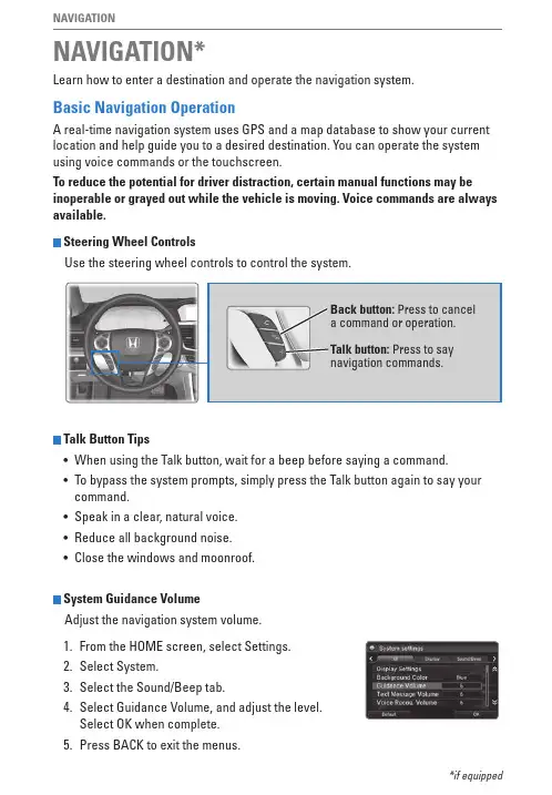
NAVIGATIONLearn how to enter a destination and operate the navigation system.Basic Navigation OperationA real-time navigation system uses GPS and a map database to show your current location and help guide you to a desired destination. You can operate the system using voice commands or the touchscreen.To reduce the potential for driver distraction, certain manual functions may be inoperable or grayed out while the vehicle is moving. Voice commands are always available.Steering Wheel ControlsUse the steering wheel controls to control the system.NAVIGATION**if equippedTalk Button Tips• When using the Talk button, wait for a beep before saying a command.• To bypass the system prompts, simply press the Talk button again to say your command.• Speak in a clear, natural voice.• Reduce all background noise.• Close the windows and moonroof.System Guidance VolumeAdjust the navigation system volume.1. From the HoMe screen, select Settings.2.Select System.3. Select the Sound/Beep tab.4. Select Guidance volume, and adjust the level. Select oK when complete.5. Press BACK to exit the menus.NAVIGATION Navigation Display and ControlsTouch icons on the screen to enter information and make selections.map screen.Navigation:the navigation screen.WARNINGUsing the navigation system while driving can take your attention away from the road, causing a crash in which you could be seriously injured or killed. operate system controls only when the conditions permit you to safely do so.NAVIGATIONEntering a DestinationUse several methods to enter a destination.Home AddressStore your home address in the system so you can easily route to it.1. From the map screen, select the Search icon.2. Select MeNU.3. Select Set Home Location.4. Select enter My Address.5. Select Search All.6. Enter the street number and select Done.7. enter the street name and select Done. Selectthe street from the list.8. Select the address from the list. A map of theaddress is shown. Select Select.When your home address is stored, you can press the Talk button and say “Navigation” and then “Go home” at any time. You can also select Go Home from the Where To? menu.Street Addressenter a street address.1. From the map screen, select the Search icon.2. Select Address.3. Select Search All.4. Enter the street number and select Done.5. enter the street name and select Done. Selectthe street from the list.6. Select the address from the list.7. Select Go!.You can also enter a street address using voicecommands. Press the Talk button and say “Navigation” and then “Find Address.” Follow theprompts.NAVIGATION Place Categoryenter a destination using a point of interest or landmark.1.From the map screen, press MeNU.2.Select Where To?.3.Select Categories.4.Select a category (and a subcategory if necessary).5.Select a place from the list.6.Select Go!.You can also enter a street address using voicecommands. Press the Talk button and say “Navigation” and then “Find Place.” Follow theprompts.Recent PlacesSelect an address from a list of your 50 most recent destinations.1.From the map screen, press MeNU.2.Select Where To?.3.Select recent.4.Select a place from the list.5.Select Go!.NAVIGATIONSaved PlacesSave locations so you can quickly route to them.Saving a location1. From the map screen, press MeNU.2. Select Where To?.3. Select enter Search.4. enter the address or place name.5. Select the destination name when it appears onthe map screen.6. Select the menu icon.7. Select Save.8. Select oK.You can also save your current location. From the map screen, select the vehicle icon. Select Save. enter a name for the location. Select Done. Select oK. Routing to a saved location1. From the map screen, press MeNU.2. Select Where To?.3. Select Saved.4. Select the destination from the list.5. Select Go!.NAVIGATION RoutingAfter a destination is set, you can alter or cancel your route.Map LegendShows a more detailed view of the next maneuver on the upper display.NAVIGATIONTrafficview traffic flow and incidents in major metro areas. You can also select traffic to avoid. Traffic coverage is limited in Canada.Viewing traffic1. From the map screen, select the traffic icon.2. Select Traffic Conditions.3. Traffic icons are shown on the map. Select themagnifying glass icon to display a full list oftraffic delays.Avoiding traffic on your route1. From the map screen, select the traffic icon.2. Select Traffic on route.3. Select an incident to avoid from the list.4. Select the menu icon.5. Select Avoid.。
深圳市聚鼎诚科技有限公司GPS 定位终端 GPS 定位软件 GPS 定位系统服务 GPS定位系统建设规划和信息咨询关于我们深圳市聚鼎诚科技有限公司专业从事GPS远程定位产品开发,设计和制造。
我们的产品和系统广泛应用到需要定位的行业和领域当中:从物流车,到特种车辆;从私家车防盗,到租赁车抵押;从公司规划车辆路线,到出差人员管理,我们的产品正在给客户带来安全和保障,提高效率和效益,帮助用户创造新的价值。
主要产品和服务如下:GPS定位终端在定位系统中,定位终端也称之为硬件产品,为整个系统之基础。
其规格,性能与参数直接决定产品的功能应用范围及精度等等。
GPS定位软件GPS车辆定位系统管理软件可以满足不同用户需求,从个人消费者,到大中型企业;从几十台中小规模车队,到几千辆车大型行业公司,我们都有与之对应的方案和软件。
GPS定位系统服务我们提供远程网络定位服务方便客户来体验硬件设备和软件。
同时客户可以将其设备连接到我们的服务器上运转,从而避免了架设服务器的环节和费用。
GPS定位系统建设规划和信息咨询我们提供免费技术咨询和系统建设规划。
我们可以协同您一起量身定做贵司的GPS定位方案。
目前,我的产品和系统服务不仅在国内销售,还远销到美国,加拿大,西班牙,葡萄牙,南非,秘鲁,巴西,等十几个国家和地区。
并且随着GPS产品应用普及,涉及领域增加,越来越多的经销商从各地参与到共同的事业中。
技术和产品为我们赢得各地客户,而服务和信誉更使客户成为长期合作伙伴。
“我们不是在寻找商人做生意,而是寻找合作伙伴共同成长”,这是我们一贯的经营理念。
本手册是为用户提供硬件产品参考信息,包括硬件的功能,参数和使用方式。
您如果想了解更多的信息,请登陆我们的网站或直接和我们联系。
深圳聚鼎诚科技有限公司GPS定位监控产品研制应用地址:广东深圳宝安区西乡大道华源商务中心416电话**************传真**************邮政编码:518102电子邮件:********************产品一览在定位系统当中,定位终端是整个系统的基础。
SUMMIT系统用户手册------------轻便、灵活的地震数据采集系统………………………Summit II plus系统Summit II plus系统是早期的Summit系统的新一代产品,两种系统相互间是完全兼容的。
SummitII plus系统由下面单元构成:USB接口数据采集单元RU中继单元RP触发单元TU电缆手持袖珍定位仪USB接口通过USB连接线将主机(笔记本电脑)和地震排列连接起来。
由于采用了即插即用的USB技术,所以可以在任何时候把USB接口与地震排列连接或断开。
此外,USB接口可以连接到地震排列的任何位置上。
●在USB接口的上面有一个电源/数据线接口(母的)和三个状态指示灯●在USB接口的前面有四个BNC插口用于触发信号的输出或输入。
●在USB接口的后面有一个电源/数据线接口(公的),一个USB通讯接口及一个外部供电电源接口。
下面将加以详细描述:USB接口上面USB接口前面USB接口下面上面在USB接口的上面有一个电源/数据线接口(母的)和三个状态指示灯:注意:在仪器软件升级时,所有的三个指示灯都亮。
在升级完成后,三个指示灯都闪烁。
前面板在USB接口的前面有4个与触发相关的BNC插头:后面板USB接口的后面板有一个电源/数据线接口(公的),一个USB通讯接口和外接电源插头。
数据采集单元(RU)是应用24位α-γ技术的A/D转换器的两道地震数据采集单元。
所有的数据采集单元(RU)均通过USB接口由笔记本电脑(中央单元)控制和监视。
数据和控制指令完全是数字信号传送。
必须应用外部电池给数据采集单元(RU)供电。
所有数据采集单元(RU)的器件都内置于牢固的金属外壳内,以保证其最大的稳定性和抗雷电能力。
每一个数据采集单元(RU)有一个唯一的物理地址编号(在标签上),内含2块电路板:分别叫做SPM(信号处理模块)和BMP(蓝牙电源模块)。
SPM负责采集数据的前置放大,滤波,数字化,叠加,相关和储存。
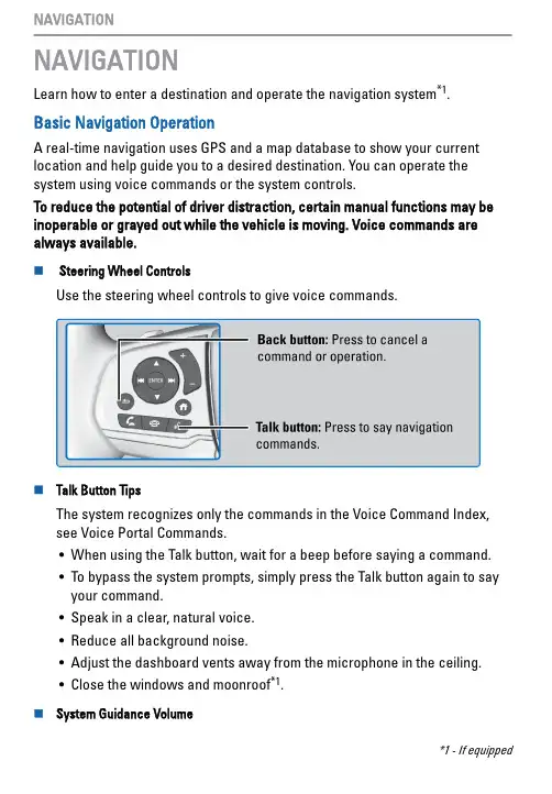
NAVIGATIONLearn how to enter a destination and operate the navigation system*1.Basic Navigation OperationA real-time navigation uses GPS and a map database to show your current location and help guide you to a desired destination. You can operate the system using voice commands or the system controls.To reduce the potential of driver distraction, certain manual functions may be inoperable or grayed out while the vehicle is moving. Voice commands are always available.n Steering Wheel ControlsUse the steering wheel controls to give voice commands.n Talk Button TipsThe system recognizes only the commands in the Voice Command Index, see Voice Portal Commands.•When using the Talk button, wait for a beep before saying a command.•To bypass the system prompts, simply press the Talk button again to sayyour command.•Speak in a clear, natural voice.•Reduce all background noise.•Adjust the dashboard vents away from the microphone in the ceiling.•Close the windows and moonroof*1.n System Guidance Volume*1 - If equipped1.From the Home Screen, selectNavigation.2.Select Map Tools, Then Guidancevolume.3.Select + or - to adjust volume, orselect Mute.4.Press Back to exit the menus.n Navigation Display and ControlsTouch icons on the screen to enter information and make selections.Entering Your DestinationUse several methods to enter a destination.n Home AddressStore your home address in the system so you can easily route to it.1.Select Set Home Location.2.Select an option.Select Use Current Location to sethome location.If selecting Enter My Address,Recently Found or Saved Place,proceed to steps 3 and 4.3.Select the home location.4.Select Select.When your home address is stored, you can press the Talk button and say "Navigation" and then "Go Home" at any time. You can also select Go home from the Where To? menu.n Street AddressEnter a street address.1.From the map screen, select theSearch icon.2.Select Search Tools.3.Select Address.4.Enter the house number and streetname.5.Select Done or a suggestion.6.Select the address from the list.7.Select Go!.n Place CategoryEnter a destination using a point of interest or landmark.1.From the map screen, select theSearch icon.2.Select a Category.3.Select a subcategory.4.Select a place from the list.5.Select Go!.You can also enter a street addressusing voice commands. Press the Talkbutton and say “Navigation” and then“Find Place.” Follow the prompts.n Recent PlacesSelect an address from a list of your 50 most recent destinations.1.From the map screen, select theSearch icon.2.Select Recent.3.Select a place from the list.4.Select Go!.n Saved PlacesSave locations so you can quickly route to them.Saving a Location1.Select a destination from the map.2.Select the destination name at thebottom of the map.3.Select Save.4.Enter the address or place nameans select done.Routing to a Saved Location1.Select a search method.Find a location that you want tosave.2.Select Info.3.Select Save.4.Enter a name and select Done.RoutingAfter a destination is set, you can alter or cancel your route.n Map LegendUsing the navigation system while driving can take your attention away from the road, causing a crash in which you could be seriously injured or。
GPS 系统使用说明书Gps手机定位系统客户端软件说明一、启动程序点击GPS手机定位程序启动。
二、用户登录直接输入用户名、密码,点击确定。
您便成功登陆至GPS手机定位系统客户端软件。
三、界面介绍在地图窗口点右键,出现清除鼠标状态、放大当前地图、缩小当前地图、漫游当前地图、地图区域设置、刷新地图屏幕、,目标线路导航、目标实时跟踪、清除实时跟踪功能。
四、工具栏介绍1 2 3 4 5 6 7 8 9 10 11 12 13 14 15 16 17 18 19 20 21 22 23 24 25 261、窗口管理:您可以在地图显示窗口中增加地图窗口。
点击增加窗口管理按钮后,地图显示窗口中就会出现一个新的监控窗口,最多可显示四个窗口。
2、删除窗口管理:您可以在地图显示窗口中删除地图窗口。
点击删除窗口管理按钮后,就可以删除一个监控窗口,至少会有一个窗口留下。
3、还原鼠标状态:将状态转换为可操作的鼠标状态。
4、放大地图:放大地图的比例。
5、缩小地图:缩小地图的比例。
6、地图漫游:平移地图。
7、测量距离:选择此键在界面的左下角显示您测的两点距离。
8、拷贝地图:可以将当前地图窗口显示的地图(按照您的要求填写对话框)拷贝转为地图文件。
9、地图还原:将现在所显示的地图画面转为初始状态下的地图窗口。
10、查看指定范围目标:选择此键在界面中会弹出所选范围的终端列表框。
11、设定圆形报警区域:选择此键后可在地图中设定您所需要的圆形报警范围。
12、设定特定报警区域:选择此键后可在地图中设定您所需要的任意形状报警范围。
(点击鼠标右键确认设置)13、目标导航:选择此键后可在地图中绘制您需要的路线,之后找到您要发送导航信息的ID号,点击鼠标右键发送此信息。
如要取消导航信息则点击键盘中的“DEL”键。
14、离线终端列表:显示超过规定时间GPS点位没有更新的终端。
15、选取图元:只可选取自定义的图元(及信息符号),不能选原图中的图元。
UWB ProTag2s使用手册Version 1.2研创物联 UWB ProTag2s 使用手册V1.2© 温州市研创物联网科技有限公司2015-2019Page 2目录研创物联定位开发套件简介....................... 3 研创UWB 系列及其套件 .................................... 3 研创物联UWB 系列模块详细参数对比 ............ 3 模块概述 .............................................................. 4 应用场合 .............................................................. 4 国内外室内定位技术的优缺点 .. (4)专业术语表 (5)主要参数 .................................................... 6 出厂程序固件 ...................................................... 6 硬件参数 .............................................................. 6 硬件IO 分配一览 ................................................ 6 实测频谱 .. (6)硬件接口定义 (7)常见技术问题问答 ..................................... 8 原理. (8)使用 (8)UWB 定位套件测试说明 ............................ 9 模式配置 .............................................................. 9 定位测试:3基站+1标签测试 .. (9)测距测试:1基站+3标签测试 (11)研创定位系统数据入网解决方案简介 (12)概述 (12)UWB 模块二次开发 .................................. 13 开发环境和工具 ................................................ 13 固件更新 (13)从USB 虚拟串口输出数据的方法 (13)PC 上位机通讯数据格式与二次开发 ........ 15 实时定位系统上位机简介 ................................ 15 实时定位系统上位机界面 ................................ 15 数据帧TOF Report Message .............................. 17 日志文件Log Files (18)三边定位法Trilateration 的原理与计算方法 (18)UWB 产品化开发 ..................................... 20 数据标定方法 .................................................... 20 进一步提升测距刷新速率的方法 .................... 20 进一步提升定位刷新速率的方法 .. (21)遮挡对室内定位UWB 的影响 (21)AT 指令集 ................................................. 22 AT+QSET 指令 ......................................................... 22 订购信息 .................................................. 23 联系方式 (23)对公转账信息 (23)文档管理信息表 (24)研创物联定位开发套件简介研创UWB系列及其套件项目简介提供的资料内容UWB Mini3 开发板模块采用STM32F105RCT6单片机为主控芯片。
3DM GQ7-GNSS/INS Complete RTK Navigation SystemSystem architecture3DM GQ7-GNSS/INSThe 3DM GQ7-GNSS/INS is an all-in-one navigation solution featuring centimeter-level position accuracy. It is equipped with dual multiband GNSS receivers, low noise and low driftMEMS inertial sensors, and a robust adaptive Kalman filter.System featuresDual antenna GNSSCentimeter-level accuracy with RTK Tactical Grade IMUAdvanced tightly-coupled extended Kalman filter (EKF) for sensor fusionLow profile and lightweight at 78 grams Adjustable sampling rates up to 1 KHz <2 deg/hour gyro bias instability3DMGQ7 performancePositionSingle point, horizontal [1] 1.25 m Single point, vertical [1]2 m RTK [1,2]2 cm[1] 24 hour static, RMS[2] 1cm + 1ppm, 2cm at 10km from the base stationAttitude Roll, Pitch .05°Heading [1].25°[1] Dual antenna requiredDynamic Velocity0.05 m/sSensorCloud RTK provides seamless cloud-based network RTK corrections without the need for customer-supplied base stations, and includes a cellular data plan and network RTK coverage.The encrypted data stream secures position data and keeps it ers can get started instantly with this commitment-free subscription service, available immediately after registration.3DMRTKCellular RTK correction modemThe3DM RTK provides easy to use real time Kinematic (RTK)correction data to be utilized by the 3DM GQ7-GNSS/INS. It provides the simplicity of a cellular connection to our SensorCloud RTK base station network, replacing traditional radio-based stations. With RTK corrections the 3DM GQ7 can achieve centimeter-level positional accuracy. By removing the need for base station infrastructure the 3DM RTK minimizes the user’s required time to market.MicroStrain offers an open source, license-free (MIT License) series of drivers specifically designed and SensorConnect is PC software for sensor configuration and data collection. Configure inertial parameters, device settings, data channels, and sample rates. Visualize massive amounts of data instantly using built-in intelligent data collection and graphing algorithms. Create immersive dashboards with rich data visualization.MSCL™ & APIsThe MicroStrain Communication Library simplifies writing code to interact with our sensors. MSCL isour open-sourced API, readily available and fully-documented on GitHub, featuring valuable tools such as full documentation, example code, and a quick start guide.Byte-level data communication protocols are available in the DCP section of our user manual.3DM GQ7 SpecificationsIMUAccelerometer GyroscopeRange±8g±300°/sRandom walk20 μg/√Hz8.75°/s/√HzBias instability0.05 mg 1.5°/hInterfaceConnectors 2 x Micro-D9Communications interface 2 x RS-232, 2 x USBGNSS antenna ports 2 x MMCXData output rate 1 to 1000 HzExternal aiding input RTCM 3.1, GNSS, odometer, headingI/O 4 x GPIOGPIO Functions Odometer, event triggering, PPS input/outputGNSSNumber of receivers2Channel count184Constellations GPS/QZSS , GLONASS, Galileo, BeiDou*Frequencies L1C/A, L2C, L1OF, L2OF, E1B/C, E5b, B1, B2 Operational Limits Altitude 50,000 meters | Velocity 500 m/s*BeiDou RTK support to be provided in a future firmware release.Physical and ElectricalWeight78gSize76 mm x 68.6 mm x 13.3 mmPower Consumption 2.0W (typical), 2.5W (max)Operating voltage 5 to 16 VDCGPIO Voltage5VOperating Temperature-40° to 85°CAntenna output voltage3VAntenna output current100mAMTBF389,237 hours (Telcordia method, GM/35C)3DM RTK SpecificationsData output rate 1 HzInterface Micro-D9, RS 232, USBProtocols MIP, RTCM 3.1, NMEACellular Network Cellular Coverage: Global*Voltage 5 to 16 VDCPower 1.0W (typical), 2.0W (max)Weight48g*Some regional restrictions apply. Coverage only where LTE CAT-M1/2G deployment is available. Please see our RTK webpage for details.application videoApplications©2020 Parker Hannifin MicroStrain Sensing. | Document 8400-0139 Revision -. | Subject to change without notice.Parker Hannifin Corporation MicroStrain Sensing 459 Hurricane LaneWilliston, VT 05495 • USAphone: +1.802.862.6629email:********************************************** 。
Enduro Plus 3GMulti-purpose Tracking DeviceUSER MANUALa c k i n g T h e W o r l d.c o mGeneral NotesTrackingTheWorld offers this information as a service to its customers, to support application and engineering efforts that use the products designed by TrackingTheWorld. The information provided is based upon requirements specifically provided to TrackingTheWorld by the customers. TrackingTheWorld has not undertaken any independent search for additional relevant information, including any information that may be in the customer’s possession. Furthermore, system validation of this product designed by TrackingTheWorld within a larger electronic system remains the responsibility of the customer or the customer’s system integrator. All specifications supplied herein are subject to change.CopyrightThis document contains proprietary technical information which is the property of TrackingTheWorld, copying of this document and giving it to others and the using or communication of the contents thereof, are forbidden without express authority. Offenders are liable to the payment of damages. All rights reserved in the event of grant of a patent or the registration of a utility model or design. All specification supplied herein are subject to change without notice at any time.Copyright © TrackingTheWorld 2016For More Information: Please contact TrackingTheWorld, 1633 Bayshore Highway, Suite 390, Burlingame, CA. 94010, USA Phone: +1.650.692.8100 – Email: *************************– Website: ContentsContents (3)0. Revision history (4)1. Introduction (5)2. Product Overview (6)2.1. Appearance (6)2.2. Buttons/Mini USB Interface Description (6)2.3. LEDs Description (7)2.4. External Power Interface (7)2.4.1. External DC Charger Interface (7)2.4.2. External Battery Interface (8)2.5. Ignition Detection (8)2.6. External Input Interface (9)3. Getting Started (10)3.1. Parts List (10)3.2. Battery Charging (10)3.3. ENDURO PLUS 3G External Cable Interface (11)3.4. Turn on/Turn off (11)4. Troubleshooting and Safety info (12)4.1. Troubleshooting (12)4.2. Safety info (12)For More Information: Please contact TrackingTheWorld, 1633 Bayshore Highway, Suite 390, Burlingame, CA. 94010, USA Phone: +1.650.692.8100 – Email: *************************– Website: 0.Revision historyFor More Information: Please contact TrackingTheWorld, 1633 Bayshore Highway, Suite 390, Burlingame, CA. 94010, USA Phone: +1.650.692.8100 – Email: *************************– Website: 1.IntroductionThe water resistant ENDURO PLUS 3G is a powerful GPS locator designed for lone worker, vehicle, pet and asset tracking applications. The thumb sized button makes this device ideal for applications requiring rapid notification of emergency alert or regular setting of geo-fences based on current location. Its built-in GPS receiver has superior sensitivity and fast time to first fix. Its UMTS allows the ENDURO PLUS 3G's location to be monitored in real time or periodically tracked by a backend server and mobile devices. Its built-in 3-axis accelerometer allows motion detection and extends battery life through sophisticated power management algorithms. System integration is straightforward as*******************************************************************@Trackprotocol supports a wide variety of reports including emergency, geo-fence boundary crossings, low battery and scheduled GPS position.For More Information: Please contact TrackingTheWorld, 1633 Bayshore Highway, Suite 390, Burlingame, CA. 94010, USA Phone: +1.650.692.8100 – Email: *************************– Website: Copyright © TrackingTheWorld. All rights reserved. Information in this publication supersedes that in all previously published material. Specification and price2.Product Overview2.1.Appearance2.2.Buttons/Mini USB Interface DescriptionFor More Information: Please contact TrackingTheWorld, 1633 Bayshore Highway, Suite 390, Burlingame, CA. 94010, USA Phone: +1.650.692.8100 – Email: *************************– Website: Copyright © TrackingTheWorld. All rights reserved. Information in this publication supersedes that in all previously published material. Specification and price2.3.LEDs DescriptionThere are three LED in ENDURO PLUS 3G, their description are as follow:2.4. External Power Interface2.4.1.External DC Charger InterfaceThe Pin2 on Mini-USB connector are used for charging and named as VCHG pin, It can be connected to a 5V DC power supply to power ENDURO PLUS 3G and charge the internal battery.For More Information: Please contact TrackingTheWorld, 1633 Bayshore Highway, Suite 390, Burlingame, CA. 94010, USA Phone: +1.650.692.8100 – Email: *************************– Website: Copyright © TrackingTheWorld. All rights reserved. Information in this publication supersedes that in all previously published material. Specification and priceThe Pin 8 on Mini-USB connector is for external battery and named as EXTBAT pin, It can be connected to 3.7V Li-ion or Li-Polymer battery to power ENDURO PLUS 3G.2.5. Ignition DetectionThe Pin 7 on Mini-USB connector is for ignition detection when ENDURO PLUS 3G is used in vehicle tracking application, It is named as IGN_IND pin.Another easy way is to connect PIN7 to a power output in the fuse box of the vehicle which is only enabled after the vehicle is ignition on. For example: the power output for radio FM.For More Information: Please contact TrackingTheWorld, 1633 Bayshore Highway, Suite 390, Burlingame, CA. 94010, USA Phone: +1.650.692.8100 – Email: *************************– Website: Copyright © TrackingTheWorld. All rights reserved. Information in this publication supersedes that in all previously published material. Specification and priceThe Pin 5 on Mini-USB connector is a negative trigger input in newer hardware version. It is named NSW pin. For negative trigger input the electrical conditions are:An input example is shown as following figures:Example of NSW pin connect to a panic buttonFor More Information: Please contact TrackingTheWorld, 1633 Bayshore Highway, Suite 390, Burlingame, CA. 94010, USA Phone: +1.650.692.8100 – Email: *************************– Website: Copyright © TrackingTheWorld. All rights reserved. Information in this publication supersedes that in all previously published material. Specification and price3.Getting Started3.1.Parts ListTheWCDMA/GPRS/GSM/GNSS/GPSlocator.It is used to charge the internalbattery of ENDURO PLUS 3G.It is the USB data cable which canbe used for firmware upgradingand configuration.It is the extend cable whichinclude the charger interface andexternal battery interface onENDURO PLUS 3G. It also includesthe ignition detection interface onthe ENDURO PLUS 3G.●Please connect AC-DC power adapter with ENDURO PLUS 3G.●Insert the AC-DC power adapter into the power socket.●During charging, the PWR LED is flashing fast. When the battery is full charged, the PWR LED will beEver-light.●You can also charge the battery by USB cable which connects ENDURO PLUS 3G with the PC.●Charging time is about 5 hours.Note: Before the first time using ENDURO PLUS 3G, please full charge the battery.For More Information: Please contact TrackingTheWorld, 1633 Bayshore Highway, Suite 390, Burlingame, CA. 94010, USA Phone: +1.650.692.8100 – Email: *************************– Website: Copyright © TrackingTheWorld. All rights reserved. Information in this publication supersedes that in all previously published material. Specification and price3.3.ENDURO PLUS 3G External Cable Interface●ENDURO PLUS 3G External Cable is a cable with a Mini USB connector and six wires which includethe external power interface, ignition detect and input interface for ENDURO PLUS 3G. Please find the detail description in following table.●Turn on:◆Method 1: Press the Power key at least 3 seconds and release it to turn on ENDURO PLUS 3G. Atthe same time, PWR LED will light on.◆Method 2: Connect device to charger or external battery, and it will turn on automatically, PWRLED will light on.●Turn off:◆Method 1: Press the power key about 2 seconds; PWR LED will fast flash and then turn off, itindicates that ENDURO PLUS 3G is turned off. The time of power off is depended on the quality of network. The maximum time of power off is 90 seconds. It is only valid to turn off when using internal battery. Please note the end-user cannot power off ENDURO PLUS 3G when the power key is disabled by protocol.Method 2: If using external battery, device power will turn-off when external battery disconnect.For More Information: Please contact TrackingTheWorld, 1633 Bayshore Highway, Suite 390, Burlingame, CA. 94010, USA Phone: +1.650.692.8100 – Email: *************************– Website: Copyright © TrackingTheWorld. All rights reserved. Information in this publication supersedes that in all previously published material. Specification and price4.Troubleshooting and Safety info4.1.Troubleshooting●Please do not disassemble the device by yourself.●Please do not put the device on the overheating or too humid place, avoid exposure to directsunlight. Too high temperature will damage the device or even cause the battery explosion.●Please do not use ENDURO PLUS 3G on the airplane or near medical equipment.For More Information: Please contact TrackingTheWorld, 1633 Bayshore Highway, Suite 390, Burlingame, CA. 94010, USA Phone: +1.650.692.8100 – Email: *************************– Website: Copyright © TrackingTheWorld. All rights reserved. Information in this publication supersedes that in all previously published material. Specification and price。
SmartLBS智能定位平台操作说明长春位智天下技术有限公司目录一、位智天下定位平台 (3)1 登录平台 (3)2 平台主界面综述 (4)3 平台模块介绍 (5)1.3.1平台即时定位功能模块 (5)1.3.2 轨迹查询 (7)1.3.3 考勤报表功能模块 (8)1.3.4 位博功能模块 (11)二、定位平台后台管理 (13)1 平台后台管理 (13)2 平台后台管理操作 (13)2.2.1 平台信息 (13)2.2.1.1 操作记录 (13)2.2.2 公司管理 (14)2.2.2.1 公司信息 (14)2.2.2.2 部门信息 (15)2.2.3 人员管理 (17)2.2.3.1 员工信息 (17)2.2.3.2 终端管理 (20)2.2.3.3 拜访历程统计 (21)三、平台常见问题及解析 (24)注:该说明中显示模糊部分的是受保护的企业信息,并非平台显示问题。
一、位智天下定位平台1、登陆平台此为位智天下定位平台首页(/)输入用户名、密码登录平台。
图为位智天下定位平台主界面:2、平台主界面综述如图标记所示标记1为功能选项卡,负责功能模块的切换标记2为人员选择区,负责定位人员的点选标记3为功能点选按钮,选择人员后选取该功能的按钮确定系统的功能展示方式标记4为登陆者信息和其所跳转的其他功能。
其中点选首页则保留系统登陆状态,页面跳转回首页;点选管理后台则系统跳转该登陆者权限所应允的后台管理系统;点选个人计划则进入个人计划功能模块,详见个人计划模块点选客户端下载则自动下载该登陆人员对应的客户端点选退出,则注销用户的登陆状态,返回主页标记5为地图。
用于展示定位人员的地理位置信息记6为地图模式切换操作,您可以操作地图显示方式3、平台模块介绍1.3.1平台即时定位功能模块点击即时定位选项卡,在人员选择区将您想选择的定位人员勾选,点击功能选项按钮,或者直接点击您想定位人员的姓名超链接,您就可以在地图展示区看到您的定位人员详细状况。
Specifications are subject to change without notice.- 1 -First issue: Apr. 1998Rev.10: Nov. 2002Smart Valve PositionerModels AVP300 and AVP301OVERVIEWSVP3000 Alphaplus models A VP300 andA VP301 are current-pneumatic smart valve posi-tioners.The SVP3000 Alphaplus receives a DC current signal from control devices and controls pneu-matic valves. In addition to this basic function, the SVP3000 Alphaplus has communication capabilities, automatic configuration program, and self diagnostics functions that will greatly increase productivity and the efficiency of plant operation.The model A VP301 has a valve travel transmit-ter function which transmits a 4-20mA DC sig-nal.FEATURESEasy to use•Auto setupThe auto-setup function is a fully-automatic con-figuration program which specifies the actuator and adjusts the zero and span of the valve. The program can be turned on simply from an exter-nal switch so that adjustments to the valve can be performed quickly and safely in hazardous areas.High reliability•Positive seatingThe positive seating function completely shuts off the valve if the input signal becomes lower than previously set. This in turn enhances the full shut-off capabilities of the valves.•Self-diagnosticThe self-diagnostic function provides with the ability to check the status of the positioner at any time and to alert in case of failure.Single model for multiple specifications SVP Alphaplus' settings can be changed without replacing any parts. A single model can be mod-ified to suit any application.•Input range : Configurable to any required range for split range•Flow characteristic : Linear, EQ%, Quick opening or custom user characteristics • Actuator type : Singl e or double acting actua-tor (optional reversing relay required)Travel transmissionThe model A VP301 transmits a 4-20mA signal proportional to the valve travel. The valve travel can be monitored from the control room.No. SS2-AVP300-0100 (Rev.10)Yamatake Corporation- 2 -FUNCTIONAL SPECIFICATIONSApplicable actuatorSingle and double acting actuator Linear and rotary motion actuatorApprovalsJIS Flameproof approvalEx d IIC T6 X Approval No. C13270FM Explosionproof approvalExplosionproof for Class I, Division 1, Group A, B, C, DDust-ignition for Class II, Division 1, Group E, F, G Suitable for Class III, Division 1Flameproof for Class I, Zone 1, AEx d IIC T6 at Ambient temperature<80°C Approval no. 3001246Installation should comply with NEC.FM Intrinsically safe approvalIntrinsically safe for Class I, II, III, Division 1, Group A, B, C, D, E, F, G, T4Intrinsically safe for Class I, Zone 0, AEx ia IIC T4Nonincendive for Class I, Division 2, Group A, B, C, D, T5Suitable for Class II, III, Division 2, Group F, G, T4Approval No. 3006126The barriers should be FM recognized types and comply with the following conditions as follows.Input signal line:12.02≤Vmax ≤30V , Imax=100mA,Pmax=1W, Ci=0.0uF, Li=0.22mHFor travel transmission line: Vmax=30V ,Imax=100mA, Pmax=1W, Ci=0.07uF, Li=0.22mHInstallation should comply with NEC.ISSeP/CENELEC Flameproof approvalEEx d IIC T6, IEC IP66Flameproof cable gland and stopping plug should be an approved model of EEx d IIC. Cable gland must be equivalent to IP66 standard.CSA Explosionproof approvalExplosionproof for Class I, Division 1, Group B, C, and DFlameproof for Class I, zone 1, Ex d IIC, T6Dust ignition proof for Class II and III Division 1, Group E, F and G Type 4X, Approval No. 188352-2500004029, LR113752-6KEMA/CENELEC Intrinsically safe approvalIntrinsic safety:II 1 G EEx ia IIC T4Dust ignition protection:II 1 D T135 °C Approval No. KEMA 00ATEX1111 XThe barriers should be CENELEC certified types and comply with the following condition as follows.•Model A VP300:Input circuit (terminals ±IN )Ui=30V , li=100mA (resistively limited), Pi=1W, Ci=1nF, Li=0.2mHOutput circuit (terminals ±OUT )Ui=30V , li=100mA (resistively limited), Pi=1W, Ci=1nF, Li=0.3mHBoth circuits shall be considered to be connected to ground from a safety point of view.•Model A VP301:Input circuit (terminals ±IN )Ui=30V , li=100mA (resistively limited), Pi=1W, Ci=1nF, Li=0.2mHOutput circuit (terminals ±OUT )Ui=30V , li=100mA (resistively limited), Pi=1W, Ci=1nF, Li=0.2mHBoth circuits shall be considered to be connected to ground from a safety point of view.NEPSI Flameproof approvalEx d IIC T6 (except acetylene), with NEPSI Dust igni-tion DIP DT T13Approval No. GYJ99101Flameproof cable gland must be an approved model of NEPSI Ex d IIC.NEPSI Intrinsically safe approvalEx ia IIC T4-T6 (with NEPSI Dust Ignition DIP DT T13Approval No. GYJ99104It must be used with the following Zener barrier which is approved by NEPSI.A VP300:Two pieces of each MTL728, Z728 or LB928A VP301:For input signal; Two pieces of each MTL728,Z728 or LB928For travel transmission: MTL787S, Z787 or LB987S Capacitance of wiring should be lower than 0.06uF.Inductance of wiring should be lower than 1mH. A cable gland which is NEPSI recognized is recommended.Combination of NEPSI Flameproof and Intrinsically safeWhen used as NEPSI Flameproof, it complies NEPSI Flameproof approval as above,When used as NEPSI Intrinsically safe, it complies NEPSI Intrinsically safe approval as above.Control signal input4-20mA DC (Configurable any required range for split range.)Input resistance300 Ω max / 20mA DCOutput characteristics•Linear, Equal percentage, Quick opening •Custom Configurable- 15 segmentsStem travel rangeFeedback Lever Angle ± 4° to ± 20°Bypass operationAuto/Manual external switch (For single acting type only)Air supply pressure140 to 700 kPa (1.4 to 7.0 kgf/cm 2)Yamatake Corporation No. SS2-AVP300-0100 (Rev.10)- 3 -Air consumption4 l /min(N) maximum at 140 kPa (1.4 kgf/cm 2)5 l /min(N) maximum at 280 kPa (2.8 kgf/cm 2)6 l /min(N) maximum at 500 kPa (5.0 kgf/cm 2)10 l /min(N) maximum at 400k Pa (4.0 kgf/cm 2) for dou-ble acting typeMaximum air deliver flowrate110 l /min(N) at 140 kPa (1.4 kgf/cm 2)250 l /min(N) at 400 kPa (4.0 kgf/cm 2) for double acting typeOutput balanced pressure55 ± 5% for double acting type onlyLightning protectionPeak value of voltage surge: 12 kV Peak value of current surge: 1000 AVibration tolerance2G (5 to 400 Hz)(with standard mounting kit on Yamatake HA actuator)Ambient temperature limits-40°C to 80°C for general model JIS Flameproof model :-20°C to 60°C FM Explosionproof :-40°C to 80°C FM Intrinsically safe :-40°C to 80°C ISSeP/CENELEC Flameproof :-20°C to 70°C CSA Explosionproof :-40°C to 80°C KEMA/CENELEC Intrinsically safe: -40°C to 60°C NEPSI Flameproof :-40°C to 80°C NEPSI Intrinsically safe For Ex ia IIC T6:-40°C to 40°C For Ex ia IIC T5:-40°C to 60°C For Ex ia IIC T4:-40°C to 80°CAmbient humidity limits10% to 90% RHCE conformityElectromagnetic compatibilityEN50081-2 and EN50082-2 (CE Marking)Configuration toolsSFC160 or SFC260 (SFC Smart Field Communicator,Software version 7.5 or newer)PERFORMANCE SPECIFICATIONSAccuracyFor 8mA ≤ input signal span< 16mA± 1% F.S. (± 2.5% with custom output characteristics)For 4mA ≤ input signal span< 8mA ± 1.5% F.S.Travel transmission accuracy± 1% F.S. (±2.5% with output characteristics modifica-tion)PHYSICAL SPECIFICATIONSEnclosure classificationJIS C0920 watertight, NEMA type 4X, IP66FinishBaked acrylicColorDark blueMaterialCast aluminumWeightFor single acting type:Without Pressure regulator with filter : 2.5 kg With Pressure regulator with filter : 3.2 kg For double acting type:Without Pressure regulator with filter : 2.8 kg With Pressure regulator with filter : 3.5 kgNo. SS2-AVP300-0100 (Rev.10)Yamatake Corporation INSTALLATIONAir connectionsRc1/4 or 1/4NPT internal threadElectrical connectionsG1/2, 1/2NPT or M20×1.5For travel transmission, additional wiring for the power supply is required.Conditions of supply airParticlesMaximum diameter 3µmOil mistNone acceptableDew point10°C below ambient temperatureTypical installationFigure 1 shows wiring for the model A VP300 (Smart positioner without travel transmission). In this case, you can connect a SVP to its terminal for communications.Figure 2 shows wiring for the model A VP301 (Smart positioner with travel transmission). In this case, you can connect a SVP anywhere along the travel transmission wiring for communications.Note)*1: For load resistance, refer to Figure 3.- 4 -Yamatake Corporation No. SS2-AVP300-0100 (Rev.10)Note)Supply voltage shall be limited to 45 V DC*2. Load resistance = Resistance for Monitoring system + 250Ω(∗1) + Resistance of supply voltage (*1).- 5 -No. SS2-AVP300-0100 (Rev.10)Yamatake Corporation- 6 -MODEL SELECTIONAnalog signal (4 to 20mA DC) without travel transmission.Analog signal (4 to 20mA DC) with travel transmission.Note)*1 1 set of JIS Flameproof cable gland shall be attached for model AVP300. 2 sets are for model AVP301.*2Standard finish is equal to previous Y138A. Corrosion proof is equal to previous Y138A.*3No domestic sales in Japan due to Non-SI unit.*4For JIS Flameproof model, these elbows should be put on the supplied cable gland.*5They are applied only for RC1/4 air piping connection.*6They are applied only for G1/2 electrical connection.ConfigurationFollowing shows default and optional settings of each configurable parameter of SVP.Unless otherwise specified, the Smart Valve Positioner will be shipped in the following configuration.1. Input control signal 4 to 20mA The minimal span for custom range = 4mA2. Output characteristic Liner EQ or QO can be ordered or set by user.3. Valve action Direct (Plug above seat)Reverse (Plug below seat) can be ordered or set by use4. Output signal for position transmission 4 to 20mA DE also selectableA VP300(1)(2)(3)(4)(5)-(6)(7)(8)(9)-(10)A VP301(1)(2)(3)(4)(5)-(6)(7)(8)(9)-(10)ConnectionAir pipingElectrical connection Mounting thread Code (1) StructureWater-proof Rc1/4G1/2M8X Water-proof 1/4NPT internal 1/2NPT internal 5/16-18P Water-proof 1/4NPT internal M20×1.5M8Q JIS Flameproof with cable gland *1Rc1/4G1/2M8E FM Explosionproof and Flameproof 1/4NPT internal 1/2NPT internal 5/16-18F FM Intrinsically safe 1/4NPT internal 1/2NPT internal 5/16-18M CSA Exprosionproof 1/4NPT internal 1/2NPT internal 5/16-18A ISSeP/CENELEC Flameproof 1/4NPT internal M20×1.5M8C KEMA/CENELEC Intrinsically safe 1/4NPT internal 1/2NPT internal 5/16-18U KEMA/CENELEC Intrinsically safe 1/4NPT internal M20×1.5M8L NEPSI Flameproof 1/4NPT internal 1/2NPT internal 5/16-18B NEPSI Flameproof 1/4NPT internal M20×1.5M8N NEPSI Intrinsically safe 1/4NPT internal 1/2NPT internal 5/16-18H NEPSI Intrinsically safe 1/4NPT internal M20×1.5M8S NEPSI Intrinsically safe and Flameproof 1/4NPT internal 1/2NPT internal 5/16-18R NEPSI Intrinsically safe and Flameproof 1/4NPT internal M20×1.5M8W (2) FinishStandard (Baked acrylic) *2S Corrosion proof (Baked acrylic) *2B Silver finish (Baked epoxy)D (3) Positioner action Direct action - Air pressure increases with control signal increase D Reverse action - Air pressure decreases with control signal increaseR Air supply range Pressure gauge scaleMax regulator setting(4) Supply air pres-sure classification130<Ps ≤150 kPa {1.3≤Ps ≤1.5 kgf/cm 2}200 kPa {2 kgf/cm 2}400 kPa {4 kgf/cm 2}1150<Ps ≤300 kPa {1.5<Ps ≤3.0 kgf/cm 2}400 kPa {4 kgf/cm 2}400 kPa {4 kgf/cm 2}2300<Ps ≤400 kPa {3.0<Ps ≤4.0 kgf/cm 2}600 kPa {6 kgf/cm 2}400 kPa {4 kgf/cm 2}3400<Ps ≤450 kPa {4.0<Ps ≤4.50 kgf/cm 2}600 kPa {6 kgf/cm 2}700 kPa {7 kgf/cm 2}4450<Ps ≤700 kPa {4.5<Ps ≤7.0 kgf/cm 2}1000 kPa {10 kgf/cm 2}700 kPa {7 kgf/cm 2}5(5) Scale unit (Pres-sure gauge)kPaA kgf/cm 2*3B MPa C bar D psi *3E (6) Pressure regula-tor with filter No selectionX Model KZ03 pressure regulator with filter (Mounted on positioner)1Model KZ03 pressure regulator with filter (with bracket for separated mount)2(7) Material of No selectionX Bracket / Bolts Steel - Zinc plated / Stainless steel C Stainless steel / Stainless steel D (8)(9) Actuators (for bracket)No selectionXXFor single acting actuator Refer to Table 1For double acting actuatorRefer to Table 2(10) Option(Plural selection available)No selectionX Universal elbow explosion-proof (SUS304 G1/2) 1 pc. For model A VP300 *4A Universal elbow explosion-proof (SUS304 G1/2) 2 pcs. For model A VP301 *4C Stainless filter for KZ03 (Pressure regulator with filter)K 2 pcs. of adapter for air piping connection (Rc1/4 to 1/4NPT) for single acting actuator *5E 3 pcs. of adapter for air piping connection (Rc1/4 to 1/4NPT) for double acting actuator *5N 1 pc. of adapter for electric connection (G1/2 to 1/2NPT) for model A VP300 *6F 2 pcs. of adapter for electric connection (G1/2 to 1/2NPT) for model A VP301 *6G Filter (Screen for air-exhaust port)H Reversing relay for double acting actuatorWYamatake CorporationNo. SS2-AVP300-0100 (Rev.10)- 7 -Note)*1Select “YW” or “YJ” for old-type motionconnectors. (Produced on/before Apr. ‘83)*2Consult sales in case of no mounting hole on the side of valve yoke.*3Consult sales in the case of without man-ual handle or manual handle mounted on the actuatorsNote)*4Code “W” of option (10) must be selected.Table 1 Mounting bracket for single acting actuator (8)(9) Mounting bracket to pneumatic actuators Code PSA1, PSA2, PSK1YS PSA3, PSA4 / V A1 to V A3 produced afterApr.’83 *1YQPSA3, PSA4 for existing valves on/before 1999YY PSA6 / V A to V A6 produced after Apr.’83 *1YL HA1YA HA2, HA3, HL2, HL3YT HA4, HL4YN HK1, VM1YK VM12 for model VSP YB VR1YV VR2, VR3YR RSA2YU GOM 83S, 84S, 103S YG GOM 124S YM V A1 - V A3 (for old-model motion connectors)Produced on/before Apr.‘83 800-1, 8003 *2YWV A4 - V A5 (for old-model motion connectors)Produced on/before Apr.‘83 800-4, 800-5*2YJMotoyama Mfg. 2800 series 240, 280, 330,Nihon Kohso A100 series 270, 320 *3TAMotoyama Mfg. 2800 series 400, 500S, 500L,Nihon Kohso A100 series 400, 500 *3TBMotoyama Mfg. 2800 series 650S, 650L TC Motoyama Mfg. 2800 series 240, 280, 330 (withside manual)TDMotoyama Mfg. 2800 series 400, 500S, 500L(with side manual)TEMotoyama Mfg. 2800 series 650S, 650L (withside manual)TFMotoyama Mfg. 3800 series (multi-spring type)24, N28, N33STJMotoyama Mfg. 3993 series (Gyrol II) G. R. II TG Masoneilan 37, 38 series #11 *3MA Masoneilan 37, 38 series #13 *3MB Masoneilan 37, 38 series #15, #18 *3MC Masoneilan 37, 38 series #15, #18 (w/ side man-ual)MFMasoneilan 35002 series Camflex II #4-1/2, #6,(Valve size 1 in. - 4 in.)MGMasoneilan type 35002 Camflex II #7 (Valvesize 6 in. - 12 in.)MHKitamura Valve AK09S, AK12S, AK15S KATable 2 Mounting bracket for double acting actuator (8)(9) Mounting bracket to pneumatic actuators Code VP5, 6*4Y1VP7*4Y7SLOP560, 1000, 1000X *4Y2SLOP1500, 1500X *4Y3DAP560, 1000, 1000X *4Y4DAP1500, 1500X *4Y5Kitamura Valve AK09, AK12, AK15*4KATable 3 Standard travel range and accuracyActuator Travel (mm)Accuracy [% F.S.]HA16, 8, 10314.3, 251HA210314.3, 25, 381HA314.3325, 38, 501HA414.3325, 38, 50, 751V A525, 37.5, 50, 75, 1001V A614.33PSA625, 37.5, 501PSA1, 2, PSK1201PSA3, 4381HK1103191No. SS2-AVP300-0100 (Rev.10)Yamatake Corporation- 8 -DIMENSIONSFor single acting actuator without pressure regulator with filter[Unit: mm]ExtensionleverActuator model Code NoPSA1, 2, PSK1YS PSA3, 4YQ HA1YA HA2, 3YT HK1YK V A1 to 3YQ YesPSA6YL HA4YN V A4 to 6YL VR1YV VR2, 3YR Terminal connections GOM83S, 84S, 103SYG Mounting plate reference dimensionTerminal screw size M4GOM124SYMTypesElectrical connection Air piping connection Mounting threads JIS Flameproof or water-proof type G1/2Rc1/4M8KEMA/CENELEC intrinsically safe, FM and CSA approvals, NEPSI approvals or water-proof type 1/2NPT 1/4NPT 5/16-18UNCISSeP/CENELEC Flameproof,NEPSI approvals or water-proof type M20×1.51/4NPT M8Parts on drawings*1*2*3Yamatake Corporation No. SS2-AVP300-0100 (Rev.10)- 9 -For single acting actuator with pressure regulator with filter[Unit: mm]Extension leverActuator model CodeNoPSA1, 2, PSK1YS PSA3, 4YQ HA1YA HA2, 3YT HK1YK V A1 to 3YQ YesPSA6YL HA4YN V A4 to 6YL VR1YV VR2, 3YR GOM83S, 84S, 103SYG GOM124SYM TypesElectrical connection Air piping connection Mounting threads JIS Flameproof or water-proof type G1/2Rc1/4M8KEMA/CENELEC intrinsically safe, FM and CSA approvals, NEPSI approvals or water-proof type 1/2NPT 1/4NPT 5/16-18UNCISSeP/CENELEC Flameproof,NEPSI approvals or water-proof type M20×1.51/4NPT M8Parts on drawings*1*2*3No. SS2-AVP300-0100 (Rev.10)Yamatake Corporation- 10 -For double acting actuator with reversing-relayWithout pressure regulator with filter[Unit: mm]With pressure regulator with filterNote。
LinkPro系统用户使用手册竭诚感谢您使用本公司的产品本手册就产品的使用方法与安全事项进行说明*熟读本手册,并在使用过程中注意安全。
*保留本手册,放在合适的地方以便随时查阅。
更新日期:2023年10月目录1安全 (4)1.1安全警告事项 (4)2行业背景 (5)3系统应用场景 (6)3.1智能制造 (6)3.2煤矿隧道 (7)3.3办公室/展馆 (7)4系统介绍 (8)4.1系统结构介绍 (8)4.2系统数据结构 (9)5系统硬件说明 (10)5.1D-MAX-BS-S(室内基站) (10)5.2D-MAX-BS-B(室外防爆基站) (11)5.3D-MAX-BS-T(隧道基站) (12)5.4D-MAX-HELMET-A(安全帽标签) (13)5.5D-MAX-HELMET-B(安全帽分体式标签) (14)5.6D-MAX-HELMET-C(安全帽内置标签模块) (15)5.7D-MAX-WATCH-A(人员手环标签) (15)5.8D-MAX-WATCH-B(心率版人员手环标签) (16)5.9D-MAX-PER-A(人员工牌标签) (17)5.10D-MAX-ROBOT-A(机器人标签A) (18)5.11D-MAX-ROBOT-B(机器人标签B) (18)5.12D-MAX-ASSET-B(物体资产标签) (19)6定位系统说明 (21)6.1确定基站位置并安装 (22)6.2基站与服务器连接 (24)6.3定位系统软件说明 (24)7注意事项 (27)8售后 (28)8.1质保期限 (28)8.2质保范围 (28)8.3免责范围 (28)9更新日志 (29)安全注意阅读本手册后,请妥善保管以便查阅。
这里展示的是注意事项和安全相关的重大内容,所以请一定要遵守,标志意思如下:警告在操作时违反本警告事项所示的内容,可能会导致人员死亡或重伤。
注意在操作时违反本注意事项所示的内容,可能会导致人员负伤或造成物品损坏。
PLUS实时定位系统 产品说明书北京奇立世通科技发展有限公司2010年1月1概述PLUS超宽频即时定位系统的由美国Time Domain公司出品。
和同类产品相比,该系统具有部署简单,性能价格比高,精度高,标签位置稳定不飘移,信号抗干扰能力强,标签发射状态和频率可以动态更新等突出特点。
系统由标签,阅读器,同步分配器,天线,标签确认点和定位软件组成。
标签是一个超宽频信号发射装置,每秒发射1~10次信号。
接收器(天线和阅读器的组合)接收标签发来的标签识别号,记录到达时间(TOA),然后传给同步器进行同步处理,解析出到达时间差(TDOA),然后把以上信号和其他一些验证信号例如信号强度等打包通过网络协议发送给服务器进行处理,就可以计算出标签(也就是需要被跟踪的人员或者物体)所处位置以及运动轨迹。
每一个标签都有一个独一无二的识别号,所以系统知道每一个标签在每一个时刻的位置以及运动信息。
标签确认点TAP向标签发射2.4 GHz 信号,可以动态地改变标签的发射频率(1~10Hz)和操作模式(活跃或者待机)。
这种设计可以使标签在非工作时间内处于待机状态,节省电池消耗,延长电池寿命。
PLUS系统部署符合本项目通过在固定场所布设定位接收装置,被定位人员佩戴射频信号发射标签的方式,实现指定区域内人员的实时精确定位并且被定位人员的坐标数据通过以太网实时传输给上层应用系统的要求。
标签位置偏差通常情况下不超过正负15cm,如果增加接收装置部署密度,精度更可达到正负5cm以下,超过建设要求。
如果部署在室外,标签的防护等级为IP64,满足建设要求。
信号中心频率为7.3GHz,带宽大约为1GHz,该频段为我国无线电管理开放频段,不会和现有通讯设备相互干扰,符合我国无线电管理规定。
系统遵循如下原则进行建设:(1) 先进性与成熟性原则:PLUS系统是著名实时射频定位系统生产商Time Domain的产品,在该领域享有盛誉,10多年来PLUS系统在美国的很多医院,养老院,超级市场部署,是先进成熟的产品。
(2) 高可用性原则:美国多个客户多年安装的经验表明,PLUS系统稳定可靠、健壮耐用,故障率低,既可以部署在室内,也可以部署在室外自然环境。
(3) 安装操作简便性原则:PLUS系统的安装调试操作简单方便,普通工程技术人员就可以快速布设,不需要专业人员。
(4) 通信协议简洁性原则:PLUS系统与上层应用系统的数据通信协议非常简单方便,应用程序只需要调用为数不多的库函数或者直接读取定位服务传送来的信息就可以获得定位数据信息和标签信息。
(5) 可扩展性原则:PLUS系统平台具有良好的可扩展性和易维护性,增加接收器不需要变动更改已经部署的系统,能够轻松地不断扩大定位范围与被定位人数。
系统总体设计1.1系统总体构成【主要设备构成】PLUS定位系统由标签,阅读器,天线,同步分配器,标签确认点和定位软件组成,其中天线和阅读器成对配套使用。
系统原理结构标签的功能为发射超宽频信号天线的功能为接收标签发出的信号阅读器的功能为解读标签识别号,记录收到信号的到达时间(TOA) 同步器的功能为计算各路信号到达时间差(TDOA)定位软件的功能为通过各种有效算法计算标签位置1.2系统总体功能【描述系统的总体功能,按照(1)(2)格式描述】(1) 支持多种模式,包括0维(粗略模式),1维(流水线/走廊配置),2维(精确平面定位)和2.5维(精确平面定位加上楼层区域信息)(2) 室内定位精度误差一般在正负0.15米之内,室外不超过1米(3) 最多可以追踪8000个标签(4) 校准常数存储在非易失性内存(5) 电池供电的有源标签更新频率为1赫兹~10赫兹,使用时间至少1年以上.(6) 室内穿墙操作(7) 到达时间差定位法(TDOA)定位和跟踪(8) 到达时间(TOA)的原始数据可以通过以太网接口传送(9) 阅读器安装在基础结构上(10) 使用屏蔽双绞线电缆(CAT5E)向阅读器网络提供电力,数据和时间同步信息(11) FCC(联邦通讯委员会)认证(12) ETL(美国电子测试实验室)认证1.3系统技术指标【描述系统的主要技术指标,按照(1)(2)格式描述】(1)标签发射中心频率为7.3Hz,接收状态更新信息频率为2.4Hz,带宽为1GHz (2)标签确认点 (TAP) 发射频率为2.4Hz,一个TAP覆盖范围可达11000平方米 (3)全方位天线覆盖直径为76米,180˚天线单侧探测距离为58米(4)6端口同步分配器最多可带36个阅读器,24端口同步分配器最多可带144个阅读器PLUS系统设计部署简单,不需要分系统。
扩展时只需要增加接收器(天线/阅读器对)。
如果接收器数量不是成倍增加,大部分情况下不需要增加同步分配器。
每一个系统可以分成若干个定位单元,这些定位单元可以公用接收器和同步分配器,本身不组成一个分系统。
天线和阅读器组成的接收器相当于传感器。
每个传感器拥有一个IP地址。
传感器通过以太网线和同步分配器连接,同样,同步分配器通过以太网线和以太网交换机相连,以太网交换机通过以太网线和服务器电脑相连。
上层应用系统程序通过定位引擎(PLUS Location Engine)来获取标签位置信息。
有两种方式提供位置信息。
1)PLUS™ Tracker OCX对象。
OCX是一个COM对象,这个COM对象提供了应用程序接口。
通过库函数的函数调用,应用程序可以初始化系统,获取位置信息,处理事件,发出警告等。
例如,应用程序可以调用函数StartTOAMessageQueue(),这个函数的一旦获取新的到达时间(TOA)信息就触发一个事件,计算新的标签位置或者发出警报。
2)运行定位软件服务。
这个定位软件服务自动在系统后台运行,一旦标签位置发生变动,它就向TCP端口(11004或者11005)发送UDP数据包,这个数据包包含标签识别号,位置等信息。
由此可见,以上两种方式都可以有效地向应用程序发送标签识别号和位置等定位信息,满足用户的需求。
2设备清单及主要技术指标2.1主要设备技术指标【描述系统中所应用到的主要设备的技术指标】天花板天线分为全方位(360º)和180º两种尺寸:609 mm x 609 mm x 76 mm重量:2.8 kg阻抗:50 Ohms温度范围:0 ~ +50º C小型天线尺寸:203 mm x 330 mm x 330 mm(标准)91mm x 330mm x 330mm(超薄)重量:1.4 kg,包括阅读器安装:墙角或者其他地方阻抗:50 Ohms温度范围:-20º C ~ +45º C阅读器尺寸:38 mm x 216 mm x 165 mm重量:816 g操作电压:45-52 V直流功率消耗5.2 W输出电压45-52 V直流温度范围操作:-20ºC ~ +55ºC储存:-40ºC ~ +60ºC相对湿度:最大 95%,不结露安全机制:过热,过载和短路保护网络接口:10/100 Mbps 网线FCC(联邦通讯委员会)认证ETL(美国电子测试实验室)认证同步分配面板电源输入:100 - 240 V交流, 50/60 Hz安全机制:过热,过载和短路保护温度范围操作:-20ºC ~ +55ºC,储存:-40ºC ~ +60ºC相对湿度:最大 95%,不结露最大电缆长度:100 mFCC(联邦通讯委员会)认证ETL(美国电子测试实验室)认证6端口尺寸:132mm x 213mm x 254mm重量:2.7kg输入功率:19 W (不带阅读器)/ 133 W (负载最大数量的阅读器)输出功率:101 W (负载最大数量的阅读器)@ 50 V直流 +/- 1.0 V发热量:109 BTU/hr输入/输出端口:6 局域网输入端口,6 同步输出端口端口容量:如果由同步分配面板供电,每个同步输出口可以带最多3个阅读器(总共18个);如果阅读器由辅助电源供电,每个同步输出口可以带最多6个阅读器(总共36个)24 端口尺寸:88mm x 481mm x 411mm重量:5.2kg输入功率: 59 W (不带阅读器)/ 529 W(负载最大数量的阅读器)输出功率:(负载最大数量的阅读器)@ 50 V直流 +/- 1.0 V发热量:429 BTU/hr输入/输出端口:24 个局域网输入端口,24个同步输出端口端口容量:如果由同步分配面板供电,每个同步输出口可以带最多3个阅读器(总共72个);如果阅读器由辅助电源供电,每个同步输出口可以带最多6个阅读器(总共144个)欧式标签欧式标签既是发射装置,也是接收装置。
用户可以动态地改变标签的发射频率(1~10Hz)和操作模式(活跃或者待机)。
用户还可以更换电池。
垂直标签前后都可以发射,水平标签只能从顶部发射。
可以定制覆盖。
.尺寸:37mm x 75mm x 6.8mm 重量:22g电池类型: 锂电池CR2430 电池寿命: 取决于发射速率和操作模式更新速率: 1~10 Hz 入口保护:IP 64 (防尘防水)射频发射:中心频率7.3 GHz 射频接收:2.4 GHz温度操作: -20°C to +55°C 储存: -30°C to +60°C湿度最大 95%,不结露标签射频:中心频率 6.6 GHz,1/2 Max FW 2 ns, 脉冲电池类型:二氧化锰(非更换)温度范围:操作-20ºC ~ +55ºC,储存-40ºC ~ +60ºC相对湿度:最大 95%,不结露FCC(联邦通讯委员会)认证ETL(美国电子测试实验室)认证徽章标签尺寸:37mm x 75mm x 6.8mm重量:0.64 ounces (18g)电池寿命: 5.8 年(2 Hz ),1.8 年(4 Hz )更新速率: 2Hz,4 Hz入口保护:IP 65 兼容呼叫按钮:多个按钮事件带LED指示灯资产标签尺寸:13mm x 36mm x 33mm重量:0.74 ounces (22g)电池寿命:6.6 年(1 Hz ),3.0 年(4 Hz )更新速率: 1Hz,4 Hz外壳材料:高密度聚乙烯防火评级: V0防水:表面擦拭,不要浸泡欧盟标准标签确认点 (TAP)TAP向标签发射2.4 GHz 信号,动态设置标签(例如更新发射频率)。
因为一个TAP的覆盖范围可达11000平方米,所以一个典型的定位网络只需要很少的几个TAP。
TAP包含两根天线,用来向不同方向的标签发射信号,可以由同步分配器SDP或者本地电源供电。
TAP使用2.4 GHz波段249个频道中的一个发射信号,不断寻找最清晰的频道以避免干扰。