2008世界风机专利Patent Newsletter Wind Energy 080116-080131
- 格式:pdf
- 大小:2.24 MB
- 文档页数:50
通用电气公司风电专利分析1、公司简介通用电气公司(GE)是世界上最大的多元化服务性公司,同时也是高质量、高科技工业和消费产品的提供者。
美国最大的风力机制造商GE风能(GE Wind Energy),是GE集团近年来的重要新增业务。
自2002年收购安然公司后,通用电气跻身世界风电制造业,凭借其雄厚资金实力和研发力量,以及全球销售网络和技术服务体系,三年后就成为了世界最大的风电设备制造商之一。
2008年GE 能源依旧占据风电机组制造商在美国新增装机容量的霸主地位,新增装机市场份额为43%,新增装机数量2438套,总容量3657MW。
2、主要产品GE主要有三种类型的风力发电机,分别是:1.5MW风力发电机、2.5MW风力发电机、3.6MW风力发电机。
其中3.6MW风力发电机是专用于海上风电项目的风力发电机,在国际上处于领先水平。
目前,GE在中国市场的主要产品是 1.5MW 双馈式变桨变速机型。
双馈式变桨变速机型目前大部分企业所采用的风电技术,技术已成熟,属风电行业主流的先进技术。
GE同时在叶片等风机零部件也具备很强的综合实力。
3、技术进程2002年:GE收购Enron Wind(安然风力)。
2003年:通用电气具有低电压穿越能力的上线。
2004年:GE能源供应风力发电为上海提供第一个实用规模的风力设施。
2005年:GE能源集团2005年风电收入增加300%。
2006年:通用电气公司和我国的南京高精齿轮集团有限公司,共同开发风力发电机组齿轮箱。
2006年:通用电气将风力发电机可变速技术专利授权给新动力公司,并签署两公司间的专利相互许可协议,包括几个专利的使用。
2007年:通用电气公司把其风力发电机可变速技术授权给Fuhrlander AG、Harrington及LP三公司。
这三公司独立地持有风力发电机的制造与销售权。
2008年:GE能源安装第一万台1.5MW的风力发电机组。
2008年:通用电气能源收购了北爱尔兰里斯本的Kelman有限公司(变压器高级监测和诊断技术的领先供应商),该收购加强了通用电气的智能电网产品业务组合。

风能发电技术专利综述苏宝珍发布时间:2023-07-04T08:14:49.839Z 来源:《中国科技人才》2023年8期作者:苏宝珍[导读] 风能是取之不尽、用之不竭、洁净无污染的可再生能源,发展风力发电对于调整能源结构、减轻环境污染、解决能源危机等方面有着非常重要的意义,利用风力发电非常环保,且风能蕴量巨大,因此日益受到世界各国的重视。
下面我将从其专利角度分析风能发电的发展方向国家知识产权局专利局专利审查协作天津中心天津 300304摘要:风能是取之不尽、用之不竭、洁净无污染的可再生能源,发展风力发电对于调整能源结构、减轻环境污染、解决能源危机等方面有着非常重要的意义,利用风力发电非常环保,且风能蕴量巨大,因此日益受到世界各国的重视。
下面我将从其专利角度分析风能发电的发展方向关键词:风能;发电;专利;发展方向1全球申请量年度趋势图1-1 风能发电技术全球历年申请量和公开量结合风力发电技术的发展历史分析发电技术专利,由图可以看出,截止到2023年1月,风力发电技术相关的专利申请共有411464件,风力发电技术的专利申请最早开始于2004年,在2004-2012年期间,专利申请量呈逐年增长的趋势,在2012年,专利申请量达到了顶峰,说明研究人员对风力发电技术的重视,这也得益于各国对于风力发电产业的大力政策扶植。
2 风能发电技术的产业链情况从产业链条上看,目前已经形成了完整的上中下游连通的风能发电产业链条,风力发电上游产业形成了硅钢稀土以及风机组件设计的产业,中游形成了风机设备产业,下游形成了风机控制产业。
截止到2023年2月,对风能发电产业的专利申请进行分析,在Incopat数据库中检索到风能发电产业上游的专利申请共196494件,占风能发电产业申请量的40.5%,中游产业的申请量共185190件,占风能发电产业申请量的38.2%,风能发电产业下游的专利申请共103308件,占风能发电产业申请量的21.3%。
![吹风机[发明专利]](https://img.taocdn.com/s1/m/e516bc85b84ae45c3b358cee.png)
专利名称:吹风机
专利类型:发明专利
发明人:田中秀树,伊东谦吾,山崎直树申请号:CN200980131875.2
申请日:20091117
公开号:CN102123626A
公开日:
20110713
专利内容由知识产权出版社提供
摘要:本发明提供一种吹风机,其具备对离子产生部施加电压的第一电压施加电路;和对金属微粒子生成部施加电压的第二电压施加电路。
将通过第一电压施加电路的中心且与筒体的轴心线垂直的垂线定义为第一垂线,将通过第二电压施加电路的中心且与所述轴心线垂直的垂线定义为第二垂线。
另外,从所述轴心线的方向观察,以轴心线为中心,将第一垂线的位置定义为0度。
此时,以所述轴心线为中心,第二垂线位于80度~280度的范围内。
根据上述吹风机,能够抑制电压施加电路的相互干扰。
其结果,能够抑制离子产生部的离子产生量的降低和金属微粒子生成部的金属微粒子生成量的降低。
申请人:松下电工株式会社
地址:日本国大阪府
国籍:JP
代理机构:中科专利商标代理有限责任公司
代理人:汪惠民
更多信息请下载全文后查看。
二、国际风电技术专利分析世界能源消耗量的持续增加,使全球范围内的能源危机形势愈发明显,缓解能源危机、开发可再生能源、实现能源的可持续发展成为世界各国能源发展战略的重大举措。
风能作为可再生能源的重要类别,在地球上是最古老、最重要的能源之一,全球范围内的巨大蕴藏量、可再生、分布广、无污染的特性,使风能发电成为世界可再生能源发展的重要方向。
1、国外风电专利的技术竞争2008年3月7日,路透社报道称,GE公司向美国国际贸易委员会(ITC)提起诉讼,指控三菱重工(MHI)公司侵犯了其风力发电涡轮机的相关专利,并要求在美国地区禁止进口三菱产风力涡轮机。
GE称被侵犯的专利是有关提高发电机运行效率的变速控制技术(variable speed control technology),专利号:US5083039 和US6921985。
MHI方面的回复则是否认侵犯专利权。
风电产业中的又一场专利之战正拉开序幕。
GE:美国市场的老大地位不可撼动美国最大的风力机制造商GE风能(GE Wind Energy),是GE集团近年来的重要新增业务。
继2002年5月收购安然(Enron)的风能部门之后,于2002年起正式成立并投入运营,总裁Steve Zwolinski走马上任。
此后,对风机技术及风能业务进行整合和提升式的战略管理,机组的建造和设计主要在加利福尼亚、佛罗里达、西班牙、德国和荷兰等地完成,产品主要满足国内科罗拉多(Colorado)、加利福利亚(California)等州风电场建设之需,也有部分出口至英国、比利时等国。
随着市场需求的激增,GE的风力涡轮机产量猛增。
GE公司在2007年提供了2.3GW的新建风力发电项目,相比前一年增加了100%,占据美国市场新增总量的45%,几乎是整个美国在2006年风力发电业的总装机容量。
GE集团更计划在2010年前把可再生能源领域投资增加一倍,至60亿美元。
GE集团的金融子公司认为,在两年内,风能和太阳能等替代能源将占到其能源及水项目总投资的近四分之一,而2006年的比例还是10%。
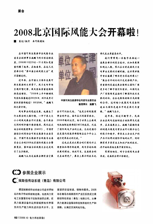
展会2008;115京■策划/执行本刊报道组国际风能大会开幕啦在中国可再生能源学会风能专业委员会副理事长施鹏飞的日程安排表里,2008年10月29日一51日用红笔重重的圈了起来,在他看来,在这几天里举办的“第四届全球风能大会”是不容错过的。
近年来,在中国大力倡导发展可再生能源的大背景下,风力发电市场呈现井喷之势,风电装机容量连续保持高速增长,“2008年上半年新增风电装机容量超过200万kw,到年底累计装机容量将超过100077kW。
”施鹏飞向记者介绍。
风电事业的迅速发展,也催生了行业展会的火爆行情。
一年下来大大小小的风电展会不计其数,各个展会之间的明争暗斗愈演愈烈,然而这次由全球风能理事会(G W EC).中国资源综合利用协会可再生能源专业委员会、中国可再生能源学会风能专业委员会主办的2008北京国际风能大会暨展览会、第四届全球风能大会还是吸引了众多眼球。
施鹏飞认为这届展会拥有其它展。
参展企业展示中国可再生能源学会风能专业委员会副理事长施鹏飞会不可比拟之处,“这是全球风能理事会的年会,每年在不同国家举办,2008年轮到北京。
由于世界上主要风电机组制造商都是G W E c的成员,代表了国际风电产业的主流,无论是国外还是国内风能界都能够在这个平台上进行更深层次的交流。
”这也正是此次展会吸引国内外主要整机和部件制造商、风电咨询机构参展的理由,由此可见,这届展会的代表面将更广、展会上展示的技术也埃斯倍传动系统(青岛)有限公司德国埃斯倍传动系统公司是世界知名的电子传动系统制造商,也是风力发电工业重要的电子控制系统供应商,在风力能源设备的运用领域拥有世界领先的生产能力和先进的技术水平,主522008.10电力系统装备I 要提供设备制造、销售和服务。
2005年在青岛市高新技术产业区投资成立埃斯倍传动系统(青岛)有限公司,从事风力能源设备驱动和控制系统的生产和销售,以满足亚洲风电市场。
将代表业界最高水平。
我们常常用一些数字来描述一届展会举办的是否成功,比如参展商和观众人数,然而在目前我国风力发电事业发展的关键时期,这些简单数字背后蕴藏了哪些更为深远的意义?。
律师帮您办门户:从无叶风扇知识产权问题谈起知识产权管理律师郑志锐浙江东孚律师事务所一直在关注无叶风扇产品知识产权问题的相关信息,最近就有两篇相关报道:英国《金融时报》报道的《山寨无叶风扇令戴森公司头痛》与《信息时报》报道的《怎么我们都在“山寨”?》。
这两篇报道都使用了“山寨”一词,且都作为贬义使用,本文不以道德来评判,同时也认为没有事实基础的道德评判是会令人展开不理智的推断,更何况涉及无叶风扇产品问题的事实更多的依赖于法律事实的确定,他与行为品德的判断具有很大的差异。
《山寨无叶风扇令戴森公司头痛》报道中指出:“据戴森公司表示,他们2008年就在中国申请气流倍增器的专利,但至今没有得到批复。
”这似乎在批判中国的专利保护制度,实际上,对发明专利的授权时间而言,这是很正常的,全世界很多国家都如此。
在几个月之前,我甚至有个观点:戴森公司对无叶风扇产品保护乏力,完全是源于对中国专利制度的无知和掌握、利用技能上的匮乏。
现今来看,戴森公司意识到了这个问题,但在行动上还仍不免乱抛牌,同时处处抱怨。
报道中同时指出:“在德国等许多地区,戴森公司不得不寻求销毁反工程仿冒产品,以保护自身品牌。
”说明在中国之外的德国等地,戴森公司遇到的问题也是差不多的。
总结相关的信息,对戴森公司而言,有以下三点:1、专利授权存在问题,包括能否授权与授权时间的快慢的问题;2、在世界各地大量存在非戴森公司出品的无叶风扇;3、戴森公司的维权情况不容乐观。
《怎么我们都在“山寨”?》报道中说及:“为什么在今年春交会上20余家工厂都有摆放(无叶风扇),但是遇到组委会检查就纷纷撤柜规避?”可以得出如下信息:1、全国至少有20余家工厂在生产销售无叶风扇(当然具体多少,不去查证,这并不不影响本文的分析);2、可能有无叶风扇相关权利人在展会上进行投诉;3、组委会的检查是发生一定作用的,结合投诉人是否出具有效权利凭证、是否提供侵权信息即是否进行有效的投诉,展会的情况一定会不同。
关于热敏电阻控制风扇的专利英文回答:In my opinion, a patent related to controlling a fan using a thermistor can be a valuable asset. This technology has the potential to improve energy efficiency and enhance the overall performance of cooling systems. By using a thermistor, the fan can automatically adjust its speed based on the temperature, ensuring optimal cooling without wasting excessive energy.One example of such a patent is a system that utilizes a thermistor to monitor the temperature of an electronic device, such as a computer or a server. The thermistor is strategically placed near the heat-generating components of the device. When the temperature exceeds a certain threshold, the thermistor triggers the fan to increase its speed, effectively dissipating the heat and preventing overheating.Additionally, the patent can include a control mechanism that allows the user to set specific temperature thresholds and fan speed levels. This way, the fan can be customized to meet the specific cooling requirements of different devices and environments. For example, in a noisy office environment, the user may prefer to set the fan speed to a lower level to minimize noise disturbance, while still maintaining adequate cooling.Furthermore, the patent can incorporate intelligent algorithms to optimize the fan control based on real-time temperature readings. For instance, the algorithm can analyze the rate at which the temperature is increasing or decreasing and adjust the fan speed accordingly. This dynamic control mechanism ensures that the fan responds quickly to temperature changes and provides efficient cooling.Overall, a patent related to controlling a fan using a thermistor can have significant commercial value. It can be applied in various industries, including electronics, automotive, and HVAC systems. The ability to automaticallyadjust fan speed based on temperature not only improves energy efficiency but also prolongs the lifespan of electronic devices by preventing overheating.中文回答:我认为,与使用热敏电阻控制风扇相关的专利可以成为一项有价值的资产。
专利名称:送风机以及空调机专利类型:发明专利
发明人:野村昌司
申请号:CN200810086743.X 申请日:20080320
公开号:CN101270758A
公开日:
20080924
专利内容由知识产权出版社提供
摘要:本发明提供一种送风机以及空调机,该送风机的结构如下:在外周具有叶片部的一端侧开口的叶轮杯的内部配置有电枢等。
并且,在电枢的轴向的一端侧配置有电路基板。
以覆盖电路基板、与叶轮杯的开口面对的方式配置基板盖。
并且,在叶轮杯的开口上安装有圆环状的环状体。
基板盖的延长部和环状体的突出部沿径向对置,从而形成微小缝隙(迷宫式密封)。
申请人:日本电产株式会社
地址:日本京都府京都市
国籍:JP
代理机构:北京三友知识产权代理有限公司
代理人:黄纶伟
更多信息请下载全文后查看。
专利名称:风机
专利类型:发明专利
发明人:吴开熔,吴沿,吴光明,吴洪寅,刘夫海,孟祥虎申请号:CN201510617072.5
申请日:20150925
公开号:CN105065295A
公开日:
20151118
专利内容由知识产权出版社提供
摘要:一种风机,风叶电机的传动轴伸入至外壳内并传动安装有旋转机构,旋转机构包括转盘,转盘侧面以转盘的旋转中心为中心等间距固定连接有多个重复设置的叶片,叶片为三角形,叶片所在三角形中角度最小的顶点靠近转盘的中心。
叶片相对于转盘的旋转半径倾斜设置。
叶片弯曲为圆弧形状。
叶片的数量为3个、4个、5个、6个、7个或8个。
叶片所在的三角形为直角三角形,该三角形的一条直角边与转盘相连接、另一条直角边与转盘互相垂直。
叶片所在三角形的其中之一个锐角为20~35°。
转盘侧面中心固定连接有分流锥,分流锥位于所有叶片所在三角形的最小锐角顶点之间。
分流锥为圆锥形。
进风通口处固定连通有进风筒,进风筒位于转盘外侧面。
申请人:枣庄市山亭区鑫盛机械厂
地址:277211 山东省枣庄市山亭区艾湖工业园
国籍:CN
代理机构:济南泉城专利商标事务所
代理人:李新锋
更多信息请下载全文后查看。
P ATENT N EWSLETTERN EW P UBLICATIONS W ORLDWIDE10.03.2008 Page 1 of 50Wind Energy AggregatesMonitoring Period:16.01. – 31.01.2008(JP, CN, KR, RU: 16.09. – 30.09.2008 )Applicant Page A B S K F (3)A H RE NS U WE (3)A ND E RS O N; TH OMA S (4)A PPA S U RI; A P PA K A RI (4)B U K TU K O V N I K O LA Y;B U K TU K O V B E I S E N;MO LD A B A E V A GU LN A Z;Z H A K Y PA IT MU K H A ME D (5)C A MP U S C RE A T E C O L TD (5)C A RD OS O RA I MU ND O NU NE S (6)C E N TRE N A TIO NA L D'E TU D E S S PA T IA LE S (C.N.E.S.) (6)C LI P PE R W IND PO WE R TE C H NO L OG Y, I NC (7)D A U B NE R & S TO M ME L GB R B A U-WE RK-P L A NU N G (7)E OL E OV E RS E A S C O M PA N Y L T D (8)FOS TE R S T E PH E N (9)GA ME S A I NNOV A TI O N & TE C H N OL OG Y (9)GE N E RA L E LE C TR IC C O (11)H A MI L TO N S U ND S T R A ND (14)H A NS E N T RA NS MIS S IONS IN T (14)H ITA C H I L TD (15)H ON G GU D U C K (17)INA B A D E NK I S E IS A K U S H O:K K (17)JONS S ON S TA N LE Y C (18)K A T RU E C O-I NV E N T I ONS PT Y L TD (18)K IM S E O M G GU (19)K OLA ROV, A ND RI JA (19)K ORE A C A S TI NG C O L TD (20)K ORE A E N E RG Y RE S E A RC H I NS T (21)LIE B H E R R-WE R K B I B E RA C H G M B H (21)MA N N H A R JI T (22)MA R INE S T RU C TU R E C ONS U L (22)MA TS U S H I TA E LE C TR IC I ND C O L TD (22)MIK A M I TA TS U YA (23)MI TS U B IS H I H E A V Y IND L TD (24)NA B T E S C O C OR P (26)NA GE L, H A NS H (27)NIS H I MA T S U C ONS T R C O L TD (27)NO RD E X E NE R G Y G M B H (28)NO RS K H Y D RO A S (31)NT N C O R P (31)PR OJ E C T, D E S IG N A ND TE C H N OL OG IC A L B U RE A U C ONC O RD L TD (34)RE PO WE R S YS TE MS A G (35)RH E I N, F R IE D R IC H, D IP L.-IN G.; MU TH, A LE X A ND E R (38)RI NTA JOU P PI YR JOE U OL E V I (39)RI T TE R, M A NU E L (39)ROZ LE V C OR P L LC (40)S.B. PA TE NT H O LD I NG A PS (40)S C A N W IN D GR OU P A S (41)S E IN TO A G E NC Y K K (41)S IE ME NS A G (42)S OH N C H E S TE R (43)TA IH E IY O C E ME NT C OR P (43)TH E Y, JA N (44)TOK YO E LE C TR IC PO WE R C O (44)TOS H IB A C OR P; TOS H IB A P LA N T S YS TE M S & S E RV I C E S C OR P (45)TS U RU MA K I YU IC H I R O (45)V E S TA S W IND S YS TE MS A/S (46)WI L LY V O GE L A G (47)WOB B E N A LO YS (48)YOS H I M OT O P OL E C O L TD (49)DE102006031527A117.01.2008AB SKFHorling, Peter; Olschewski, Armin; Kamm, Sandra; Wagner, ReinerSCHEIBE EINES DICHTSYSTEMSEine Scheibe eines Dichtsystems beinhaltet folgende Merkmale:- DieScheibe ist mit einem Zentralloch lochscheibenartig ausgebildet,- dieScheibe ist wenigstens drei Sektoren ausbildend geteilt gestaltet,-die Scheibe ist zum Befestigen an einer Planfläche vorgesehen und-wenigstens einer der Sektoren ist mit einem Langloch ausgebildet.Dadurch, dass die Scheibe wenigstens drei Sektoren ausbildend ge-teilt gestaltet ist, ist sie mit besonderem Vorteil einfach zu montierenund beispielsweise zu Wartungszwecken auch einfach zu demon-tieren, was insbesondere bei großen Außendurchmessern der Schei-be von besonderem Vorteil ist und weiterhin auch von besonderemVorteil ist, wenn das Dichtsystem beispielsweise einer Hauptlagerungeiner Windenergieanlage zugehört, die in einer Gondel auf einemTurm von zig Meter Höhe angeordnet ist, wo besonders beengtePlatzverhältnisse vorherrschen.WO08006413A1, 17.01.2008EP1878916A1, 16.01.2008AHRENS UWEAHRENS, UweWIND-OPERATED POWER GENERATORThe invention relates to a method for converting the kinetic energy contained in horizontal currents of naturally occurring fluids that float above ground to useful mechanical energy. At least one circulating element (1) is guided in aclosed cycle and is arran-ged substantially in a planeparallel to the ground. Onsaid element, at least twolengthwise adjustable trac-tion ropes (6, 7) and ortraction chains are fastenedin at least two substantiallyopposite positions. Saidropes or chains have buo-yancy elements (8) at theirfree ends, said buoyancyelements having respectivecross-sections for the cur-rent to impact. In a firstembodiment, a) a traction rope (7) which is fixed to a section (2) of the circulating element facing the direction of the horizontal current, when seen in the direction of circulation of the circulating element (1), and/or a traction chain is adjusted to be longer than said traction rope (6) and/or a traction chain which is fixed to a section (3) of the circulating element (1) facing away from the direction of the horizontal current, when seen in the direction of circulation of the circulating element (1), and b) the lengths of the traction rope (6, 7) in the region of the points of return (4, 5) of the circulating element (1) in which the course of the circulating element (4) relative to the horizontal current is reversed, when seen in the di-rection of circulation of the circulating element (4), are adapted in such a manner that they again meet the conditions mentioned under a). In a second embodiment, the respective cross-section of impact of the buoyancy elements (8) is varied in such a manner that the cross-section of impact of a buoyancy element (8) moving in the direction of the horizontal current is larger than the cross-section of impact of a buoyancy element (8) that moves in the opposite direction.US2008019832A124.01.2008ANDERSON; THOMASAnderson; ThomasTURBINE/ ROTORCRAFT/ OAR BLADEThe present invention generallyrelates to the field of blades thatmay be rotating, with a designproducing maximum drag whenencountering air/water flow inone direction, and either mini-mum drag, in the power genera-ting application, or maximum liftin the rotorcraft application whenencountering air/water flow in theopposite direction.WO07103270B124.01.2008APPA SURI; APPA KARIAPPA SURI; APPA KARIMETHODS AND DEVICES FOR IMPRO-VING EFFICIENCY OF WIND TURBINESIN LOW SPEED SITESThe present invention is for an apparatus and methodfor a passive pitchable device for wind turbines com-prising: a camshaft having cam grooves engraved; acylindrical shell; an axial compression spring; saidblade assembly and said cylindrical shell are fastenedtogether by screws; a plurality of balls that roll alongsaid cam grooves, and convert the axial displacementto rotation or pitch angle; and wherein the passivepitchable device ensures said blades are at the opti-mum angle of incidence in the stationary position; asthe rotor turns, the net force between centrifugal forceon said blade and the resistant force from said com-pression spring causes the device to move axial Iy outward while rotating to adjust the pitch of the rotor blade so that angle of incidence is optimal for the given wind speed; as the wind speed exceeds the de-sign speed and the centrifugal force on the rotor blade continues to increase, the device continues the move axially outward while rotating in the opposite direction as to adjust the pitch of the blade in the opposite direction so that the rotor performance is controlled and severe dynamic loads are avoided.17.01.2008BUKTUKOV NIKOLAY; BUKTUKOV BEISEN;MOLDABAEVA GULNAZ; ZHAKYP AITMUK-HAMEDBUKTUKOV, Nikolay; BUKTUKOV, Beisen; MOLDABAEVA,Gulnaz; ZHAKYP, AitmukhamedWIND POWER PLANT BUKTUKOV-3The invention relates to wind-power engineering. The inven-tive wind power plant comprises blades, the internal andexternal edges of each of which are chordwisely connectedat the end faces thereof by a rod, which is hingedly faste-ned, between the center and the external edge, to canti-levers which are set on a fixed axis by means of bearings.Each blade, at the butt ends between the center and theexternal edge, is hingedly connected to the adjacent bladeby means of a stem, wherein one end of the stem is con-nected to the blade between the center and the externaledge at the butt ends, whilst the other end thereof ishingedly connected to the rod of the adjacent blade betweenthe center and the external edge thereof, the rod of one ofblades being provided with a weight. In the other embodi-ment, the blades are hingedly fastened to the cantilevers atthe butt ends between the center and the external edge, theinternal and external edges of each blade at the butt endsare chordwisely interconnected by a stem, wherein one endof the stem is hingedly connected to the rod near the exter-nal edge, whilst the other end is connected to the adjacentblade between the rod center and the internal edge thereofor to the adjacent blade between the center and the internaledge, and one rod of one of blades is provided with aweight. The invention makes it possible to increase the useof wind power independently of the direction and speed thereof and to improve the reliability at stormy winds.JP2007239695A2CAMPUS CREATE CO LTDAZUMA YOSHIYUKI; TANAKA KAZUOWIND POWER GENERATORPROBLEM TO BE SOLVED: To provide a wind power generatorhaving improved generating efficiency while preventing itsbreakage under strong wind. SOLUTION: The wind power gen-erator comprises a main shaft 2, a blade 4 to be rotatedaround the main shaft, and angle of attack control mechanisms5, 6, 11, 12 for changing the angle of attack of the blade de-pending on the rotating angle. Each of the angle of attack con-trol mechanisms has an eccentric shaft 5 arranged in the stateof being eccentric from the main shaft for changing the direc-tion of the resultant force of air produced on the blade by therotation of the eccentric shaft around the main shaft. It con-sists of a wind direction detecting member 13 to be displacedfor keeping it in a stationary state when arranged in a prede-termined direction relative to the flowing direction of wind andfor keeping it is in the state of being arranged in thepredetermined direction when arranged in a direction different from the predetermined direction, a lift generating member 14 mounted on the wind direction detecting member for generating upward lift when receiving wind, and a converting member 16 supporting the wind direction detecting member movably up and down for converting the move-up of the wind direction detecting member into the rotation of the eccentric shaft. COPYRIGHT: (C)2007,JPO&INPITBRI0606462A29.01.2008CARDOSO RAIMUNDO NUNESCARDOSO RAIMUNDO NUNESGERADOR EÓLICO DE ALTITUDEGERADOR EóLICO DE ALTITUDE. Patente de Modelo de Utilidade para um gerador eólico de altitude que é compreendido por um gerador eólico (7) acoplada ao corpo de um dirigível (1), que será estacionado em altitudes de pressão que vão desde 20.000 pés até 35.000 pés dependendo da altitude das correntes de jato no momento da operação para coletar a energia cinética dos fortes ventos em altitudes presentes na chamada Circulação Geral Superior chamados de correntes de jato e convertê-la em energia elétrica podendo ainda, um mesmo dirigível, conter mais de um gerador eólico em função do projeto e da estrutura de ambos (dirigível e gerador).WO08012420A2, 31.01.2008FR2904062A1, 25.01.2008CENTRE NATIONAL D'ETUDES SPATIALES (C.N.E.S.)DESPLATS, Romain; FEVRIER, FrédéricWIND-POWERED DEVICE FOR PRODUCING ELECTRICAL ENERGYThe invention relates to a wind-powered device for producing electrical energy, comprising an electric generator set (1) which works by converting mechanical energy into this electrical energy, a wind-powered set (3) designed to capture the energy of the wind and convert it into mechanical energy, a transmission (2) positio-ned between said wind-powered set (3) and saidgenerator set (1), saidtransmission (2) beingdesigned to transmit me-chanical energy producedby said wind-powered set(3) to said generator set(1), characterized in thatsaid wind-powered set(3) comprises at leasttwo air turbines known aswind turbines (4) com-prising non-coaxial shafts(5) coupled to thetransmission (3), saidwind turbines (4) beingdesigned in such a wayas to present an equiva-lent surface area to thewind that exceeds the surface area exposed to the wind of each of the wind turbines (4).WO08012615A231.01.2008CLIPPER WINDPOWER TECHNOLOGY, INC DEHLSEN, James, G., P.RETRACTABLE ROTOR BLADE STRUCTUREA power generating system wherein a turbine (5) is mountedon top of a tower (4) or tethered underwater. The turbine (5) includes a rotor (6) having a main blade (7) connected to a rotor hub (9) and an extender section (2). An adjusting device positions the extender blade between a retracted position with-in the main blade and to an extended position to expose moreor less of the rotor to the fluid flow. An extendible rotor blade structure provides support for an airfoil shell by extending a structural beam of a base blade portion (8) of said rotor blade through to a telescoping module of said blade, both when an extender blade portion (2) of said rotor blade is retracted and extended.EP1882853A230.01.2008DAUBNER & STOMMEL GBR BAU-WERK-PLANUNG Stommel, MatthiasWIND TURBINE AND ME-THOD FOR OPERATING AWIND TURBINEDie Erfindung betrifft ein Verfahrenzum Betreiben einer Windenergieanla-ge mit einem von Wind antreibbarenRotor (18) mit zumindest einem Rotor-blatt (22), mit einem Generator zurUmwandlung der mechanischen Ener-gie des Rotors (18) in elektrische E-nergie sowie mit einem Turm (14), andem der Rotor (18) angeordnet ist. ZurAbspannung der Windenergieanlage(10) wird eine Abspannvorrichtung be-darfsweise automatisch von einem un-gespannten Zustand in einen gespann-ten, die Windenergieanlage (10) stabi-lisierenden Zustand überführt.24.01.2008DAUBNER & STOMMEL GBR BAU-WERK-PLANUNG Stommel, MatthiasWINDENERGIEANLAGE UND VERFAHREN ZUM BE-TREIBEN DER WINDENERGIEANLAGEDie Erfindung betrifft eine Windenergieanlage (10) mit einem von Wind antreibbaren Rotor (18) mit zumindest einem Rotorblatt (22), mit einem Generator zur Umwandlung der mechanischen Energie des Rotors (18) in elektrische Energie sowie mit einem Turm (14), an dem der Rotor (18) angeordnet ist. Die Windenergieanlage (10) weist außerhalb des Turms (14) einen Aufzug (30) zum Befördern von Personen und/oder Gegen-ständen auf, vorzugsweise einen Personenaufzug.FR2903739A118.01.2008EOLE OVERSEAS COMPANY LTDAMRAM RAOULDISPOSITIF ET PROCEDE DE DEMONTAGE RA-PIDE D'UN ROTOR ET D'UNE NACELLE DU MATD'UNE EOLIENNE,AINSI QU'UNE EOLIENNE POURVUE D'UN TEL DISPOSITIFLe dispositif comprend un ensemble formé (6) par une grue (7)montée sur un support (8) apte à coulisser le long du mât (1) del'éolienne sur des rails de guidage (9, 10) fixés à demeure d'uncôté du mât (1) et permettant audit ensemble grue-support (6) dese déplacer le long du mât à l'aide de moyens de levage (11, 12)au moins partiellement intégrés dans celui-ci, et des moyens deblocage dudit ensemble grue-support en haut du mât.GB2440264A, 23.01.2008WO08009920A2, 24.01.2008FOSTER STEPHENFOSTER STEPHENWIND POWER ASSEMBLYIn a first aspect of the invention a wind power assemblycomprises a channel 826 with a turbine rotor 836 mountedtherein, air passing across/through the channel 826 drivingthe rotor 836. The channel 826 may be a recess formedacross the apex or ridge 206 of a pitched structure 200(e.g. a roof) and may be U, V or L shaped. The rotor 836may be mounted on a support 880 which is at an anglesuch that the blades rotate in a plane at least 5° off ver-tical. In a second aspect of the invention a wind powerassembly comprises at least one inclined passage (112,figure 1) which directs air to a turbine rotor (130, figure 1) mounted on an inclined structure (200, figure 1) such as a roof. In each aspect of the invention the turbine rotor 836, (130) may be rotatable about a vertical axis so as to face into a prevailing wind, and the whole assembly may be retro-fitted onto an existing pitched structure 200.ES2265760BA, 16.01.2008EP1878915A2, 16.01.2008GAMESA INNOVATION & TECHNO-LOGYLLORENTE GONZALEZ JOSE IGNACIO; VELEZORIA SERGIOBLADE FOR WIND-POWER GENERA-TORSThe invention relates to a blade for wind-powergenerators. The inventive blade is divided trans-versely into two or more independent sections,each section comprising aerodynamic skins orwalls (3) and an inner longitudinal reinforcingstructure (4). In addition, the ends of the afore-mentioned sections are equipped with connectionmeans comprising metal inserts (10) which arehoused and fixed axially inside the walls of theinner longitudinal resistant structure.ES2265771BA16.01.2008GAMESA INNOVATION &TECHNOLOGYLLORENTE GONZALEZ JOSE IGNACIOMETHOD OF MAINTAININGWIND TURBINE COMPONENTSOPERATIONAL AND A TUR-BINE COMPRISING COMPO-NENTS SUITABLE FOR OPERA-TIONAL MAINTENANCEThe invention relates to a wind turbine (1)which is connected to an electrical powergrid (23) and which uses a magnet genera-tor (6) as the only electrical power gene-rator element both in the normal operationthereof and during periods in which theturbine is disconnected from the electricalpower grid. The aforementioned wind tur-bine can perform operations in order to maintain the wind turbine systems operational, with the contin-ued generation of electrical power, and to adjust the quantity of electrical power produced for power consumption during the periods in which the turbine is disconnected from the electrical power grid.EP1881195A123.01.2008GAMESA INNOVATION & TECHNO-LOGYLLORENTE GONZÁLEZ, José I., GAMESA EÓLICA,SAU.TOOL FOR PREVENTING THE VOR-TEX EFFECTThe invention relates to a tool for preventing thevortex effect, comprising three corrugated tubeswhich extend helically from the upper end (2) ofthe tower (3), such as to cover only the upperpart thereof. The helix pitch defined by thecorrugated tube (1) along the length of thetower (3) is fixed using cords (5) which are attached at each revolution of the tube. The corrugated tube (1) is lifted with a cathead (6) which is disposed on the structure that is used to anchor (4) the tool to the tower (3), said structure comprising three T-shaped sections which form an X having sectors (9) fixed to the ends thereof. In addition, four legs (14) are welded to the aforementioned sectors and the tubes are wound around said legs.DE102007033669A124.01.2008GENERAL ELECTRIC CO.Kraemer, SebastianSYSTEM UND VERFAHREN ZUR BLITZDETEKTIONEs wird ein System (10) zur Blitzdetektion bereitgestellt. Das Blitzdetektionssystem (10) enthält einen Leiter (18). der zum Aufnehmen eines Blitzschlages (12) und zum Ableiten eines blitzreduzierten Stroms (16) angepasst ist. Das System (10) enthält auch einen faseroptischen Stromsensor (22), der dafür an-gepasst ist, mehrere Blitzparameter aus dem blitzreduzierten Strom (16) zu detektieren und ein Strah-lungsbündel (24) in Reaktion darauf zu modulieren. Das System (10) enthält ferner ein elektrooptisches Modul (28), das dafür angepasst ist, das Strahlungsbündel (24) aus dem faseroptischen Stromsensor (22) zu empfangen und zu einem elektrischen Signal (32) umzuwandeln.US732122122.01.2008GENERAL ELECTRIC COMPANYBücker; Andreas; Janssen; Wilhelm; Lütze; HenningMETHOD FOR OPERATING A WINDPOWER PLANT AND METHOD FOROPERATING ITA method of operating a wind turbine, wherein thewind turbine may include rotor windings of an induc-tion generator, which includes stator coils coupled toa voltage grid, fed with rotor currents by a feed-inunit are driven by a rotor of the wind turbine;wherein the frequencies of the fed-in rotor currentsare controlled depending on the rotor rotation fre-quency and the feed-in unit is electrically decoupledfrom the rotor windings in the case predeterminedvariations of the grid voltage amplitude and the rotorcurrent feed-in is resumed after the decouplingcaused by the variation of the grid voltage amplitude, when the currents generated in the motor wind-ings by the variation have declined to a predetermined value.US732279429.01.2008GENERAL ELECTRICCOMPANYLeMieux; David L.; Moroz; Emil MMETHOD AND APPARA-TUS FOR CONDITION-BASED MONITORING OFWIND TURBINE COMPO-NENTSCondition-based monitoring functio-nality using sensors that monitorwind turbine component move-ment. A main shaft flange displace-ment sensor system can be used toprovide signals used to perform fa-tigue assessment of the wind tur-bine rotor blades as well as drivetrain components. Output signalsfrom the main shaft flange dis-placement sensor system are usedto perform fatigue assessment, fai-lure trending, diagnostic analysis,etc.US2008015816A117.01.2008GENERAL ELECTRIC COMPANY Jammu; Vinay Bhaskar; Vora; Nishith Pramod; Babu; Ravi Yoganatha; Mahajanam; Rama Venkata MONITORING SYSTEM AND METHOD A system includes an analysis module and/or a prediction module. The analysis module receives data from a heat transfer device, and can compute a performance indicator indicative of an incipient anomaly condition of the heat transfer device based upon the received data, and/or can compute a nor-malized efficiency of the heat transfer device. The normalized efficiency represents a corrected effici-ency that isolates effects of a process parameter on performance of the heat transfer device. The data represents a measurable process parameter or a change in a measurable process parameter in the heat transfer device. The prediction module receives the data and computes a performance indicator to predict performance degradation of the heat trans-fer device over time based upon the received data. Associated methods are provided.US732279829.01.2008GENERAL ELECTRIC COMPANYCairo; Ronald RalphHIGH STRUCTURAL EFFICIENCY BLA-DES AND DEVICES USING SAMEA blade for a rotor has integral stiffeners with at leastone of unidirectional caps configured to carry bladebending loads in axial tension or webs to carry trans-verse shear resulting from blade bending.EP1881194A123.01.2008GENERAL ELECTRIC COMPANYNies, JacobCOOLING DEVICEA cooling device (100) for a wind turbine is provided, thecooling device (100) comprising at least one liquid-tighttube (110) which is partially filled with a liquid coolant(120), wherein one end (112) of the tube (110) islocated in a first area and another end (114) of the tube(110) is located in a second area, the first and secondareas having different temperatures when operating thewind turbine.EP1882854A230.01.2008GENERAL ELECTRICCOMPANYRogail, PeterAPPARATUS FOR ASSEM-BLING ROTARY MACHI-NESA wind turbine generator (124)includes at least one blade and ahub assembly (104). The hub as-sembly includes at least onesubstantially cylindrical wall (140)defining a substantially annular hubcavity (120). The assembly alsoincludes at least one substantiallytriangular frame inserted into thehub cavity and is fixedly coupled tothe cylindrical wall. The assembly further includes at least one blade attachment apparatus having at least one blade support sleeve (112) fixedly coupled to at least a portion of the cylindrical wall. The sleeve is configured to receive at least a portion of the wind turbine blade. The blade attachment appara-tus also includes at least one blade pitch bearing (160) having a blade portion (166) and a hub portion (164). The hub portion is slidingly engaged with the blade portion blade portion and the blade portion is positioned radially outboard of the hub portion.US2008012346A117.01.2008HAMILTON SUNDSTRANDBertolotti; Fabio PaoloWIND-TURBINE WITH LOAD-CAR-RYING SKINA horizontal axis wind-turbine includes a statio-nary support structure, a two-bladed rotor sup-ported by the stationary support structure, and ahollow shaft rotationally attached to the statio-nary support structure through a bearing. Teeterhinges are spaced apart from each other andconnect the hollow shaft to a rotor-hub to allow ateetering action of the rotor-hub with respect tothe hollow shaft. The hollow shaft structurallysupports the two-bladed rotor with respect to thestationary support structure, with a maximumouter diameter of the hollow shaft being greaterthan an outer diameter of the bearing.DK1373720T321.01.2008HANSEN TRANSMISSIONS INTCHRISTENSEN MOGENSWIND TURBINE COMPRISING A PLA-NETARY GEARA wind turbine with a rotor, a nacelle and a tower.The nacelle comprises a planetary gear (4) with aplanetary holder (5), on which the hub (6) of therotor is rigidly secured, and which can be connec-ted to the shaft of an electrice generator. The pla-netary gear (4) comprises a ring gear (7) fixedlymounted on an engine frame (9) in the nacelle oron the member (8) rigidly connected to saidframe. The planetary wheels (17a, 17b) of the pla-netary gear can run around a centrally arrangedsun wheel (14) while engaging the latter. The sunwheel is optionally connected to a parallel gear (30). The planetary holder (5) is rotatably mounted in the ring gear (7) by means of at least two sets (17) of planetary twin wheels (17a, 17b). Each set of plane-tary twin wheels is mounted on a bogie shaft (19) on the planetary holder. Through an axially rearward collar (23) projected beyond the ring gear, the planetary holder (5) is also rotatably arranged on the curved outer side (7b) of the ring gear (7) by means of an outer radial-axial-roller bearing (27).JP2007252028A227.09.2007HITACHI LTDOHARA SHINYA; ICHINOSE MASAYA;FUTAMI MOTOO; MATSUTAKE MIT-SUGI; FUJII KAZUMI; IDE KAZUMA-SA; ITABASHI TAKESHI; TAMURAJUNJIWIND POWER HYDROGENPRODUCTION SYSTEMPROBLEM TO BE SOLVED: To providea wind power hydrogen productionsystem wherein a power converter isso controlled that a time for which awind turbine generator is in an operable range is lengthened and a time for which hydrogen is produced is thereby lengthened. SOLUTION: The wind power hydrogen production system is so constructed that the following operation is performed. According to the rotational speed of the wind turbine generator, an amount of current supplied to an electrolytic hydrogen production system is varied to reduce fluctuation in number of rotations. Further, according to rotational speed, the pitch angle of the wind turbine gen-erator is varied to reduce fluctuation in the number of rotations of the wind turbine generator. Power for startup is obtained using a permanent-magnet generator as the generator for the wind turbine genera-tor. Or, a power storage device is supplementarily added for assisting startup. Or, only control power is supplied from a system. COPYRIGHT: (C)2007,JPO&INPITJP2007249341A227.09.2007HITACHI LTDFUJII KAZUMI; ICHINOSE MASAYA;FUTAMI MOTOO; IDE KAZUMASA;ITABASHI TAKESHI; TAMURA JUNJIHYDROGEN PRODUCTIONSYSTEMPROBLEM TO BE SOLVED: To provide awind power generation and hydrogenproduction system that stably suppliespower from a wind power generation de-vice to a load and a hydrogen productiondevice. SOLUTION: The absorption of po-wer fluctuations of the wind power ge-neration device in the hydrogen pro-duction device and the control of the cur-rent of the hydrogen production devicecan stabilize hydrogen production andsuppress hydrogen production devicedegradation.COPYRIGHT: (C)2007,JPO&INPIT。