GPS-01系列说明书V1.1
- 格式:pdf
- 大小:226.94 KB
- 文档页数:19
目录第一章华星RTK GPS系统概述 (3)§1.1 华星RTK GPS系统创新技术 (3)§1.2 技术参数与性能特点 (4)§1.3数据传输模式 (6)§1.4基准站示意图 (8)§1.5移动站示意图 (10)第二章接收机设置 (13)§2.1工作模式 (13)§2.2 控制面板说明 (13)第三章数据链电台 (16)第四章电源 (26)§4.1 电池充电 (26)§4.2 锂电池安装与拆卸方法 (26)第五章内置GPRS模块 (29)§5.1安装SIM卡 (30)§5.2拆卸SIM卡 (30)第六章静态测量数据下载 (31)§6.1数据下载 (31)§6.2接收机管理软件 (32)第七章作业模式 (34)§7.1使用URS电台作业 (34)§7.2使用内置GPRS数据链作业 (35)§7.3 水上测量 (36)§7.4 双频静态测量 (37)第八章注意事项 (39)第九章华星GIS+数据采集器 (40)§9.1认识华星GIS+数据采集器 (40)§9.2如何取出和安装电池 (42)§9.3如何取出和放入触摸笔 (43)§9.4如何开机 (44)§9.5如何获取数据到电脑 (44)§9.6如何安装和取出MicroSD卡 (47)第一章华星RTK GPS系统概述华星RTK GPS是广州华星定位技术有限公司创新推出全新一代基于CORS技术的RTK系统。
系统采用超长距离RTK技术,第三代GPS卫星L5信号接收技术。
系统引入语音智能技术实现“语音导航操作”,对仪器主机操作全过程语音提示;融入U盘式文件管理技术,拖拽式文件下载;一体化全内置加固机身,军标三防设计,更适应野外环境的细节考虑;成熟的GSM/CDMA网络传输技术,GSM/CDMA/UHF轻松一键切换。
GPS驯服钟GPS DISCIPLINED OSCILLATORGPSDO使用说明书V1.1 USER MANUAL V1.12016@BG7TBL版权所有。
保留所有权,中国印刷**************************************.PrintedinCHINA该用户手册描述如何安装和使用GPS驯服钟。
This manual describes how to install and use GPS Disciplined Oscillator (GPSDO).如需帮助,请联系For assistance, please contact梧桐电子WUTONG electronic中国广东深圳龙华longhua Shenzhen Guangdong CHINA网址:Website: 电话:134****9750TEL: 0086-134 **** ****Q Q: 1630 2767Email: **************** / *************/**************日期:2016-04-08Date: 2016-04-08目录Contents一,特点, Key Features (5)二,概述, Overview (6)三,技术参数, (7)四,设备安装,使用,Installation (10)4.1设备面板,Front panel (10)4.2和电脑连线, Connect PC (11)4.3工作状态,Normal Usage (12)4.4使用注意事项,Usage Notes (12)六,常见问题问答FAQ (15)一,特点Key Features1,输出10MHz高精度正弦波或方波,噪音低Output 10MHz high accuracy sine or square wave signal, low noise2,输出1PPS秒脉冲信号,和UTC时间同步,Output 1PPS second pulse, in sync with UTC time3,GPS灵敏度高,一线天也可锁定Highly sensitive GPS receiver,needs only few satellites for signal lock4,带锁定指示,红灯灭即可使用With lock indicator, red LED OFF => equipment locked5,供电简易,单12V/1.5A即可,可使用开关电源Power supply 12VDC/1.5A, simple & easy,may use switched power supply 6,价格低廉,体积小,使用方便,Inexpensive, small size, convenient to use7,特有的去除GPS信号抖动算法,精度更高Unique algorithm for removal of GPS signal jitter for higher accuracy二,概述OverviewGPSDO英文名GPS Disciplined Oscillator, 中文名称GPS驯服钟。
Hellognss-OrionGPS教学平台产品说明书V1.0北京星源北斗导航技术有限责任公司2010 年 7 月 20 日Item ContextAuthor hgLast Update 2010-7-20Version 1.0Copyright(c) 星源北斗公司密级对外交流星源北斗公司主要产品信息:1、Hellognss-MG5001开发套件/product/part/2010-01-11/11.html2、Hellognss-Orion教学平台/product/part/2010-01-01/9.html3、HG-SoftGPS02中频信号采集器/product/part/2010-04-22/14.html4、HG-ARMGPS商业开源软件V1.1/product/soft/2010-03-25/13.html更多详细信息请致电星源北斗咨询!公司地址:北京市海淀区海淀中街16号中关村公馆B座802室电话及传真:824840621 产品概述Hellognss-Orion的命名是为了纪念Zarlink的Orion硬件。
接收机的核心部分HG-RE01的主要设计也来源于Orion,实际性能也和Orion相当。
Hellognss-Orion硬件由三个部分组成:HG-ISACARD、HG-RE01( GP2015+GP2021 )和ISA主机。
图1 HG-RE01+HG-ISACARD插卡图2 ISA主机Hellognss-Orion和PC搭配销售,以降低客户安装系统的难度。
为了让更多的人可以单步调试OpenSourceGPS和HG-DJGPS,星源北斗用了一个月时间专门寻找具有ISA接口的PC主机。
最终将找到的主机和Hellognss-Orion联调成功,主机性能卓越,主频甚至可达2.4G,可以算是GNSS接收机开发套件的顶级配置。
HG-ISACARD采用金手指保证信号可靠连接。
Hellognss-Orion是国内唯一可以买到的、廉价的、支持OpenSourceGPS和HG-DJGPS 开源代码的硬件接收机。
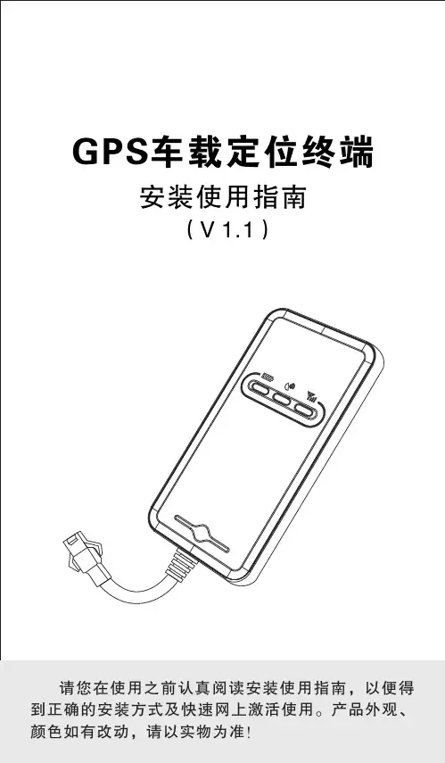
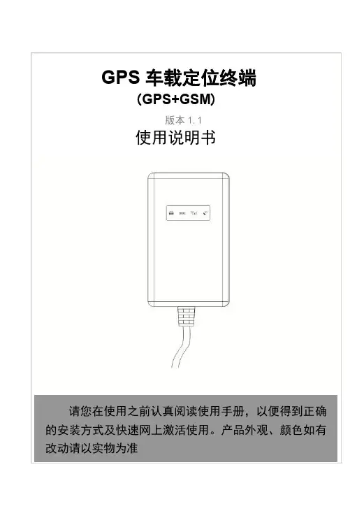
6.4 隐藏式安装,电源连接线选用原厂提供的电源适配线(如产品配件图),红线端串有熔丝盒(2A FUSE)可起到短路过流保护。
七、终端工作7.1 开机:终端上电自动开机。
此时红色电源指示灯闪亮表示电源正常供电,GPS蓝色指示灯和GSM绿色指示灯闪亮表示信号搜索中。
终端正常工作后红色电源指示灯闪亮,蓝色GPS指示灯长亮(表示GPS已定位),绿色GSM指示灯长亮(表示GPRS上线)。
此时终端每隔定时时间(默认10s)向服务平台上传一次当前位置信息,当车辆长时间处于静止状态时,终端会自动进入省电模式并启动静态漂移抑制机制,从而有效控制GPS静态漂移数据上传问题,使终端工作更省电、更智能、轨迹更准确。
7.2 关机:拔掉电源插头,终端断电后关机。
八、侧按键功能在正常工作指示状态下,若按下侧按键,此时三个指示灯会同时熄灭进入隐蔽工作状态,当再次按下侧按键时三个指示灯恢复正常指示。
一旦按过侧按键,终端会有记忆功能,下次重新上电启动时,待终端稳定工作后会自动进入隐蔽工作状态,此时指示灯不亮是属正常现象。
●若有接通并听到“嘟…嘟…”声时。
终端SIM卡安装正确且尚有余额,请咨询此卡的运营商是否有开通GPRS功能;你也可以将终端的SIM卡拆下,装入手机试验,看能否上网浏览网页;否则应没有开通GPRS服务,请联络运营商为您开通GPRS。
●若没有接通提示终端已关机时。
此时必须召回汽车来检查终端的工作状态,处理步骤如下:a)检查红色电源指示灯是否闪亮,若不亮请检查终端接线处是否脱落或电源接线端保险丝烧断;也可以用万用表测量主电源线2P连接器端的电压,若电压正常,此时请拆下终端机并寄给您的经销商返原厂维修。
b)若红色电源指示灯闪亮,绿色GSM指示灯不亮,此时请检查SIM卡是否正确安装,如果安装没有问题请更换另一张SIM卡来使用。
11.1.2 观察终端掉线区域,是个别掉线还是全部掉线,以判定是否为运营商网络问题;11.2 当GPS信号接收异常时,请开车到较开阔的地方来定位,一般首次定位时间需要1-2分钟。

GPS Tracker ManualGT011.Install mobile phone cardSelect the SIM card(in maximum size) with GSM (GPRS) network.Open cover with screwdriver, insert the SIM card( shown as the below right picture). The device default shut down, insert the phone card automatically power on.After you insert your cell phone card, please dial the SIM card mobile phone number, after dial tone, then hang up the device, which means normal reading card.2.WiringRed is positive, black is negative yellow is ACCBattery voltage: DC 12-100V3.LED StatusOrange LED--- GSM signal statusLight On = GSM network connected Flash =GSM network searching or No SIM cardBlue LED: GPS signal statusLight On = GPS positioned Flash = No GPS Signal or GPS searchingRed LED: Battery statusFlash = Working Light Off = No Power4.Set APNFirst, setting up APN (If incorrect setting of APN, could not use the monitoring platform). If you are unsure of the SIM card APN you are using, please call the operator.For examples:APN=cmnet APN User name=blank APN Password=blankType message: apm123456 cmnet reply: apn okAPN=Internet APN User name=gprs APN Password=0000Type message: apm123456 internet reply: apn okType message: apmuser123456 gprs reply: apnuser okType message: apm123456 0000 reply: apnpasswd ok5.Monitoring platformLog in Input tracker ID number:APP download;IOS AndroidLog in as the below pictures show6.Set IPIf you want to use the custom monitoring platform, please change the IP address and port number in the following instruction format.Instruction format: ip+ space + IP address + space + portExample: IP 106.3.230.234 8185 (this IP address is default to the device)Reply: SET OK7.Set authorization numberThe authorization number has the main authorization number and the secondary authorization number. Only the main authorization number can modify the password and send the modification instructions.Setthemainauthorizationnumber:101#138****8000#Settingthesecondaryauthorizationnumber:102#138****8001#Settingthesecondarynumber:103#138****8002#Query authorization number: C10#, the device replies as follows: 101#138****8000 102#13800138001103#138****8002No more than 2 secondary authorization numbers are allowed to set. After the authorization number is set, only the authorized number can send command, and the unauthorized number can not send. After setting the authorization number, all alerts can be sent to the authorization number.8.ACC settingThe orange ACC line must be properly connected.Connecting the ACC line when the engine is at start state, the the equipment will be into non alarm state automatically. If the ACC line is switched on when the engine is switched off, the device automatically enters a state of fortification.Fortification status: turn on the engine to start the alarm to the authorized number.Non alarm state: turn off the engine alarm.You can use SMS or platform to send instructions to the equipment for non alarm and alarm(fortification) settings, set as follows:Fortification: ACCLOCK, 123456,1 device reply: set successfullyNon alarm: ACCLOCK, 123456,0 device reply: set successfully9. Vibration alarm functionThe tracker is equipped with a vibration sensor, vibration alarm can be set to SMS alarm and telephone call alarm, the setting method is as follows;SMS alarm: 125# delete this setting: 126#Telephone alarm: 122# removes this setting: 121# (device is without microphone, can not hear the sound from car)10.SMS alarm switchIf you do not need SMS alarm, avoid harassment, you can set as follows;Close SMS alarm, edit SMS and send: CF Open SMS alarm: SF11.Change the passwordModify the command password, edit SMS and send: password123456 666888 to your device phone number, device reply: password OK (666888 is your new password)12.Over speed alarm functionSet the maximum speed value of your vehicle. If it is overspeeding, it will send an alarm message or call 3 authorization numbers. The setting method is shown as follows;Turn on over speed alarm: edit SMS and send: speed123456 080 (080: maximum speed limit 80 km / h),device reply: speed OKShutdown over speed alarm: edit SMS and send: speed123456 000,device reply: speed OK13.Electronic fenceWith the current vehicle as the center, a circular electronic fence can be set up for vehicle movement for alarm. The setting method is shown as follows:Turn on the electronic fence, edit message and send: move 300 (300:300 meters radius) device reply: move OK14.Assistant instruction1.1Restore factory settings,text and send:FORMATDevice reply:Restore factory value successfully.Please reset the owner's number!1.2Query device information:CXZTReply:XM_GT09_SW_20.0 2017/03/13ID:6170711018IP:106.3.230.225 8185BA T:3APN:CMMTMGPS:A-25-00GSM:17ICC89860116851015935693Frequently-used Command。
InHand VG710 车载网关用户手册 V1.1InHand VG710车载网关用户手册资料版本:V1.0—2022.02声明首先非常感谢您选择本公司产品!在使用前,请您仔细阅读本用户手册。
非本公司书面许可,任何单位和个人不得擅自摘抄、复制本书内容的部分或全部,并不得以任何形式传播。
由于不断更新,本公司不能承诺本资料与实际产品一致,同时也不承担由于实际技术参数与本资料不符所导致的任何争议,任何改动恕不提前通知。
本公司保留最终更改权和解释权。
版权所有©2020北京映翰通网络技术股份有限公司及其许可者版权所有,保留一切权利。
本手册图形界面约定技术支持联络信息北京映翰通网络技术股份有限公司(总部)电话:************地址:北京市朝阳区紫月路18号院3号楼5层成都办事处电话:************地址:四川省成都市高新区府城大道西段399号,天府新谷10栋1406室广州办事处电话:************地址:广州市天河区棠东东路5号远洋新三板创意园B-130单元武汉办事处电话:************地址:湖北省武汉市洪山区珞瑜东路2号巴黎豪庭11栋2001室上海办事处电话:************地址:上海市普陀区顺义路18号1103室目录1 简介 12 硬件部分 22.1 指示灯说明 22.2 通过Reset按钮恢复出厂 33 默认配置 44 登录联网 64.1 设备通过拨号卡接入网络 64.2 Wi-Fi接入网络 85 网络管理 105.1 网络 105.1.1 桥接口 105.1.2 VLAN接口 115.1.3 ADSL拨号(PPPoE) 125.1.4 Wi-Fi 125.1.5 环回接口 145.1.6 二层交换 145.2 车辆诊断 155.3 VPN应用 175.3.1 IPsec 175.3.2 GRE 205.3.3 L2TP 215.3.4 OpenVPN 225.3.5 证书管理 235.4 服务 265.4.1 DHCP(自动获取IP地址) 26 5.4.2 DNS(域名解析) 275.4.3 DDNS(动态域名) 285.4.4 短信服务 305.4.5 GPS 305.4.6 QoS 335.4.7 流量控制 345.5 防火墙 355.5.1 访问控制(ACL) 355.5.2 网络地址转换(NAT) 375.5.3 MAC-IP绑定 385.6 路由 395.6.1 静态路由 395.6.2 动态路由 405.7 链路备份 445.7.1 SLA 445.7.2 Track模块 445.7.3 VRRP 465.7.4 接口备份 485.8 快速向导 515.8.1 新建拨号 515.8.2 新建IPsec隧道 51 5.8.3 IPsec专家配置 52 5.8.4 新建L2TPv2隧道 525.8.5 新建端口映射 536 APP管理 557 网关连接到云平台 568 工业接口(串口) 57 8.1 DTU 578.2 IO接口 609 系统管理 619.1 系统 619.2 系统时间 629.3 管理服务 639.4 用户管理 649.5 AAA 649.5.1 Radius 659.5.2 Tacacs+ 659.5.3 LDAP 669.5.4 AAA认证 679.6 配置管理 689.7 SNMP 689.7.1 SNMP 689.7.2 SnmpTrap(告警) 69 9.7.3 SnmpMibs 709.8 告警 719.9 系统日志 739.10 系统升级 749.11 重启系统 7410 诊断工具 761 简介InHand VG710车载网关是面向车联网领域推出的新一代4G车载网关,该产品为汽车和运输服务车辆提供高速安全的网络,满足警用车辆,应急指挥车辆,工程车辆,医疗车辆以及物流车辆等移动高速网络需求,搭配基于云的远程车辆管理平台,为物流管理、资产跟踪、移动办公以及政府安全等工作提供随处可达的网络和不间断的运营监管。
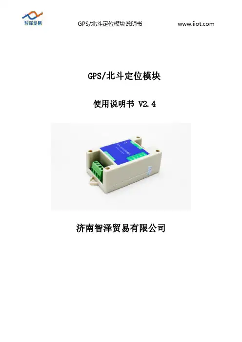
GPS/北斗定位模块说明书GPS/北斗定位模块使用说明书V2.4济南智泽贸易有限公司目录1.产品介绍 (1)1.1.产品概述 (1)1.2.产品特点 (1)1.3.技术指标 (1)1.4.产品尺寸 (1)1.5.硬件接口 (2)2.通信协议 (3)2.1.通信协议 (3)2.2.寄存器定义 (4)3.协议详解 (6)3.1.读保持寄存器 (6)3.2.读取版本号 (6)3.3.读取设备地址 (7)3.4.读取设备波特率 (7)3.5.读取奇偶校验位 (7)3.6.读取定位数据(RMC) (8)3.7.定位数据(RMC)解析 (8)3.8.修改设备地址(广播) (9)3.9.修改波特率 (9)3.10.修改奇偶校验位 (9)4.保修期限 (10)5.技术支持 (10)6.联系方式 (10)7.免责声明 (10)1.产品介绍1.1.产品概述GPS/北斗定位模块,是一款具有GPS定位和北斗定位的双模定位终端,可以快速、精确定位位置。
定位模块内含双模定位芯片,快速定位位置,并且将定位信息以RS485接口和Modbus协议的方式提供给用户使用,串口波特率最高可达115200bps,可以通过PC机设置软件或串口命令轻松控制,使用方便快捷。
1.2.产品特点⏹同时支持GPS定位和北斗定位⏹串口波特率自定义,支持2400~115200bps⏹串口支持全双工和半双工串口通讯,支持RS485收发自动切换⏹模块串口波特率等参数可通过PC机或串口命令配置⏹RS485带TVS、过流等保护⏹提供天线状态诊断,提供天线开路、短路等状态信息1.3.技术指标环境参数⏹工作温度:-40℃~80℃⏹工作湿度:5%~95%RH,无凝露供电⏹工作电压:DC5~28V⏹功耗:≤0.3W定位精度⏹出色的定位功能,支持BDS/GPS/GLONASS卫星导航系统的单系统定位,以及任意组合的多系统联合定位⏹冷启动捕获灵敏度:-148dBm跟踪灵敏度:-162dBm⏹定位精度:2.5米(CEP50)⏹内置天线检测及天线短路保护功能1.4.产品尺寸产品尺寸长x宽x高为:95mm x50mm x30mm,其中95mm包含长度80mm和两个安装孔15m图1-1产品尺寸1.5.硬件接口图1-2硬件接口硬件接口定义见表1-2硬件接口定义。
HG-TinyGPS01GPS开发套件产品说明书V2.0北京星源北斗导航技术有限责任公司2020 年 3 月 27 日Item ContextAuthor hgLast Update 2020-3-27Version 2.0Copyright(c) 星源北斗公司密级对外交流更新日期:2011-4-6变更内容:采用HG-TinyGPS01替代HG-RE02,产品体积更小,适合外出调试。
更多详细信息请致电星源北斗咨询!公司地址:北京市海淀区温泉镇显龙山路19号北辰香麓雅庭A座218室电话及传真:136****9930*************QQ:5024141邮箱:***************1 产品简介表1 产品价格表产品价格HG-TinyGPS01基本组件HG-TinyGPS01接收机HG-BOTTOM01HG-ARMGPS V1.12900元可选配配件Jlink 仿真器5米长GPS天线240元40元可选配软件HG-ARMGPS V1.2(含商业授权)面议(限正规单位购买)HG-TinyGPS01的基本硬件由HG-TinyGPS01接收机(不提供原理图)、HG-BOTTOM01构成,接收机运行软件为HG-ARMGPS V1.1(含源代码),PC端免费提供HGTEST测试软件(提供可执行文件)。
根据客户需要,本公司可免费提供HG-ARMGPS V1.2可执行BIN 文件,请需要的客户购买前说明。
企业客户可够买HG-ARMGPS V1.2的源代码,价格面议。
本套件开发环境为ADS1.2,采用Jlink烧写FLASH,客户可选配Jlink仿真器,HG-TinyGPS01是MMCX的射频接口,选配的GPS天线一般为MMCX接口,HG-TinyGPS01自带高增益LNA,因此接普通车载天线即可,如果接高增益蘑菇头天线可能会造成AGC饱和,信号反而会降低。
表2 HG-ARMGPS V1.1和V1.2比较HG-ARMGPS V1.1 V1.2冷启动5分钟<1分钟热启动无<10秒定位精度30m 10m速度精度无0.1m/s载波相位输出无有移植性适合GP2015射频适合GP2015射频有MAX2769移植经历NMEA 无有定时精度无175nsHG-ARMGPS系列软件是北京星源北斗导航技术有限责任公司已经获得软件著作权的GPS核心代码,它基于C++构架,符合gcc标准,代码书写规范,具备良好的可读性,易于移植。
国 电 南 自 Q/GDNZ.JB46.003-2004标准备案号:2492-2004GPS-01系列卫星同步时钟装置说明书国电南京自动化股份有限公司GUODIAN NANJING AUTOMATION CO.,LTD安全声明警告:请不要带电插拔天线,以免损坏精密器件。
危险:请不要用手触摸装置除机壳外的裸露带电部分和印制板上的器件管脚。
版本声明本说明书适用于GPS-01系列(含A型、B型、D型)卫星同步时钟装置。
1.软件1.2版本。
2.硬件1.2版本。
产品说明书版本修改记录表* 技术支持电话:(025)51183240传真:(025)51183077*本说明书可能会被修改,请注意核对实际产品与说明书的版本是否相符* 2009年2月第2版第1次印刷国电南自技术部监制目录安全声明版本声明1 概述 (1)1.1 适用范围 (1)1.2 功能配置及型号 (1)1.3 性能特点....................................................... 错误!未定义书签。
2 技术性能及指标 (2)2.1 额定电气参数 (2)2.2 主要技术指标 (2)2.3 环境条件 (5)2.4 功率消耗 (6)2.5 绝缘性能 (6)2.6 耐湿热性能 (7)2.7 电磁兼容性 (7)2.8 机械性能 (7)2.8.1振动 (7)2.8.2冲击 (7)2.8.3碰撞 (7)3 装置工作原理 (7)4 系统异常处理 (9)5 系统连接 (9)5.1 通信与规约 (9)6 硬件构成 (9)6.1 系统/装置的构成特点 (9)6.2 结构、外观及安装尺寸 (9)6.3 面板布置 (11)7 装置的安装及操作说明 (15)7.1 天线的安装 (15)7.2 装置的安装位置 (15)7.3 装置的投入及运行 (15)8 装置的故障与维修 (16)9 订货须知及其他 (16)1 概述 1.1 适用范围GPS-01系列(含A 型、B 型、D 型)卫星同步时钟装置,接收GPS(全球定位系统)卫星发送的同步信号串行数据,以多种接口方式提供精准时间和同步信号。
农业植保飞控用户手册V1.1 2016.11快速搜索关键词PDF电子文档可以使用查找功能搜索关键词。
例如在Adobe Reader中,Windows用户使用快捷键Ctrl+F,Mac用户使用Command+F即可搜索关键词。
点击目录转跳用户可以通过目录了解文档的内容结构,点击标题即可跳转到相应页面。
阅读提示符号说明重要注意事项操作、使用提示词汇解释、参考信息安全概要请参考A3用户手册。
目录阅读提示 (2)符号说明 (2)安全概要 (2)飞行控制器 (4)飞行控制器概述 (4)作业模式 (4)智能作业模式(S) (4)手动作业模式(M) (9)增强型手动作业模式(M+) (9)返航 (9)低电量保护 (9)雷达辅助定高模块 (9)概述 (9)使用 (10)雷达状态指示灯 (10)遥控器 (11)作业控制 (11)农业管理单元(AMU) (13)概述 (13)扩展设备 (13)调参软件 (15)安装与运行 (15)使用调参软件 (15)飞行控制器飞行控制器概述飞行控制器具备Farm模式、A(姿态)模式和P ( GPS ) 模式,以及A3飞控支持的其他飞行模式。
Farm模式(定位):使用GPS模块实现飞行器精确悬停。
GPS信号弱时,提供姿态增稳。
飞行器在FARM 模式下且GPS信号良好时,才可以执行智能作业。
接入D-RTK后,提供厘米级定位精度。
A模式(姿态):不使用GPS模块进行定位,仅提供姿态增稳,若GPS卫星信号良好可实现返航。
P模式(定位):使用GPS模块实现飞行器精确悬停。
GPS信号弱时,提供姿态增稳。
飞行器在P模式下且GPS信号良好时,才可以执行掰杆动作起飞飞行器。
接入D-RTK后,提供厘米级定位精度。
飞行器上电时,三个飞行模式档位默认都是变为:Farm行器指示灯绿灯慢闪。
接入正常工作后,飞行棋指示灯会在正常的闪灯里插入一次蓝灯闪烁。
作业模式在Farm模式下,飞行器具备智能作业模式(S)、手动作业模式(M)和增强型手动作业模式(M+),通过遥控器上的作业模式切换开关进行切换。
GPS/北斗定位模块使用说明书文档版本:V1.2目录1.产品介绍 (3)1.1产品概述 (3)1.2功能特点 (3)1.3设备技术参数 (3)1.4产品选型 (3)2.设备使用说明 (4)2.1设备安装前检查 (4)2.2接口定义 (4)3.配置软件安装及使用 (5)3.1软件选择 (5)4.通信协议 (6)4.1通讯基本参数 (6)4.2数据帧格式定义 (6)4.3寄存器地址 (7)4.4通讯协议示例以及解释 (8)4.4.1读取设备地址0x01的定位状态 (8)4.4.2读取设备地址0x01的经度 (8)4.4.3修改地址 (9)5.联系方式 (10)6.文档历史 (10)附录:壳体尺寸 (11)1.产品介绍1.1产品概述我公司研发生产的GPS/北斗定位模块,是一款具有GPS定位和北斗定位的双模定位终端,可以快速、有效、精确定位位置。
GPS/北斗定位模块内含双模定位芯片,可快速定位位置,并且将定位信息以RS232/485接口和ModBus协议的方式提供给用户使用,并可以通过PC 机设置软件或串口命令轻松控制,使用方便快捷。
1.2功能特点同时支持GPS定位和北斗定位(北斗二号和北斗三号1-63号全部卫星)采用WGS84世界大地坐标系,精准定位经纬度信息可实时读取对地速度、对地航向、海拔高度等信息串口波特率自定义,支持1200~115200bps模块串口波特率等参数可通过PC机或串口命令配置RS232/485带TVS、过流等保护提供天线状态诊断,提供天线开路、短路等状态信息1.3设备技术参数供电DC7~30V功耗0.348W使用环境工作温度-20℃~+60℃,0%RH~95%RH非结露通信接口RS232/485接口可选;通信波特率:1200~115200可设天线接口接我公司提供的GPS+北斗双频天线定位精度 2.5m(CEP50)海拔高度典型精度:±10m对地速度<0.36km/h(1σ)1.4产品选型RS-公司代号GPSBDS-GPS北斗定位模块N01-RS485(ModBus-RTU协议)N02-RS232(标准RS232-DB9接口)1GPS北斗定位模块外壳2.设备使用说明2.1设备安装前检查设备清单■GPS北斗定位模块1台■产品合格证、保修卡等■GPS+北斗双频天线安装尺寸:Φ2.5mm88mm2.2接口定义序号标识说明1DC10-30V电源输入设备供电10-30VDC宽压供电2Ant北斗+GPS双频天线3通信设备485通信灯4运行设备运行灯5电源正电源输出正6电源负电源输出负7485A通信:485-A8485B通信:485-B注:通信灯在设备485通信时亮0.1s,设备运行灯正常工作(定位成功)时亮0.5s,熄灭0.5s,异常(未定位成功)时亮0.1s,熄灭0.9s,且模块只需要一端供电就可以正常工作,另一端电源是为后级供电而准备,如不对后级进行供电,可悬空。
郑州市加滋杰交通科技股份有限公司GPS/北斗定位系统版本:V1.1版权所有:加滋杰交通科技股份有限公司修订记录目录目录 (3)双差分GPS/北斗定位系统使用说明书 (4)一、概述 (4)1.1 系统特点 (4)1.2 系统配置 (4)1.3 技术指标 (4)二、软硬件说明及安装 (5)2.1 硬件说明 (5)2.2 软件说明 (8)2.3 设备安装 (8)三、数据协议及命令 (11)3.1 GPS 定位定向消息集 (11)3.2 命令协议 (13)四、注意事项 (16)五、运输与储存 (16)六、机械规格 (16)双差分GPS/北斗定位系统使用说明书一、概述GPS/北斗卫星定位系统具有全天候、高精度、自动化、高效益等特点,本系统内置双GNSS与里程计接口,GNSS系统支持北斗、GPS双系统;系统可采用双差分RTK 算法,组合输出系统方位角,输出精度可达厘米级,更适用于交通测量、测绘、GIS采集、驾校考试系统等高精度高要求场合使用。
1.1 系统特点精度高、无累积误差、兼容多种组合模式、保持时间长;双GPS利用载波测量技术精确计算航向值,航向精度视两GPS间基线长度而定,基线越长精度越高;动态使用时,还有GPS轨迹角输出,尤其能为有人机、无人机、浮空器等准确提供偏流角;具备自寻北功能,在无GPS信号情况下仍可通过高精度惯导实现定向测姿。
1.2 系统配置表 1 系统配置1.3 技术指标表 2 主要技术指标二、软硬件说明及安装2.1 硬件说明2.1.1 GNSS 天线GNSS天线采用零相位测量型天线,可以接收多个导航定位卫星星座,并满足高精度载波相位测量要求。
2.1.2 天线馈线标准配置的馈线在阻抗、增益等方面与标配的天线有很好的匹配。
标配长度为 5 米,如果由于现场安装的位置不同,而导致馈线长度不满足要求时,需根据选定的安装环境仔细测算。
2.1.3 数据电源线缆外接延长线缆统一使用推拉自锁接插件,具有很好的防水和连通性;直接连接到主机的数据和电源接口,另一端为DB9 头,使用RS-232接口协议,可以很方便的与计算机连接。
GPS模块使用手册1.1 特性参数1,模块采用U-BLOX NEO-6M模组,体积小巧,性能优异。
2,模块增加放大电路,有利于无源陶瓷天线快速搜星。
(MINI版本没有板载天线)3,模块可通过串口进行各种参数设置,并可保存在EEPROM,使用方便。
4,模块自带SMA接口,可以连接各种有源天线,适应能力强。
另外Mini版本带有IPEX接口,可以接本店小尺寸的有源陶瓷天线。
5,模块兼容3.3V/5V电平,方便连接各种单片机系统。
6,模块自带可充电后备电池,可以掉电保持星历数据1。
注1:在主电源断开后,后备电池可以维持半小时左右的GPS星历数据的保存,以支持温启动或热启动,从而实现快速定位。
1.2主要参数1.本模块默认波特率为9600;2.供电电压3.3v-5v(可直接接5v或者3.3v供电,内核工作电压3.3v);3.可直接接3.3v或者5v单片机IO进行通信;模组的TIMEPULSE端口,该端口的输出特性可以通过程序设置。
PPS指示灯(即PPS引脚),在默认条件下(没经过程序设置),有2个状态:1,常亮,表示模块已开始工作,但还未实现定位。
2,闪烁(100ms灭,900ms亮),表示模块已经定位成功。
这样,通过PPS指示灯,我们就可以很方便的判断模块的当前状态,方便大家使用。
1.4模块外观GPS标准版模块:https:///item.htm?id=189********GPS MIN版本https:///item.htm?id=528045510604配件:GPS 有源陶瓷天线:(MINI版本可用)https:///item.htm?id=528079992853GPS 有源天线3m长:(标准版和MINI版本都可用)https:///item.htm?id=26241892024调试工具:USB-TTL模块:https:///item.htm?id=39481188174备注:1.搜星速度从快到慢:3m有源天线> 有源陶瓷天线> 无源天线2.两种版本模块内核一样,和单片机控制端使用都没有区别。