UT231数字功率计使用说明书
- 格式:pdf
- 大小:1.97 MB
- 文档页数:22

Model UT371/372 OPERATING MANUALTABLE OF CONTENTSTITLE PAGE 334567891113131517Overview Unpacking Inspection Safety Information Rules For Safe Operation International Electrical Symbols The Meter Structure Functional Buttons Setup Display Symbols Measurement Operation A. RPM Measurement B. Counts C. Data Transferring and USB 1TABLE OF CONTENTSTITLE PAGE 181819202020212122Specifications A. General Specifications B. Environmental Requirements Accuracy Specifications A. RPM B. Counts Maintenance A. General Service B. Replacing the Battery 2Model UT371 and UT372 is a stable, safe and reliable digital non-contact Tachometer.This Tachometer can measure RPM and counts. RPM range is 10 ~ 99999 while counts range is 0 ~ 99999.Open the package case and take out the Meter. Check the following items carefully to see any missing or damaged part:Description English Operating Manual Reflecting Tape USB Interface Cable (UT372 only)Software(UT372 only)1.5V Battery (LR6)OverviewThis Operating Manual covers information on safety and cautions. Please read the relevant information carefully and observe all the Warnings and Notes strictly.Item 12345Qty1 piece10 pieces 1piece1 piece4 piecesUnpacking Inspection3In the event you find any missing or damage, please contact your dealer immediately. Safety InformationThis Meter complies with the standards IEC61010-031, IEC61326, : in pollution degree 2Use the Meter only as specified in this operating manual, otherwise the protection provided by the Meter may be impaired.In this manual, a Warning identifies conditions and actions that pose hazards to the user, or may damage the Meter or the equipment under test.A Note identifies the information that user should pay attention to.International electrical symbols used on the Meter and in this Operating Manual are explained on page 6.4Rules For Safe OperationBefore using the Meter inspect the case. Do not use the Meter if it is damaged or the case (or part of the case) is removed. Look for cracks or missing plastic.Do not use or store the Meter in an environment of high temperature, humidity,explosive, inflammable and strong magnetic field. The performance of the Meter may deteriorate after dampened.Do not point laser directly at eye.Replace the battery as soon as the battery indicator appears. When thebattery is between 4.5V ~4.8V, the battery indicator appears. When thebattery is between 4.3V ~ 4.5V, battery indicator blinking, the Meter will be turned off after 1 minute.When opening the battery door, must make sure the Meter is power off.When servicing the Meter, use only the same model number or identical electrical specifications replacement parts.The internal circuit of the Meter shall not be altered at will to avoid damage of the Meter and any accident.5Soft cloth and mild detergent should be used to clean the surface of the Meter when servicing. No abrasive and solvent should be used to prevent the surface of the Meter from corrosion, damage and accident.Turn the Meter off when it is not in use and take out the battery when not using for a long time.Constantly check the battery as it may leak when it has been using for some time, replace the battery as soon as leaking appears. A leaking battery will damage the Meter.International Electrical Symbols6Figure 1The Meter Structure (see figure 1)Tachometer Light Source.LCD Display.USB Port (UT372 only)HousingFunctional Buttons7Functional ButtonsBelow table indicated for information about the functional button operations.Button Operation Performedl Press once to turn the meter on.l Press and hold for 1 minute to turn it off.l When measuring RPM and Counts, press once to enter the Hold mode. Press it againto exit hold mode.l When measuring RPM and Counts, press it to toggle between RPM and Counts feature.l Press and hold for 1 minute to enter setup feature, the LCD displays USB. After that,each press to step through LED / SR / AOFF / CLK / exiting setup feature to enter RPMor Count. You could press ON/OFF button to exit setup mode and returning to normalmeasurement mode at any time.l Press this button to choose maximum reading, minimum reading, average reading,zerong, Tunel Under Tach measurement mode, press M/M/A button to select MAX/MIN/AVE andnormal value measurement,After entering USB/LED/SR/AOFF/CLK mode, press this button to setup 0 or 1 and time.l In the RPM or COUNT mode.press and hold the button for more than second therelative time will be clear and execute HOLD function In the COUNT mode pressing thebutton will be clear.ON/OFF R/C M/M/A 8SetupA. USB setupPress R/C button to select USB feature after turning on the Meter. Then press M/M/A button to setup 0 or 1. 0 means turn the USB off. 1 means enable the USB feature.B. LED setupPress R/C button to select LED feature after turning on the Meter. Then press M/M/A button to setup 0 or 1. 0 means turn the LED laser off. 1 means enable the LED laser feature.C. SR sampling rate setupPress R/C button to select SR feature after turning on the Meter. Then press M/M/A button to setup 005 ~ 255. Press and hold M/M/A button to access quick setting.D. AOFF setupPress R/C button to select AOFF feature after turning on the Meter. Then press M/M/A button to setup 0 or 1. 0 is disable auto power off feature. 1 means enable auto power off feature,After enable auto power off feature, the Meter will be auto power off after ten minutes9if you do not press any button for 10 minutes. You could press ON/OFF button to turn on the Meter again after the Meter is off.E. CLK setupPress R/C button to select CLK feature after turning on the Meter. Then press M/M/A button to setup 0 or 1. 0 is hours and minutes format. 1 is minutes and seconds format.10Display Symbols (see figure 2)Figure 2111 2 3 4 5 6 7 8 9 10 11 12Unit of TachometerUnit of CountsTimeThe battery is low.Indicator of Sleep Mode Measurement of RPM and Counts Data Hold is onDisplay of Maximum reading Display of Minimum reading Display of Average readingUSB is onDisplay of Measurement reading lNumber Meaning 12Warning WarningTo reserve battery, the USB feature will be automatically off when the Meter is restarted. The other setting remains unchanged.The Time will be off after the HOLD feature is enabled. The time will be on again after existing HOLD mode.l l A. RPM Measurement (see figure 3)l Do not point laser directly at eye.l When carrying out measurement, the distance must be more than 50mm.l To avoid hurt yourself or damage to the meter, do not let speedy rotary object to touch the Meter.Measurement Operation13Figure 3To carry out RPM measuremnet, follow thefollowing procedure:Apply a piece of reflecting tape to the objectunder test.Position the Meter on a flat place. Hold the Meter50~200mm from the Tachometer light source tothe object under test.Press ON/OFF button, the Meter is default toenter the RPM measurement mode. Point theTachometer light source to reflective tape, thevertical angle of the reflecting tape is not greaterthan 30°.The LCD displays the RPM reading.Note:When measuring RPM, the LCD displays “0.0000”if there is no signal for continuous 7 seconds.When the RPM reading is greater than 99999.the LCD displays OL.1.2.3.4.1.2.14Figure 4B. CountsSelf-lighted Counts (see figure 4)1. Position the Meter on a flat place. Hold theMeter 50~200mm and at the vertical angel notgreater than 30° from the Tachometer light sourceto the object under test.2. Press the ON/OFF button3. Press the R/C button to select Count mode.4. Point he Tachometer light source to the objectunder count5. The LED scans the object under count, theMeter accumulates the counts and displays thequantity.Note:1.The object under count must be reflective,otherwise Counts feature cannot be used 15Receiving Light Source Outside (see figure 5)Figure 5Position the Meter on a flat place. Hold the Meter50~200mm and at the vertical angel not greater than30° from the Tachometer light source to the object undertest.Set up the Meter, object under counts and outside lightsource as figure 5Press ON/OFF buttonTurn the LED off, refer to page 9 point B.Then press R/C button to select Counts mode.The object under count passes through between theMeter and the outside light source, the Meter accumulatesthe counts and displays quantity.Note:Under the count mode, when the quantity is greaterthan 99999 RPM, the Meter displays OL and hold thedata.Press M/M/A button zeroing the Counts.Press ON/OFF to re-start Counting.1.2.3.4.5.6.1.2.3.16C. Data Transferring and USB (UT372 only, see figure 6)Connect the USB interface cable, the Meter and the computer as per the figure 6.Figure 617A. General Specificationsl Display: 5 digits LCD display, Maximum display 99999.l Overloading: Display OL .lBattery Deficiency: Display .l Sampling Rate: 5 mini-second to 255 mini seconds adjustable.l Transducer Tyype: Photo Diode and Laserl Measurement Distance: 50mm ~ 200mml Drop Test: one meterl Power: 4pcs x 1.5V batteries (AA)l Dimensions: 184 x 56 x 34mml Weight: Approximate 100g (excluding battery)Specifications18B. Environmental Requirementsl For indoor use only.l Altitude: 2000ml Temperature and humidity:ØOperating:0o C~30o C(85%R.H)30o C~40o C (75%R.H)40o C~50o C (45%R.H)ØStorage:-20o C~ +60o C(85%R.H)l Safety/ Compliances: IEC61010-031, IEC61326, IEC 61010-1pollution degree 2.l19Accurate Specificationso COperating temperature: 23oOperating humidity: 80%RHTemperature Coefficient: 0.1 x (accuracy) /o CA. RPMRange Resolution Maximum input frequency 0~ 99999 1 digits 10kHz, Pulse Width 5% 20MAINTENANCEThis section provides basic maintenance information including battery replacement instruction.WarningDo not attempt to repair or service your Meter unless you are qualified to do so and have the relevant calibration, performance test, and service information.Do not attempt to open the back housing to avoid damaging to the Meter or affecting accuracy.A. General Servicel Periodically wipe the case with a damp cloth and mild detergent. Do notuse abrasives or solvents.l Turn the Meter power off when it is not in use.l Take out the battery when it is not using for a long time.l Do not use or store the Meter in a place of humidity, high temperature,explosive, inflammable and strong magnetic field.21B. Replacing the Battery(see figure 7)Figure 71. Press ON/OFF to turn the Meter off.2. Turn the Meter’s front case down.3. Remove the screw from the battery door, and separate the battery door from the case bottom.4. Take out the old battery and replace with 4 x1.5V battery (AA).5. Rejoin the case bottom and the batterycompartment, and reinstall the screw.22* END *This operating manual is subject to change without notice.23All rights reserved.Manufacturer:Uni-Trend Technology (Dongguan) LimitedDong Fang Da DaoBei Shan Dong Fang Industrial Development District Hu Men Town, Dongguan CityGuang Dong ProvinceChinaPostal Code: 523 925Headquarters:Uni-Trend Group LimitedRm901, 9/F, Nanyang Plaza57 Hung To Road Kwun TongKowloon, Hong KongTel: (852) 2950 9168Fax: (852) 2950 9303Email:******************24。
目录项目 页一、概述二、开箱检查三、安全操作准则四、电气符号五、外表结构六、显示符号七、按键功能及自动关机八、测量操作说明1.直流电压测量2.交流电压测量3.电阻测量4.二极管测量5.导通检测6.频率测量7.占空比测量8.直流电流测量9.交流电流测量3 3 4 6 7 8 9 11 11 12 13 14 15 16 17 18 1912项目 页九、技术指标 1.一般规格 2.环境限制 3.电气规格 (1)直流电压 (2)交流电压 (3)电阻 (4)二极管测试 (5)导通测试 (6)频率 (7)占空比 (8)直流电流 (9)交流电流十、保养和维护 1.一般维护 2.电池安装或更换 20202121222224242525262627292929一、概述UT203、UT204是一种性能稳定,安全、可靠的3 3/4位交直流数字钳形表(以下简称钳表)系列。
整机电路设计以大规模集成电路双积分A/D转换器为核心,全量程的过载保护电路,独特的外观设计使之成为性能优越的专用电工仪表。
钳表可用于测量交直流电压、交直流电流、电阻、二极管、电路通断、频率等。
本使用说明书包括有关的安全信息和警告提示等,请仔细阅读有关内容并严格遵守所有的警告和注意事项。
警告在使用钳表之前,请仔细阅读有关“安全操作准则”二、开箱检查打开包装盒,取出仪表,请仔细检查下列项目是否缺少或损坏:1.使用说明书2.表笔3.带夹短测试线4.布包5.保用证一本一付一付一只一张如果发现任何一个项目缺少或损坏,请立即与您的供应商进行联系。
3三、安全操作准则 请注意“警告标识 及警告字句”。
警告表示对使用者构成危险、对仪表或被测设备可能造成损坏的情况或行动。
使用前应检查钳表和表笔,谨防任何损坏或不正常的现象。
如发现本钳表表笔、壳体绝缘已明显损坏以及液晶显示器无显示等,或者您认为本钳表已无法正常工作,请勿再使用本钳表。
后盖及电池盖没有盖好前严禁使用钳表,否则有电击危险。

系列数字功率计版本:REV.1日期:2024.08.08◆交直流电压量程:UTE310/UTE310G:15V,30V,60V,150V,300V,600VUTE310H/UTE310HG:15V,30V,60V,150V,300V,600V.1000V◆交直流电流量程:UTE310/UTE310G:5mA,10mA,20mA,50mA,100mA,200mA,500mA,1A,2A,5A,10A,20AUTE310H/UTE310HG:1A,2A,5A,10A,20A,50A◆交直流功率范围:UTE310/UTE310G:75mW~12000WUTE310H/UTE310HG:15W~50000W◆频率测量:0.1Hz~300kHz◆积分功率:0~10000小时◆四则运算:A+B,A-B,AxB,A/B,A/B^2,A^2/B◆谐波测量:1~50次◆波形显示:电压,电流◆外部传感器:电流◆DAC输出:U、I、P、S、Q、LAMBda、PHI、FU、FI、UPK、IPK、WH、WHP、WHM、AH、AHP、AHM、MATH图形化的用户界面,操作简单方便;更有帮助系统,方便信息获取;USB数据存储;一屏多显数据功能;支持U盘存储,便于数据文件管理;支持U盘系统在线升级,便于产品的系统维护升级。
◆科研教育◆生产现场的高速测量◆实验室和研发测量◆照明电器◆电动工具◆家用电器◆电机、电热器具等领域生产企业的生产线◆ 4.3寸TFT-LCD 显示分辨率480*272◆电压电流有效值的测量范围:UTE310/UTE310G: 15mV~600V / 25uA~20AUTE310H/UTE310HG: 15mV~1000V / 10mA~50A◆电压电流最高分辨率: 1mV/0.1uA◆电压电流及功率基本精度: 0.1%◆功率最高分辨率:0.001mW◆测量带宽:0.1Hz~300kHz◆采样率:1MHz◆丰富的通信接口:USB 、RS-232或GPIB(可选)、LAN◆支持Modbus和SCPI通讯协议◆电压电流波形显示、谐波图形显示、用于测量记录的D/A输出、比较器功能、电流传感器输入、USB数据存储4.3寸TFT彩屏多参数一屏显示300kHz 模拟带宽,捕获更高频信号1MHz 采样率,瞬变信号测量更精准50次谐波支持IEC61000-4-7标准UTE310/UTE310GUTE310H/UTE310HG零电平补偿或量程改变后,温度变化带来的的影响DC电压:在DC电压精度上增加量程的0.02%/℃。
技术资料
TI366F/00/en/02.05
(代替TI 246F/00/en)
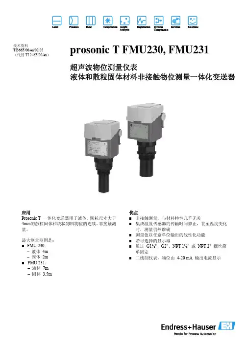
prosonic T FMU230, FMU231
超声波物位测量仪表
液体和散粒固体材料非接触物位测量一体化变送器
应用
Prosonic T 一体化变送器用于液体、颗粒尺寸大于4mm的散粒固体和块状物料物位的连续、非接触测量。
最大测量范围是:
■ FMU 230:
– 液体 4m
– 固体 2m
■ FMU 231:
– 液体 7m
– 固体 3,5m 优点
■非接触测量,与材料特性几乎无关
■集成温度传感器的传输时间修正,甚至温度变化时,测量仍然准确
■测量值以任意单位输出的线性化功能
■带可选择的显示器
■通过 G1½"、G2"、NPT 1½" 或 NPT 2" 螺丝简单固定
■二线制仪表,物位由 4-20 mA 输出电流显示
Prosonic T FMU230/FMU231
Prosonic T FMU230/FMU231
E:空罐距离;
F:满量程(满罐距离);
Prosonic T FMU230/FMU231
Prosonic T FMU230/FMU231
Prosonic T FMU230/FMU231
Prosonic T FMU230/FMU231
Prosonic T FMU230/FMU231
Prosonic T FMU230/FMU231
Prosonic T FMU230/FMU231。
光功率计使用说明书一、概述光功率计是光纤通信系统工程建設和维护中测量光电器件、光无源器件、光纤、光缆、光纤通信设备的必备工具。
二.技术条件2.1 性能指标2.基本功能a.显示方式:线性(mw/μw/ nw),对数(dBm)、相对測量(dB);b.自动功能:自动量程,自动调零,量程保持,平均处理,相对测量处理, 波长校准;三.原理光功率计由五部分组成, 即光探測器、程控放大器和程控滤波器、A/D转换器、微处理器以及控制面板与数码显示器。
被測光由PIN光探测器检测转换为光电流,由后续斩波稳定程控放大器将电流信号转换成电压信号,即实现I/V转换并放大,经程控滤波器滤除斩波附加分量及干扰信号后,送至A/D 转换器,变成相应于输入光功率电平的数字信号,由微处理器(CPU)进行数据处理,再由数码显示器显示其数据。
CPU可根据注入光功率的大小自动设置量程状态和滤波器状态,同时,可由面板输入指令(通过CPU)控制各部分完成指定工作。
不注入光的情况下,可指令仪器自动调零。
四.使用4.1 面板说明1)前面板(1)POWER 电源开关。
(2)W dBm 对数或线性测量方式转换开关按键每按一次此键,显示方式在“W”和“dBm”之间切换,并且数码显示窗右侧相应的指示器发光。
(3)d(REL) 相对测量按键。
按下,其数码显示窗右侧相应的指示器发光,可进行光功率的相对测量,参考光功率值即为按此键时的输入光功率值Pref,第二次测量的光功率显示值是相对于Pref的相对值。
按“W dBm”键便解除了此测量方式。
(4)λ SEL 波长选择键。
按一下此键,其上方指示器发光,指示仪器当前处于波长选择状态,并在数码显示窗显示其选择波长,并且右方nm指示器发光,示意单位为“纳米”。
此时,面板上其它控制键,除“MEAS”和“RMT”外,均不起作用。
(9)数码显示窗五位LED数码显示窗口。
显示光功率测量值或者(在波长选择期间)波长数。
4.2 操作电源开关置“ON”。
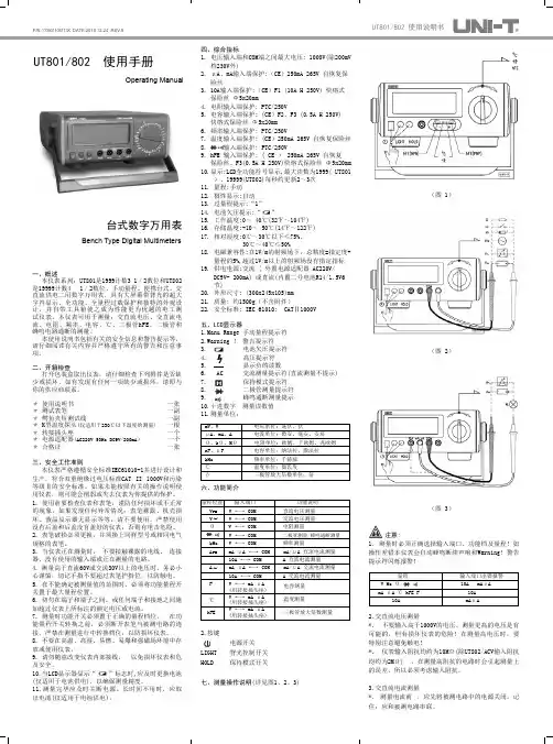
四、综合指标1. 电压输入端和COM端之间最大电压: 1000V(除200m V 档230V外)2. μA、mA输入端保护:(CE)250mA 265V 自恢复保险丝3. 10A输入端保护:(CE)F1 (10A H 250V) 快熔式保险丝 Φ5x20mm4. 电阻输入端保护: PTC/250V5. 电容输入端保护: (CE)F2、F3 (0.5A H 250V)快熔式保险丝 Φ5x20mm6. 频率输入端保护: PTC/250V7. 温度输入端保护:(CE)250mA 265V 自恢复保险丝8. 输入端保护: PTC/250V9. hFE 输入端保护: ( CE ) 250mA 265V 自恢复保险丝、F3(0.5A H250V)快熔式保险丝Φ5x20mm10.显示:LCD全功能符号显示,最大读数为1999( UT801)、19999(UT802)每秒约更新2~3次11. 量程:手动12. 极性显示:自动13. 过量程提示:“1”14. 电池欠压提示:“ ”15. 工作温度:0~ 40℃(32℉~104℉)16. 存储温度:-10~ 50℃(14℉~122℉)17. 相对湿度:0℃~30℃以下≤75%,30℃~40℃≤50%18. 电磁兼容性:在1V/m的射频场下,总精度=指定度+量程的5%,超过1V/m以上的射频场没有指定指标19. 供电电源:交流 ( 外置电源适配器 AC220V/DC9V- 200mA) 或直流(内置二号电池R14/1.5V6节)20. 外形尺寸: (300x245x105)mm21. 质量: 约1500g(不含附件)22. 安全标准: IEC 61010: CATⅡ1000V五、LCD显示器1.Manu Range 手动量程提示符2.Warning ! 警告提示符3. 电池欠压提示符4. 高压提示符5. 显示负的读数6. AC 交流测量提示符(直流测量不提示)7. 保持模式提示符8. 二极管测量提示符9. 蜂鸣通断测量提示10.+进数字 测量读数值11.测量单位:六、功能简介2.按键LIGHT 背光控制开关HOLD 保持模式开关七、测量操作说明(详见图1、2、3)UT801/802 使用说明书Operating Manual一、概述本仪表系列:UT801是1999计数31/2数位和UT802是19999计数4 1/2数位、手动量程、便携台式、交直流供电二用数字万用表。

操作手册感谢您选购本公司产品,在您使用本公司产品时,如果您发现有需要改进的地方请及时通知我们,那样有利于于我们产品设计和品质之提高。
安装A. 系统要求使用UT231接口程序,需要以下的硬件与软件要求·IBM PC或相当的80486或更高的处理器和800*600像素或更高的显示。
·WINDOWS98或以上的操作系统·8M以上内存·电脑自带CD-ROM或可以通过网络使用CD-ROM·一组空余的串行式接口·一个鼠标或其他可以被WINDOWS系统支持的点击工具B.安装UT231_232接口程序请按下面的程序安装UT231接口程序安装前请确认计算机是否在WINDOW98或以上的系统中运行1. 将本机提供的光盘放进光驱中双击桌面上我的电脑图标找到光驱的图标,然后双击图标显示UT231安装文件双击UT231安装显示文件内容双击安装.Exe 可执行文件2. 按照软件中的提示继续安装。
3. 安装完毕将出现一个UT231文件夹你可以按提示选择你需要的程序文件,你可以选择“UT231”C.使用UT231_232接口软件1. 将提供的USB接口线插入表后面的槽中,然后将线的另一端插入计算机的串行接口2. 在WINDOW的开始菜单中,选择程序〉UT231〉UT231或双击桌面上的快捷键3 按下菜单栏中的选择键开始连接,图标将会显示。
操作指南主窗口运行UT231接口程序,按以下步骤:1. 将提供的USB 接口线插入表后面的槽中,然后将线的另一端插入计算机的串行接口2. 在WINDOW 的开始菜单中,选择程序〉UT231〉UT231或双击桌面上的快捷键3.按下菜单栏中的选择键开始连接,图标将会显示。
下面是该软件在电脑上的显示(看下面的图标)主LCD 显示功能按钮区图形区图示操作(看下面的指示)在联机状态你可以点击图标或菜单栏来选择你需要的功能文件: 点击选择"填充图形" 或不点击选择"线形图形".记录:记录图形中所显示的测试数据清除:清除当前数据保存: 将当前记录用BMP格式保存默认的文件路径是C:\ TestGraph,默认的文件名是"年"+"日期"+"时间"+"页码"首页图形:第一张上一页图形:前一张下一页图形:下一张最后一页图形: 最后一张图形放大:使图表局部放大放大:左击鼠标,从上到下,从左到右拖动鼠标重建:左击鼠标,从下到上,从右到左拖动鼠标数据记录操作(看下面的指示)在联机状态你可以点击图标或菜单栏来选择你需要的功能重复记录:点击保存重复记录,或不保存忽略重复记录不论选项如何,图形窗口中都将绘制包括相同的记录的每一个数据采样间隔选项:是指用户使用软件进行较长时间采样收集数据时,可以自行设置软件每两次记录数据之间的时长,单位为秒。
UT231_232接口软件操作说明一、安装软件2.运行安装程序,并按照提示进行软件的安装。
3.安装完成后,将UT231或UT232与电脑通过RS232接口连接。
二、软件界面介绍1.串口设置:选择与UT231或UT232连接的串口,设置波特率、数据位、停止位和校验位。
2.实时数据:显示UT231或UT232当前的测量数据和状态。
3.数据记录:记录和保存UT231或UT232的测量数据。
4.曲线图:显示UT231或UT232测量数据的曲线图。
5.设置:对UT231或UT232进行相关设置,如传感器类型、阀值设置等。
三、基本使用1.打开软件后,在串口设置中选择与UT231或UT232连接的串口,并设置相应的串口参数。
2.点击“连接”按钮,与UT231或UT232建立连接。
3.在实时数据中,可以实时显示UT231或UT232当前的测量数据和状态。
4.点击“数据记录”按钮,可以记录和保存UT231或UT232的测量数据,以便后续分析和查看。
5.点击“曲线图”按钮,可以查看UT231或UT232测量数据的曲线图,便于观察数据变化趋势。
6.在“设置”中,可以对UT231或UT232进行相关设置,如传感器类型、阀值设置等。
设置完成后,点击“应用”按钮使设置生效。
四、注意事项1.在使用软件前,请确认UT231或UT232与电脑已通过RS232接口正确连接。
2.在选择串口时,请注意选择与UT231或UT232连接的串口号。
3.在进行测量时,请确保传感器连接正确,并根据实际情况选择合适的测量范围。
4.在数据记录和曲线图功能中,可以根据需要进行保存和导出数据,便于后续操作和分析。
总结:UT231_232接口软件是一款用于UT231和UT232数字型多功能表的软件,通过RS232接口与电脑连接,可以进行实时数据显示、数据记录、曲线图显示等操作。
使用软件前需要确保UT231或UT232与电脑正确连接,并根据实际情况进行相应的设置和操作。

PN 4859575 February 2017 (Simplified Chinese)©2017 Fluke Corporation. All rights reserved.Specifications are subject to change without notification. All product names are trademarks of their respective companies.Fluke CorporationP.O. Box 9090Everett, WA 98206-9090U.S.A.Fluke Europe B.V.P.O. Box 11865602 BD Eindhoven The Netherlands ООО «Флюк СИАЙЭС»125167, г. Москва, Ленинградский проспект дом 37, корпус 9, подъезд 4, 1этаж1732/1734Energy Logger安全须知访问 以注册您的产品并获取更多信息。
警告表示会对用户造成危险的状况和操作。
警告为了防止可能发生的触电、火灾或人身伤害:•在使用产品前,请先阅读所有安全须知。
•请勿改动产品并仅将产品用于指定用途,否则可能减弱产品提供的防护功能。
•遵守当地和国家的安全规范。
穿戴个人防护用品(经认可的橡胶手套、面具和阻燃衣物等),以防危险带电导体裸露时遭受电击和电弧而受伤。
•使用产品前先检查外壳。
检查是否存在裂纹或塑胶缺损。
请仔细检查端子附近的绝缘体。
•如果电源线绝缘层损坏或有磨损迹象,请更换电源线。
•进行所有测量时,请使用产品批准的测量类别 (CAT)、电压和额定电流的附件(探针、测试表笔和适配器)。
•请勿使用已损坏的测试导线。
检查测试导线是否绝缘不良,并测量已知的电压。
•如果产品被改动或已损坏,请勿使用。

UTE300系列数字功率计快速指南REV 12024.09优利德科技(中国)股份有限公司版权所有。
UNI-T 是优利德科技(中国)股份有限公司[UNI-TREND TECHNOLOGY(CHINA)CO., LTD]的注册商标。
UTE30020240907-V1.00● UNI-T 产品受中国或其他国家专利权的保护,包括已取得或正在申请的专利。
● 本公司保留更改产品规格和价格的权利。
● UNI-T 保留所有权利。
许可软件产品由UNI-T 及其子公司或提供商所有,受国家版权法及国际条约规定的保护。
本文中的信息将取代所有以前出版的资料中的信息。
本节包含着在相应安全条件下保持仪器运行必须遵守的信息和警告。
除本节中指明的安全注意事项外,您还必须遵守公认的安全程序。
交流电直流电交直流警告UTE300系列数字功率计支持测量CAT II(600V)类过压条件下的电源(UTE310H和UTE310HG支持测CAT II 1000V),请严格按照该测量环境使用仪器。
UTE300系列数字功率计包含UTE310、UTE310G、UTE310H和UTE310HG四个型号,是一款高精度高性能的数字功率计,UTE310与UTE310G的电流测量范围为25uA~20A,UTE310H与UTE310HG的电流测量范围宽至5mA~50A。
UTE300系列数字功率计适用于生产线到研发领域的功率测量。
如:●可用于DC、单相 2线的测量;●可用于空调、电磁炉等大功率家用电器的测量;●可用于显示器、打印机等办公设备的测量;●可用于LED、电源、电池等能源设备的测量;●可用于变频器、大型空调等工业设备的节能性能的评估。
2.1 功能特性UTE300系列高精度数字功率计的主要功能特性如下:●显示界面直观:使用4.3寸真彩液晶显示,读数更直观●具有示波功能:可观察信号的峰峰值和波形变化情况●基本功率参数测量:可测量电压、电流、功率、功率因数等基本功率参数,同时支持交直流信号测量;●标配谐波测量功能:支持 IEC61000-4-7 谐波测量,可分析信号中的谐波含量,如电压、电流、功率、相位角等,可显示最大 50次的谐波测量结果;●标配数学运算功能:可对测量参数进行加减乘除等运算●支持电流积分和功率积分:可积分 q、q+、q-、WP、WP+、WP-、可设置标准积分模式或循环积分模式;●通信接口丰富:用户可通过USB、RS-232/GPIB、以太网等接口远程操控仪器●具有自动量程功能:可在指定量程范围内切换到合适的量程●支持加载与访问外部存储设备:可接入U盘等外部移动存储器,长时间存储电压、电流、功率、谐波等数据,并可将仪器的配置参数导入/导出;●内置滤波器:具有线路滤波和频率滤波功能,用户可以根据需求启用线路滤波或者频率滤波来抑制基波测量时不需要的噪声和谐波成分;●具有功率计 PC 端分析软件。
目录目录 (1)概述 (2)1 技术指标 (3)2 外观 (7)3 操作方法 (8)4 附件 (34)概述UTI-1S单相标准源暨电能表校验装置采用表源一体化结构,全数字闭环标准源技术,使用嵌入式系统、大屏幕TFT彩色液晶显示器及触摸屏、CPLD芯片和高精度A/D、D/A等一系列先进器件,体积小重量轻,可广泛应用于电能计量行业、电气实验室和其他相关部门及现场使用。
它具有以下特点:• 采用触摸屏控制面板加面膜按键,显示信息量大,使用简单方便。
• 内嵌高等级标准电能表,并以此为标准进行数字闭环反馈,电压、电流、频率、相位、有功功率、无功功率、视在功率、功率因数等各参量均可作为标准使用。
• 具有多种保护功能:限流保护、功放保护、电压短路保护、电流开路保护、功放热保护等功能。
• 智能档位:在仪器允许输出的范围内,用户可以任意设定电压电流各自的额定电压、电流档位,电压电流的试验点、调节细度均参照用户设定的额定档位值,方便用户操作。
• 电流、功率因数试验点丰富,便于配置各种校表方案。
• 数据存储量大,可以很方便查询到校验数据。
• 带有RS232串口,便于计算机控制及升级软件。
1技术指标1.1电源输出:1.1.1交流电压输出调节细度:0.01%R G分辨率:6位有效数字准确度:优于±0.1%R G稳定度:优于±0.01%R G/1m i n失真度:优于 0.3%(非容性负载)输出功率:额定 20V A满负载调整率:小于±0.01%R G输出范围:10V~456V档位设置:57.7V、100V、220V、380V,内部自动档位切换 。
1.1.2交流电流输出调节细度:0.01%R G准确度:优于±0.1%R G分辨率:6位有效数字稳定度:优于±0.01%R G/1m i n失真度:优于 0.3%输出功率:档位额定输出20V A,100A档额定输出50V A。
满负载调整率:小于±0.01%R G输出范围: 0.5m A~ 24(120)A档位设置: 0.2A、1A、5A、20(120)A,自动档位切换。
UTE300系列数字功率计用户手册版本:REV.1日期:2024.08.30目录前言 (6)版权信息 (6)保固服务 (6)保证限制 (6)第一章安全须知 (7)1.1安全信息 (7)1.2使用环境条件 (9)第二章验货与安装 (10)2.1 包装清单检查 (10)2.2 手柄调节 (13)第三章产品介绍 (13)3.1 产品概述 (13)3.2 功能特性 (14)3.3 应用系统 (15)3.4 技术规格 (16)3.5 前面板介绍 (19)3.5.1 前板按键功能介绍 (19)3.5.2 按键组合功能介绍 (21)3.5.3 显示屏显示的内容及表示功能 (21)3.6 后面板介绍 (22)第四章操作准备与线路连接 (24)4.1 操作前准备 (24)4.1.1 确定仪器供电电源 (24)4.2 线路连接 (24)4.2.1 直接输入电压和电流的线路连接(○1) (25)4.2.2 直接输入电压与CT输入电流的线路连接(○2) (26)4.2.3 直接输入电压与EXT输入电流的线路连接(○3) (26)4.2.4 直接输入电压与(CT+EXT)输入电流的线路连接(○4) (27)4.2.5 VT输入电压与直接输入电流的线路连接(○5) (28)4.2.6 VT输入电压与CT输入电流的线路连接(○6) (28)4.2.7 VT输入电压与EXT输入电流的线路连接(○7) (29)4.2.8 VT输入电压与(CT+EXT)输入电流的线路连接(○8) (29)4.2.9 仪器供电连接 (30)第五章测量设置 (31)5.1 量程设置 (31)5.1.1 电压量程设置 (31)5.1.2 电流量程设置 (31)5.1.3 量程切换 (32)5.2 测量模式设置 (33)5.3 测量菜单及设置 (33)5.3.1 页面-1介绍及设置 (34)5.3.2 页面-2介绍及设置 (35)5.3.3 页面-3介绍及设置 (35)5.4 谐波测量 (36)5.4.1 柱状图显示谐波 (37)5.4.2 列表显示谐波 (37)5.4.3 谐波设置 (38)5.5 波形显示 (39)5.5.1 显示时间轴 (39)5.5.2 显示垂直轴 (39)5.6 积分 (40)5.6.1 标准积分 (40)5.6.2 循环积分 (41)5.6.3 积分模式对比 (42)5.6.4 积分的方法 (43)5.6.5 积分设置 (43)5.6.6 积分操作 (44)5.6.7 积分时的操作限制 (45)第六章功能设置 (46)6.1 设置 (46)6.1.1 同步源 (47)6.1.2 线路滤波器 (49)6.1.3 频率滤波器 (49)6.1.6 自动更新时间 (50)6.1.7 自动更新同步源 (51)6.1.8 恢复出厂设置 (51)6.2 平均滤波 (52)6.2.1 平均状态 (52)6.2.2 平均类型 (52)6.2.3 平均次数 (53)6.3 传感器 (53)6.3.1 选择外部电流传感器通道 (53)6.3.2 传感器通道1系数(mV/A) (53)6.3.3 传感器通道2系数(mV/A) (54)6.3.4 应用举例 (54)6.4 变比 (54)6.4.1 变比状态 (55)6.4.2 比例设置 (55)6.4.3 应用举例 (55)6.5 跳跃 (56)6.5.1 跳跃配置 (57)6.5.2 峰值跳跃 (57)6.5.3 应用举例 (57)6.6 D/A输出与控制 (57)6.6.1 格式 (58)6.6.2 量程模式 (58)6.6.3 远程控制信号 (60)6.6.4 接口引脚定义 (61)第七章系统 (62)7.1 系统信息 (62)7.2 系统设置 (63)7.2.1 背光亮度 (63)7.2.2 按键声音 (63)7.2.5 系统语言 (64)7.2.6 存储间隔 (64)7.2.7 系统时间 (65)7.3 串口 (65)7.3.1通信波特率 (66)7.4 GPIB设置 (66)7.5 网络 (66)7.5.1 IP模式 (67)7.5.2 IP地址 (67)7.5.3 子网掩码 (67)7.5.4 网关 (67)7.6 U盘 (67)第八章通信接口 (67)8.1 RS-232接口 (67)8.1.1 RS-232接口设置流程 (68)8.1.2 PC通过RS-232接口与功率计连接 (68)8.2 以太网接口 (69)8.2.1 网络设置流程 (69)8.2.2 PC通过以太网接口与功率计连接 (69)8.3 USB 接口 (70)8.3.1 PC通过USB接口与功率计连接 (70)8.4 GPIB接口(选配) (71)8.4.4 PC通过GPIB接口与功率计连接 (71)第九章存放与校准 (73)9.1 存放注意事项 (73)9.2 常见故障及排除 (73)9.3 校准注意事项 (73)第十章保险丝更换 (75)附录一测量功能的符号和求法 (76)附录二测量精度和测量误差 (77)前言感谢您购置优利德数字功率计,为了确保正确使用本仪器,在操作仪器之前请仔细阅读手册,特别是有关“安全事项”部分。
ELE-WI
xxx有限公司
仪器设备名称: 数字功率计
工作电源: 220V / 50HZ
操作步骤:
1.先将电源线插头插入220V / 50HZ的带电插座;
2.首先打开数字功率计前面板右下角的电源开关,可以看到叁个数字显示窗口,第一排从左到右,窗口A显示电压V;窗口B显示电流A;第二排的窗口C根据需要按“功能转换键”
可以选择显示功率因数PF或频率Hz;
3.设置有效电流上下限值:在操作区内按设定键,当窗口A显示“AMP”表示设定电流的上下限值,其中超上限指示灯亮时表示设定电流的上限值,超下限指示灯亮时表示设定电流下限值,窗口C显示要设定的电流上下限值;电流上下限值设定范围为:0.000A~9999A;4.置有效功率上下限值:在操作区内按设定键,当窗口A显示“POW”表示设定功率的上下限值,其中超上限指示灯亮时表示设定功率的上限值,超下限指示灯亮时表示设定功率下限值,窗口C显示要设定的功率上下限值;功率上下限值设定范围为:0.0000W~99999W;5.相关键:设定键、“∧”表示光标处数值循环加一、“>”表示光标循环右移、“·”表示小数点循环右移;
6.在仪器后面有四个接线柱,分别是输入和输出电源的接线柱,将输入电源接在输入的接线柱上,将输出电源接在输出的接线柱上;
7.测试:将被测工件的电源与功率计的输出电源连接,并启动被测工件,在叁个窗口分别读出该工件的相应参数;
8.要求在下班和长时间离开时关掉本仪器的电源,并经常保养清洁。
第 1 页共1 页。
UT33A+万用表说明书1. 安全注意事项1)后盖没有盖好前严禁使用,否则有点击危险。
2)使用前确认仪表和表笔绝缘层完好,无破损及短线。
3)在使用时,用户手指必须放在表笔手指保护环之后。
4)不要测量高于600V以上电压5)直流电压高于60V,或者交流电压高于30Vrms,应小心谨慎,防止触电。
6)严禁在测量中拨动量程开关档位,防止损坏仪器。
7)必须使用同类标称的快速反应保险丝,更换已损坏的保险管。
2. 综合规范1)输入端子和接地之间最高电压:600Vrms2)10A端子设:Fuse 10A H 250V 快熔式保险丝:Φ5 * 20mm3)mA/µA端子设:Fuse 200mA(0.2A)H 250V 快熔式保险丝:Φ5 * 20mm 3. 外表结构1)SEL/REL按键:点击可以循环切换交流/直流mV量程,交流/直流电流量程,电容档相对测量量程。
每点击一次,对应的测试功能档量程交替切换(仅适用档位:mV,I,REL)2)HOLD/¤按键:点击进入数据保持/取消数据保持模式;长按大于2s,可以打开/关闭背光。
4. 量程操作说明屏幕上显示,更换电池再使用。
,这是警示你,要留意被测试的电压或电流不要超出指示数字,以确保测量安全。
1)直流电压与交流电压测量(见图2b)①将量程开关拨到交流电压档位上②将红表笔插入“VΩmA"插孔,黑表笔插入“COM"孔,并将两只表笔笔尖分别接触所测电压两端(并联到负载上)进行测量;2)电阻测量(见图2b)①将量程开关拨到电阻测量档位上②将红表笔插入“VΩmA"插孔,黑表笔插入“COM"孔,并将两只表笔笔尖分别接触所测电阻的两端,与被测电阻并联进行测量。
注意:①将当在线测量式,为避免一起损坏和伤及用户,在测量前必须将被测电路内所有电源关断,并将所有电容器上的残余电荷放尽。
②如果表笔短路时电阻值不小于0.5Ω时,应检查表笔是否有松脱或者其它异常。
UT231_232接口软件操作说明一、接口软件简介二、安装和运行软件2.安装完成后,点击桌面上的UT231/232接口软件图标,打开软件。
三、软件界面及功能1.主界面工具栏包含快速打开、保存和刷新等功能按钮,用户可通过工具栏进行快捷操作;连接状态显示当前仪器的连接状态,方便用户实时监测仪器连接情况;数据显示窗口显示仪器中的数据,并提供数据导出功能,用户可以将数据保存到本地。
2.仪器连接在菜单栏中,选择工具->连接仪器,弹出连接设置对话框。
用户在对话框中选择串口或USB端口,并点击连接按钮进行连接。
连接成功后,连接状态将显示为“已连接”。
3.数据传输在连接成功后,用户可以选择工具->传输数据来传输仪器中的数据。
在传输数据对话框中,用户可以选择传输的时间范围,点击传输按钮进行数据传输。
传输完成后,数据将显示在数据显示窗口中。
4.数据分析用户可以通过菜单栏中的查看->绘制曲线图,绘制仪器中的数据曲线图。
在绘制曲线图对话框中,用户可以选择要绘制的数据项和时间范围,点击绘制按钮即可绘制曲线图。
5.数据保存用户可以通过菜单栏中的文件->保存数据,将数据保存到本地。
在保存数据对话框中,用户可以选择保存的文件格式和保存的路径,点击保存按钮即可保存数据。
6.数据导出用户可以通过菜单栏中的文件->导出数据,将数据导出为Excel、CSV或文本文件等格式。
在导出数据对话框中,用户可以选择导出的文件格式和导出的路径,点击导出按钮即可导出数据。
7.软件设置用户可以通过菜单栏中的工具->设置,进行软件相关的设置。
在设置对话框中,用户可以设置数据显示的单位、曲线图的尺寸、数据的时间格式等。
四、常见问题解决方法1.仪器连接不上a.检查仪器是否正确连接到计算机的串口或USB端口;b.检查连接设置是否正确,包括选择的端口号和波特率等参数是否与仪器设置一致;c.检查仪器的电源供应是否正常。
2.数据传输不成功a.确保仪器已连接成功,连接状态显示为“已连接”;b.检查传输设置是否正确,包括选择的时间范围是否正确;c.尝试重新传输数据,或者重新连接仪器后再进行传输。
UT使用说明书目录项目页一、概述二、开箱检查三、安全操作准则四、电气符号五、外表结构六、显示符号七、按键功能及自动关机八、测量操作说明1.直流电压测量2.交流电压测量3.电阻测量4.二极管测量5.导通检测6.频率测量7.占空比测量8.直流电流测量9.交流电流测量3 3 4 6 7 8 9 11 11 12 13 14 15 16 17 18 1912项目页九、技术指标 1.一般规格 2.环境限制 3.电气规格 (1)直流电压 (2)交流电压 (3)电阻 (4)二极管测试 (5)导通测试 (6)频率 (7)占空比 (8)直流电流 (9)交流电流十、保养和维护 1.一般维护 2.电池安装或更换 20202121222224242525262627292929一、概述UT203、UT204是一种性能稳定,安全、可靠的3 3/4位交直流数字钳形表(以下简称钳表)系列。
整机电路设计以大规模集成电路双积分A/D转换器为核心,全量程的过载保护电路,独特的外观设计使之成为性能优越的专用电工仪表。
钳表可用于测量交直流电压、交直流电流、电阻、二极管、电路通断、频率等。
本使用说明书包括有关的安全信息和警告提示等,请仔细阅读有关内容并严格遵守所有的警告和注意事项。
警告在使用钳表之前,请仔细阅读有关“安全操作准则”二、开箱检查打开包装盒,取出仪表,请仔细检查下列项目是否缺少或损坏:1.使用说明书2.表笔3.带夹短测试线4.布包5.保用证一本一付一付一只一张如果发现任何一个项目缺少或损坏,请立即与您的供应商进行联系。
3三、安全操作准则请注意“警告标识及警告字句”。
警告表示对使用者构成危险、对仪表或被测设备可能造成损坏的情况或行动。
使用前应检查钳表和表笔,谨防任何损坏或不正常的现象。
如发现本钳表表笔、壳体绝缘已明显损坏以及液晶显示器无显示等,或者您认为本钳表已无法正常工作,请勿再使用本钳表。
后盖及电池盖没有盖好前严禁使用钳表,否则有电击危险。