SMC AFM20-40 油雾分离器
- 格式:pdf
- 大小:297.99 KB
- 文档页数:3
af4000-04过滤器说明书
1.AF4000-04单联件油水分离气源处理器型号含义:
AF4000-04是SMC型空气过滤器,4000表示外形的尺寸大小,-04表示它的接管口径是PT1/2,4000系列有杯防护罩。
2.共同规格:
① 保证耐压力:1.5Mpa{15.3kgf/cm}
② 高使用压力:1.0Mpa{10.2kgf/cm}
③ 环境及流体温度:5~60°C
④ 过滤孔径:5um
⑤ 杯材质:PC
⑥ 杯防护罩:无
⑦ 调压范围:0.05~0.85Mpa{0.51~8.7kgf/cm}
3.气源处理件的选择及使用要求:
① 根据管路通径、流量大小、调压及过滤精度等技术性能等参数选择系统所
需要的空气组合件;
② 空气过滤器的过滤精度有2um、5um、10um、20um、40um、70um、100um七种,可根据空气的质量要求选用合适的产品;
③ 在使用减压阀时,尽量避免使用调压范围的下限值,按使用压力的要求选
择合适的减压阀;
④ 安装顺序:从气源的流入端开始,一次连接空气过滤器、减压阀、油雾器,元件壳体上的箭头方向为气流方向,不可反接;
⑤ 空气过滤、油雾器必须竖直安装并使带有罩杯侧朝下;
⑥ 油雾器一旦逆流,就会造成内部零件损坏和发生危险,故应避免发生;
⑦ 安装连接时,避免将密封胶带、铁锈等杂质混入管路内。
编辑本段气源处
理件的使用及维护。
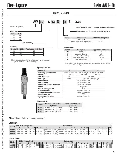
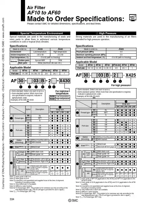
Series AW20~40Filter -RegulatorHow To OrderAW 30N 03D8Z -X48——Filter -Regulator Note:Other sizes,thread forms,options,etc.may be possible,please contact SMC for availability.With External Epoxy Coating,Stainless Fasteners Name Plate,Caution Plate On Bowl in psi,˚FNPT ThreadsBody SizeSymbol 203040Size 1/83/81/2Port SizeSymbol 020304Port Size 1/43/81/2Applicable Body Size203040SpecificationsBody sizeOperating specifications Port sizeAuto drain port Bowl type Body material Bowl materialBody,Bowl surface treatment BonnetManual drain (AF ,AW)External screwsIndividual mounting brackets Panel mount nutSight glass hardware203040Same as standard -see catalog ES40-42D or NC160A1/4”NPT N/A Metal 1/4”NPT Metal with sight gaugeDie cast aluminum Die cast aluminum Epoxy resin coatingPolyacetal POMStainless steel 410Epoxy coated steelPOMStainless steel 3043/8”NPT1/2”NPT BowlSymbol 28DescriptionMetal BowlMetal Bowl With Sight GlassApplicable Body Size 2030,40Accessories Symbol Nil B*C D H*Description None Mounting Bracket Float Auto Drain (N.C.)Float Auto Drain (N.O.)Panel Mount NutApplicable Body SizeAll All 30,4030,40AllAW30AW40A NPT 3/8NPT 1/2Dimensions Model Port Size C NPT 1/8NPT 1/4Gauge PortD 5370DD 34.541E 3038F 83(max.86)88(max.92)H3.51.5J 239(max.242)276(max.280)K 5975L 4150Q 4654S 6.58.5U 4054T 810.5V 5370W 2.32.3X M38X 1.5M42X 1.5Y 3135.5Z 77AA 1921CC 38.542.5AW20AW30AW40A NPT 1/4NPT 3/8NPT 1/2Dimensions Model Port Size C NPT 1/8NPT 1/8NPT 1/4Gauge PortD405370DD —34.541E —3038F 70(max.73)83(max.86)88(max.92)H 53.51.5J 157(max.160)218(max.221)255(max.259)K 525975L 304150Q 444654S 5.46.58.5U 344054T 15.4810.5AW20AW30AW40Mounting Bracket Kit(Optional)AW20P-270AS-X480AR30P-270AS-X480AR40P-270AS-X480Model V 555370W 2.32.32.3X M28X 1M38X 1.5M42X 1.5Y 303135.5Z 677AA 141921CC 28.538.542.5Panel Mounting Nut(Optional)AR20P-260S AR30P-260S AR40P-260SAuto DrainStandardAccessoriesDimensions -Refer to drawings on page 7mmmm *Note:Bracket and/or panel mount nut are not assembled and are suppliedloose at time of shipment.C o u r t e s y o f C M A /F l o d y n e /H y d r a d y n e ▪ M o t i o n C o n t r o l ▪ H y d r a u l i c ▪ P n e u m a t i c ▪ E l e c t r i c a l ▪ M e c h a n i c a l ▪ (800) 426-5480 ▪ w w w .c m a f h .c o mSeries AW20~40Filter -RegulatorStandard(ManualDrain)2-Bracket and (Optional )With AutoDrain2-Bracket and (Optional)Bowl Detail EE(AW20)Note:Sight glass not applicable to AW20.C o u r t e s y o f C M A /F l o d y n e /H y d r a d y n e ▪ M o t i o n C o n t r o l ▪ H y d r a u l i c ▪ P n e u m a t i c ▪ E l e c t r i c a l ▪ M e c h a n i c a l ▪ (800) 426-5480 ▪ w w w .c m a f h .c o m。
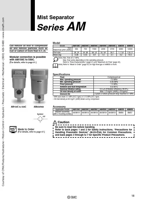
AM150C to 550C AM650/850Mist SeparatorSeries AMCan remove oil mist in compressed air and remove particles such as rust or carbon of more than 0.3 μm.Note) Max. flow at 0.7 MPa.Max. flow varies depending on the operating pressure.Refer to “Flow Characteristics” (page 21) and “Maximum Air Flow” (page 22).Note) Refer to “Made to Order” (page 67) for high flow type of AM850 or more.Specifications0.05 MPa 1.5 MPa FluidMax. operating pressure Min. operating pressure ∗Proof pressureAmbient and fluid temperature Nominal filtration rating Element lifeCompressed air1.0 MPa 5 to 60°C0.3 μm (Filtration efficiency: 99.9%)Oil mist density at outlet Max. 1.0 mg/m 3 (ANR) (≈0.8 ppm)∗2 years or when pressure drop reached 0.1 MPa∗ With auto drain: 0.1 MPa (N.O. type) or 0.15 MPa (N.C. type)∗ Oil mist density at 30 mg/m 3 (ANR) blown out by compressor.SymbolAMModular connection is possible with AM150C to 550C.(For details, refer to page 61.)Made to Order(For details, refer to page 67.)CautionBe sure to read this before handling.Refer to back pages 1 and 2 for Safety Instructions, “Precautions for Handling Pneumatic Devices” (M-03-E3A) for Common Precautions, and back pages 3 through to 7 for Specific Product Precautions.o u r t e s y o f C M A /F l o d y n e /H y d r a d y n e ▪ M o t i o n C o n t r o l ▪ H y d r a u l i c ▪ P n e u m a t i c ▪ E l e c t r i c a l ▪ M e c h a n i c a l ▪ (800) 426-5480 ▪ w w w .c m a f h .c o mHow to OrderOptionsCombinations”.Series AMo u r t e s y o f C M A /F l o d y n e /H y d r a d y n e ▪ M o t i o n C o n t r o l ▪ H y d r a u l i c ▪ P n e u m a t i c ▪ E l e c t r i c a l ▪ M e c h a n i c a l ▪ (800) 426-5480 ▪ w w w .c m a f h .c o mHow to OrderAuto Drain Specifications/Option Combinations∗2∗2 Refer to “Auto Drain Specifications/OptionCombinations”.∗3Body size 850 is equipped with a ball valve(Rc3/8 female threaded). Mount a pipingadapter IDF-AP609 (page 62) to the ball valve if NPT3/8 female threaded is required.∗4Drain piping and piping for a stop valvesuch as ball valve are required.: Available Mist Separator SeriesAMo u r t e s y o f C M A /F l o d y n e /H y d r a d y n e ▪ M o t i o n C o n t r o l ▪ H y d r a u l i c ▪ P n e u m a t i c ▪ E l e c t r i c a l ▪ M e c h a n i c a l ▪ (800) 426-5480 ▪ w w w .c m a f h .c o mAM150C AM250C AM550CAM350C AM450CAM850AM650Note) Compressed air over max. flow line in the table below may not meet the specifications of the product.It may cause damage to the element.Flow Characteristics (Element oil saturation)P r e s s u r e d r o p (M P a )Air flow rate (l /min (ANR))P r e s s u r e d r o p (M P a )Air flow rate (l /min (ANR))P r e s s u r e d r o p (M P a )Air flow rate (l /min (ANR))P r e s s u r e d r o p (M P a )Air flow rate (l /min (ANR))P r e s s u r e d r o p (M P a )Air flow rate (l /min (ANR))P r e s s u r e d r o p (M P a )Air flow rate (l /min (ANR))P r e s s u r e d r o p (M P a )Air flow rate (m 3/min (ANR))Max. flow lineMax. flow lineMax. flow lineMax. flow lineMax. flow lineMax. flow lineMax. flow lineSeries AMo u r t e s y o f C M A /F l o d y n e /H y d r a d y n e ▪ M o t i o n C o n t r o l ▪ H y d r a u l i c ▪ P n e u m a t i c ▪ E l e c t r i c a l ▪ M e c h a n i c a l ▪ (800) 426-5480 ▪ w w w .c m a f h .c o mAM150C to 550C, AM650AM850ConstructionMaximum Air FlowMax. flow lineModel SelectionM a x . a i r f l o w r a t e (m 3/m i n (A N R ))Select a model in accordance with the following procedure taking the inlet pressure and the max. air flow rate into consideration.(Example) Inlet pressure: 0.6 MPaMax. air flow rate: 5 m 3/min (ANR)1.Obtain the intersecting point A of inlet pressure and max. air flow rate in the graph.2. The AM650 is obtained when the max. flow line is above the inter-secting point A in the graph.Note) Sight glass is indicated in the figure for easy understanding ofcomponent parts. However, it differs from the actualconstruction. Refer to dimensions on pages 23 through to 25 for details.∗ Element assembly: With gasket (1 pc.) and O-ring (1 pc.)∗ Refer to back page 6 for replacement of auto drain.∗ Element assemblies for Made to Order (X6, X12, X15, X17, X20, X26, X37) are same as those for standard (see the above table).Note)Make sure to select a model that has the max. flow line abovethe obtained intersecting point. With a model that has the max. flow line below the obtained intersecting point, the flow rate will be exceeded, thus leading to a problem such as being unable to satisfy the specifications.OUTIN Mist Separator SeriesAMo u r t e s y o f C M A /F l o d y n e /H y d r a d y n e ▪ M o t i o n C o n t r o l ▪ H y d r a u l i c ▪ P n e u m a t i c ▪ E l e c t r i c a l ▪ M e c h a n i c a l ▪ (800) 426-5480 ▪ w w w .c m a f h .c o mDimensionsAM150C to 550CC: With auto drain (N.C.)D: With auto drain (N.O.)OptionJ: Drain guide 1/4 female threadedCombination of D: With auto drain (N.O.) S, U: With differential pressure switch (with indicator)T: With element service indicatorSeries AMo u r t e s y o f C M A /F l o d y n e /H y d r a d y n e ▪ M o t i o n C o n t r o l ▪ H y d r a u l i c ▪ P n e u m a t i c ▪ E l e c t r i c a l ▪ M e c h a n i c a l ▪ (800) 426-5480 ▪ w w w .c m a f h .c o m1807085324.5121361601601502025315401133410311205537M a i n t e n a n c e s p a c eDrainDimensionsAM650T: With element service indicatorAuto drainD: With auto drain (N.O.)OptionJ: Drain guide 1/4 female threaded201/4 female threaded34Drain cock: Blackø10 one-touch fitting(Accessory)Bracket Mist Separator SeriesAMOUTINOUTINo u r t e s y o f C M A /F l o d y n e /H y d r a d y n e ▪ M o t i o n C o n t r o l ▪ H y d r a u l i c ▪ P n e u m a t i c ▪ E l e c t r i c a l ▪ M e c h a n i c a l ▪ (800) 426-5480 ▪ w w w .c m a f h .c o m22011022018024120424615861818422015133034846410Rc 3/8 female threadedM a i n t e n a n c e s p a c e Bracket (Accessory)DimensionsAM850Auto drainD: With auto drain (N.O.)for AM850OptionT: With element service indicator233/8 female threadedSeries AMDrainOUTIN OUTIN o u r t e s y o f C M A /F l o d y n e /H y d r a d y n e ▪ M o t i o n C o n t r o l ▪ H y d r a u l i c ▪ P n e u m a t i c ▪ E l e c t r i c a l ▪ M e c h a n i c a l ▪ (800) 426-5480 ▪ w w w .c m a f h .c o m。
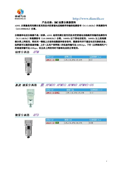
产品名称:SMC油雾分离器资料
ADSL分离器是利用频分复用的技术把普通电话线路所传输的低频信号(0.3-3.4KHz)和高频信号(4.0-1000KHz)分离。
分离器和电话分线器不是一回事。
ADSL是利用频分复用的技术把普通电话线路所传输的低频信号(0.3-3.4KHz)和高频信号(4.0-1000KHz)分离。
3400Hz以下供电话使用;3400Hz以上的高频部分供上网使用,即在同一铜线上分别传送数据和语音信号,数据信号并不通过电话交换机设备。
这样就可以提供高速传输:上行(从用户到网络)的低速传输可达640Kbps,下行(从网络到用户)的高速传输可达6Mbps;而且在上网的同时不影响电话的正常使用。
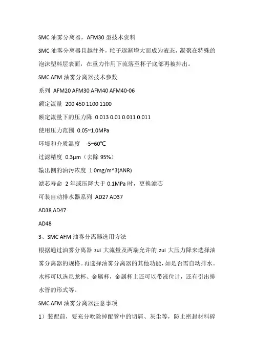
SMC油雾分离器,AFM30型技术资料SMC油雾分离器且越往外,粒子逐渐增大而成为液态,凝聚在特殊的泡沫塑料层表面,在重力作用下流落至杯子底部再被排出。
SMC AFM油雾分离器技术参数系列AFM20 AFM30 AFM40 AFM40-06额定流量200 450 1100 1100额定流量下的压力降0.013 0.01 0.011 0.011使用压力范围0.05~1.0MPa环境和介质温度-5~60℃过滤精度0.3μm(去除95%)输出侧的油污浓度1.0mg/m^3(ANR)滤芯寿命2年或压降大于0.1MPa时,更换滤芯可装自动排水器系列AD27 AD37AD38 AD47AD483、SMC AFM油雾分离器选用方法根据通过油雾分离器zui大流量及两端允许的zui大压力降来选择油雾分离器的规格。
再选择油雾分离器的其他功能,如是否需自动排水。
水杯可以选尼龙杯、金属杯,金属杯上还可以带液位计,还有引出排水管的形式等。
SMC AFM油雾分离器注意事项1)装配前,要充分吹除掉配管中的切屑、灰尘等,防止密封材料碎片混入。
2)进出口方向不得装反,要垂直安装,水杯向下。
3)不得安装在接近空压机处。
应安装在用气装置的附近。
4)定期排水,水位不得超过挡水板。
5)滤芯要定期清洗或更换。
清洗滤芯要用中性清洗剂。
6)在AFM前面应安装AF,以提高AFM寿命。
7)使用流量不要超过额定流量,否则已凝聚的油滴会被气流从滤芯表面上撕下来流向出口侧,不能充分发挥油雾分离器的性能。
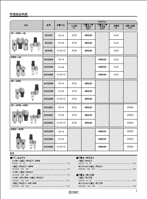
新款模块式F.R.L.空气组合元件新AC20 AC25 AC30 AC40组合构成元件系列/CAD 接管口径设定压力(MPa)空气过滤器/减压阀/油雾器AF+AR+AL【新】1/8,1/4,3/8,1/2,3/4 0.05~0.7过滤减压阀/油雾器AW+AL【新】1/8,1/4,3/8,1/2,3/4 0.05~0.7空气过滤器/减压阀AF+AR【新】1/8,1/4,3/8,1/2,3/4 0.05~0.7空气过滤器/油雾分离器/减压阀AF+AFM+AR【新】1/8,1/4,3/8,1/2,3/4 0.05~0.7过滤减压阀/油雾分离器AW+AFM【新】 1/8,1/4,3/8,1/2,3/4 0.05~0.7空气过滤器AF系列/CAD 接管口径过滤精度(μm)AF10~60 M5×0.81/8,1/4,3/8,1/2,3/4,1 5新款空气过滤器新AF20 AF30 AF40系列/CAD 接管口径过滤精度(μm)AF20~40【新】1/8,1/4,3/8,1/2,3/4 5 油雾分离器AFM系列/CAD 接管口径过滤精度(μm) AFM20~40 1/8,1/4,3/8,1/2,3/4 0.3。
油雾分离器(吸雾器)简述:在现代的数控机床加工过程中,一般工业用切削油或冷液经过加工受热、气化后,会产生大量的浮游雾状物,这些油气与雾气均含有多氯联苯成分,易造成有毒雾气,严重地伤害到工作人员的健康。
为避免有毒油气长时间的扩散,创造舒适工作环境,延长机床设备寿命和提升生产效率,现代大多的数控机床都配备了相应的油雾吸除装置瑞浩科技公司长期致力于研发和制造领先的工业机床用吸雾器、集尘器以及相关环境保护设备。
凭借当前最新的设计理念和与尖端的制造科技,不断推陈出新地为机床制造行业提供高端环保机器以及相应解决之道。
瑞浩科技公司的吸雾器根据工作原理分为,离心式、静电式和集中式三个大类。
每个型号更配有不同的吸雾量和吸雾孔口径。
瑞浩科技公司的RH系列吸雾器拥有:吸雾彻底、效果明显、无抖动、无噪音、服务完善、品种齐全等优点。
RH离心式吸雾器工作原理:RH系列离心式吸雾器应用离心分离及高效过滤技术,油雾废气在引力的作用下吸入机床油雾清洁器,首先在经匀风器匀风,进入第一级过滤装置,去除20um以上的油雾颗粒,之后进入离心分离系统,在高速旋转的叶轮的作用下产生强大的离心力,使用3um以上的油雾颗粒从废气中分离出来并回流到积油盘中,最后进入高效过滤器,滤掉0.3um级的油雾小颗粒。
经过CRD系列油雾烟气过滤器处理后,油雾烟气能有效地被捕抓收集,收集效率达99%以上,是目前机械加工行业油雾废气处理回收较为理想的设备。
应用范围ApplicationsRH油雾清洁器应用于切削油、柴油及冷却液加工时产生的油雾及水溶性雾气。
例如:此设备适用于CNC综合铣床、CNC数控机床、清洗机、外圆、平面磨床、滚齿、铣床和插齿机床、真空泵、喷雾试验室、电火花加工、数控加工中心。
等会产生油气的设备,及密闭式作业空间的水气油雾回收处理。
尤其适用于轴承制造行业,全封闭机床(特别是磨床)、封闭式空调恒温车间。
产品特点Features·油雾收集率高,对雾状物的捕尘效率真达到98%·维护简单方便,采用插入式安装。
────────────────────────────使用说明书────────────────────────────高分子膜式空气干燥器IDG30・IDG30H・IDG30LIDG50・IDG50H・IDG50L高分子膜式空气干燥器(M型)IDG30M・IDG30HM・IDG30LM IDG50M・IDG50HM・IDG50LM高分子膜式空气干燥器(V型)IDG30V・IDG30HV・IDG30LV IDG50V・IDG50HV・IDG50LV非常感谢您购买SMC公司生产的高分子膜式空气干燥器(单元)。
请认真阅读产品使用说明书,正确使用该产品。
请妥善保管产品使用说明书。
在产品的使用过程中出现故障或不知应用时,请仔细查阅产品使用说明书。
目录1. 注意事项1-1 使用注意事项 ・・・・・・・・・・・・・・・・・・ 11-2 安装注意事项 ・・・・・・・・・・・・・・・・・・ 22. 维护和保养2-1 每天进行的维护 ・・・・・・・・・・・・・・・・ 32-2 每月一次的维护 ・・・・・・・・・・・・・・・・ 32-3 两年一次的保养 ・・・・・・・・・・・・・・・・ 32-4 四年一次的保养 ・・・・・・・・・・・・・・・・ 33. 更换零件3-1 高分子膜相关零件的更换方法 ・・・・ 43-2 自动排水器的清洗方法 ・・・・・・・・・・ 53-3 滤芯的更换方法 ・・・・・・・・・・・・・・・・ 53-4 更换零件一览表 ・・・・・・・・・・・・・・・・ 64. 外形尺寸和各零件名称 ・・・・・・・・・・・・・・・・・・75. 规格 ・・・・・・・・・・・・・・・・・・・・・・・・・・・・・・96. 申请服务之前 ・・・・・・・・・・・・・・・・・・・・・・・・・・ 10安全注意事项产品有本身的规格。
如果在规格范围外使用,可能会造成意外的故障。
请按照使用说明中的注意事项,在确认产品规格的基础上,正确使用。
AM150C ~550CAM650, 850油雾分离器AM 系列能分离并除去油雾和0.3µm 以上的锈末、碳粒等固态粒子。
注)AM850以上的大流量型参见P.67订制规格。
※带自动排水起为0.1MPa(N.O.型)、0.15MPa(N.C.型)∗空压机输出油雾浓度为30mg/m 3(ANR)时注意使用前必读。
安全上的注意由后附1、2、压缩空气清净化元件/共同注意事项(M-C03-3)、产品单独注意事项由后附3~7确认。
图形符号AM订制规格(详细参见P.67。
)AM150C~550C 可模块化连接。
(详细参见P.61。
)型号表示方法可选项说明AM150C ~AM550CAM 系列自动排水器规格及可选项的组合表)器身组件的型号表示方法参见P.63。
型号表示方法AM650, 850※2自动排水器规格和可选项的组合参见下表。
※3主体尺寸850带球阀(Rc3/8内螺纹)。
NPT3/8内螺纹必要的场合,请另行将配管联接器IDF-AP609(参见P.62)安装在球阀上。
○:可组合不可组合油雾分离器AM 系列压力降空气流量最大流量线压力降空气流量最大流量线压力降空气流量最大流量线压力降空气流量最大流量线压力降空气流量最大流量线压力降空气流量最大流量线压力降空气流量最大流量线AM150C AM250C AM550CAM350C AM450CAM850AM650AM 系列AM150C ~AM550C, AM650AM850构造图最大流量线图最大流量线型号的选定方法根据进口压力及最大空气流量按下列步骤选定型号。
(例)进口压力 :0.6MPa最大空气流量 :5m 3/min(ANR)q 利用「最大流量线图」,求进口压力和最大空气流量的交点A 。
w 按最大流量线在交点A 之上来选定型号。
本例应选AM650。
)器身组件的型号表示方法参见P63。
注)本构造图是示意图,实际观察窗的安装位置可能与图示位置不一致。
详细外形尺寸参见P.23~25。