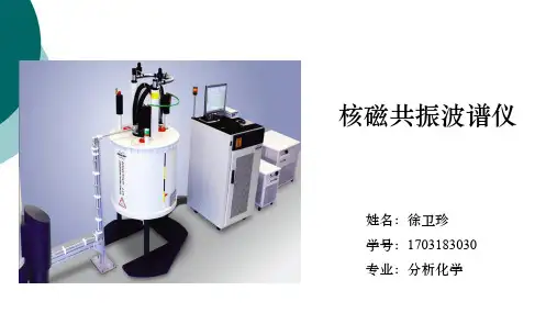
NMR仪器介绍2
- 格式:ppt
- 大小:1.64 MB
- 文档页数:26


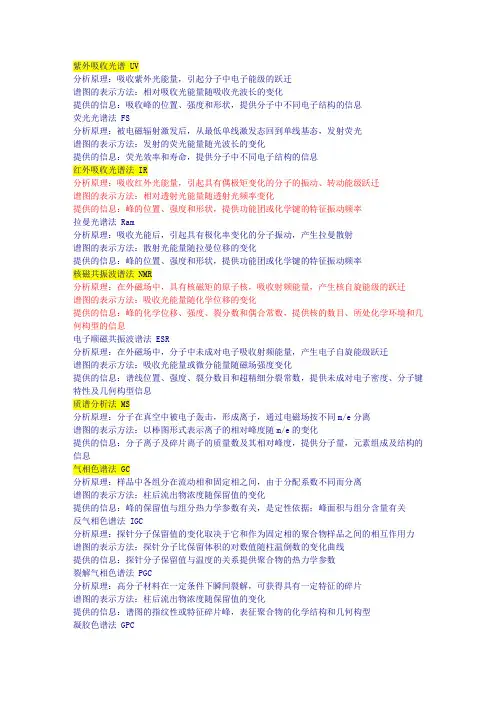
紫外吸收光谱 UV分析原理:吸收紫外光能量,引起分子中电子能级的跃迁谱图的表示方法:相对吸收光能量随吸收光波长的变化提供的信息:吸收峰的位置、强度和形状,提供分子中不同电子结构的信息荧光光谱法 FS分析原理:被电磁辐射激发后,从最低单线激发态回到单线基态,发射荧光谱图的表示方法:发射的荧光能量随光波长的变化提供的信息:荧光效率和寿命,提供分子中不同电子结构的信息红外吸收光谱法 IR分析原理:吸收红外光能量,引起具有偶极矩变化的分子的振动、转动能级跃迁谱图的表示方法:相对透射光能量随透射光频率变化提供的信息:峰的位置、强度和形状,提供功能团或化学键的特征振动频率拉曼光谱法 Ram分析原理:吸收光能后,引起具有极化率变化的分子振动,产生拉曼散射谱图的表示方法:散射光能量随拉曼位移的变化提供的信息:峰的位置、强度和形状,提供功能团或化学键的特征振动频率核磁共振波谱法 NMR分析原理:在外磁场中,具有核磁矩的原子核,吸收射频能量,产生核自旋能级的跃迁谱图的表示方法:吸收光能量随化学位移的变化提供的信息:峰的化学位移、强度、裂分数和偶合常数,提供核的数目、所处化学环境和几何构型的信息电子顺磁共振波谱法 ESR分析原理:在外磁场中,分子中未成对电子吸收射频能量,产生电子自旋能级跃迁谱图的表示方法:吸收光能量或微分能量随磁场强度变化提供的信息:谱线位置、强度、裂分数目和超精细分裂常数,提供未成对电子密度、分子键特性及几何构型信息质谱分析法 MS分析原理:分子在真空中被电子轰击,形成离子,通过电磁场按不同m/e分离谱图的表示方法:以棒图形式表示离子的相对峰度随m/e的变化提供的信息:分子离子及碎片离子的质量数及其相对峰度,提供分子量,元素组成及结构的信息气相色谱法 GC分析原理:样品中各组分在流动相和固定相之间,由于分配系数不同而分离谱图的表示方法:柱后流出物浓度随保留值的变化提供的信息:峰的保留值与组分热力学参数有关,是定性依据;峰面积与组分含量有关反气相色谱法 IGC分析原理:探针分子保留值的变化取决于它和作为固定相的聚合物样品之间的相互作用力谱图的表示方法:探针分子比保留体积的对数值随柱温倒数的变化曲线提供的信息:探针分子保留值与温度的关系提供聚合物的热力学参数裂解气相色谱法 PGC分析原理:高分子材料在一定条件下瞬间裂解,可获得具有一定特征的碎片谱图的表示方法:柱后流出物浓度随保留值的变化提供的信息:谱图的指纹性或特征碎片峰,表征聚合物的化学结构和几何构型凝胶色谱法 GPC分析原理:样品通过凝胶柱时,按分子的流体力学体积不同进行分离,大分子先流出谱图的表示方法:柱后流出物浓度随保留值的变化提供的信息:高聚物的平均分子量及其分布热重法 TG分析原理:在控温环境中,样品重量随温度或时间变化谱图的表示方法:样品的重量分数随温度或时间的变化曲线提供的信息:曲线陡降处为样品失重区,平台区为样品的热稳定区热差分析 DTA分析原理:样品与参比物处于同一控温环境中,由于二者导热系数不同产生温差,记录温度随环境温度或时间的变化谱图的表示方法:温差随环境温度或时间的变化曲线提供的信息:提供聚合物热转变温度及各种热效应的信息示差扫描量热分析 DSC分析原理:样品与参比物处于同一控温环境中,记录维持温差为零时,所需能量随环境温度或时间的变化谱图的表示方法:热量或其变化率随环境温度或时间的变化曲线提供的信息:提供聚合物热转变温度及各种热效应的信息静态热―力分析 TMA分析原理:样品在恒力作用下产生的形变随温度或时间变化谱图的表示方法:样品形变值随温度或时间变化曲线提供的信息:热转变温度和力学状态动态热―力分析 DMA分析原理:样品在周期性变化的外力作用下产生的形变随温度的变化谱图的表示方法:模量或tgδ随温度变化曲线提供的信息:热转变温度模量和tgδ透射电子显微术 TEM分析原理:高能电子束穿透试样时发生散射、吸收、干涉和衍射,使得在相平面形成衬度,显示出图象谱图的表示方法:质厚衬度象、明场衍衬象、暗场衍衬象、晶格条纹象、和分子象提供的信息:晶体形貌、分子量分布、微孔尺寸分布、多相结构和晶格与缺陷等扫描电子显微术 SEM分析原理:用电子技术检测高能电子束与样品作用时产生二次电子、背散射电子、吸收电子、X射线等并放大成象谱图的表示方法:背散射象、二次电子象、吸收电流象、元素的线分布和面分布等提供的信息:断口形貌、表面显微结构、薄膜内部的显微结构、微区元素分析与定量元素分析等。

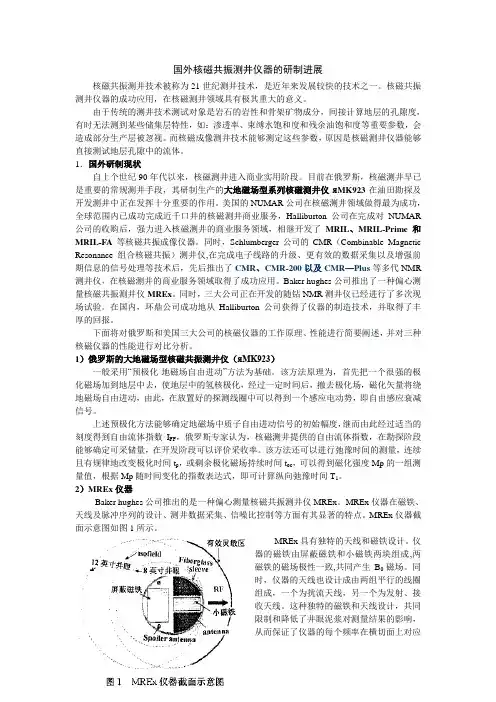
国外核磁共振测井仪器的研制进展核磁共振测井技术被称为21世纪测井技术,是近年来发展较快的技术之一。
核磁共振测井仪器的成功应用,在核磁测井领域具有极其重大的意义。
由于传统的测井技术测试对象是岩石的岩性和骨架矿物成分,间接计算地层的孔隙度,有时无法测到某些储集层特性,如:渗透率、束缚水饱和度和残余油饱和度等重要参数,会造成部分生产层被忽视。
而核磁成像测井技术能够测定这些参数,原因是核磁测井仪器能够直接测试地层孔隙中的流体。
1.国外研制现状自上个世纪90年代以来,核磁测井进入商业实用阶段。
目前在俄罗斯,核磁测井早已是重要的常规测井手段,其研制生产的大地磁场型系列核磁测井仪яMK923在油田勘探及开发测井中正在发挥十分重要的作用。
美国的NUMAR公司在核磁测井领域做得最为成功,全球范围内已成功完成近千口井的核磁测井商业服务,Halliburton公司在完成对NUMAR 公司的收购后,强力进入核磁测井的商业服务领域,相继开发了MRIL、MRIL-Prime和MRIL-FA等核磁共振成像仪器。
同时,Schlumberger公司的CMR(Combinable Magnetic Resonance 组合核磁共振)测井仪,在完成电子线路的升级、更有效的数据采集以及增强前期信息的信号处理等技术后,先后推出了CMR、CMR-200以及CMR—Plus等多代NMR 测井仪,在核磁测井的商业服务领域取得了成功应用。
Baker hughes公司推出了一种偏心测量核磁共振测井仪MREx。
同时,三大公司正在开发的随钻NMR测井仪已经进行了多次现场试验。
在国内,环鼎公司成功地从Halliburton公司获得了仪器的制造技术,并取得了丰厚的回报。
下面将对俄罗斯和美国三大公司的核磁仪器的工作原理、性能进行简要阐述,并对三种核磁仪器的性能进行对比分析。
1)俄罗斯的大地磁场型核磁共振测井仪(яMK923)一般采用“预极化-地磁场自由进动”方法为基础。

看完这篇推文就懂NMR了核磁共振波谱法(Nuclear Magnetic Resonance,简写为NMR)与紫外吸收光谱、红外吸收光谱、质谱被人们称为“四谱”,是对各种有机和无机物的成分、结构进行定性分析的最强有力的工具之一,亦可进行定量分析。
(核磁共振仪)原理在强磁场中,某些元素的原子核和电子能量本身所具有的磁性,被分裂成两个或两个以上量子化的能级。
吸收适当频率的电磁辐射,可在所产生的磁诱导能级之间发生跃迁。
在磁场中,这种带核磁性的分子或原子核吸收从低能态向高能态跃迁的两个能级差的能量,会产生共振谱,可用于测定分子中某些原子的数目、类型和相对位置。
分类NMR波谱按照测定对象分类可分为:1H-NMR谱(测定对象为氢原子核)、13C-NMR谱及氟谱、磷谱、氮谱等。
有机化合物、高分子材料都主要由碳氢组成,所以在材料结构与性能研究中,以1H谱和13C谱应用最为广泛。
NMR波谱按工作方式可分为两种:1、连续波核磁共振谱仪(CW-NMR)射频振荡器产生的射频波按频率大小有顺序地连续照射样品,可得到频率谱;2、脉冲傅立叶变换谱仪(PET-NMR)射频振荡器产生的射频波以窄脉冲方式照射样品,得到的时间谱经过傅立叶变换得出频率谱。
连续波核磁共振谱仪由磁场、探头、射频发射单元、射频、磁场扫描单元、射频检测单元、数据处理仪器控制等部分组成。
磁铁用来产生磁场,主要有三种:频率大的仪器,分辨率好、灵敏度高、图谱简单易于分析。
用途除了运用在医学成像检查方面,在分析化学和有机分子的结构研究及材料表征中运用最多。
1. 有机化合物结构鉴定一般根据化学位移鉴定基团;由耦合分裂峰数、偶合常数确定基团联结关系;根据各H峰积分面积定出各基团质子比。
核磁共振谱可用于化学动力学方面的研究,如分子内旋转,化学交换等,因为它们都影响核外化学环境的状况,从而谱图上都应有所反映。
2. 高分子材料的NMR成像技术核磁共振成像技术已成功地用来探测材料内部的缺陷或损伤,研究挤塑或发泡材料,粘合剂作用,孔状材料中孔径分布等。

第三章 NMR 实验技术基础1 NMR 仪器如图,现代超导核磁谱仪的主要组成部分包括:1. 超导磁体Magnet 包括Field Lock ,Shim Coils2. 探头Probe 内有RF Coils ,Gradient Coils3. 脉冲编程器及射频放大器4. 接收器5. 数据采集及处理计算机At the top of the schematic representation, you will find the superconducting magnet of the NMR spectrometer. The magnet produces the Bo field necessary for the NMR experiments. Immediately within the bore of the magnet are the shim coils for homogenizing the Bo field.Within the shim coils is the probe. The probe contains the RF coils for producing the B1 magnetic field necessary to rotate the spins. The RF coil also detects the signal from the spins within the sample. The sample is positioned within the RF coil of the probe. Some probes also contain a set of gradient coils. These coils produce a gradient in Bo along the X, Y , or Z axis. Gradient coils are used for for gradient enhanced spectroscopy, diffusion, and NMR microscopy experiments. The heart of the spectrometer is the computer. It controls all of the components of thespectrometer. The RF components under control of the computer are the RF frequency source and pulse programmer. The source produces a sine wave of the desired frequency. The pulse programmer sets the width, and in some cases the shape, of the RF pulses. The RF amplifier increases the pulses power from milli Watts to tens or hundreds of Watts. The computer alsocontrols the gradient pulse programmer which sets the shape and amplitude of gradient fields. The gradient amplifier increases the power of the gradient pulses to a level sufficient to drive the gradient coils. The operator of the spectrometer gives input to the computer through a console terminal with a mouse and keyboard. Some spectrometers also have a separate small interface for carrying out some of the more routine procedures on the spectrometer. A pulse sequence isselected and customized from the console terminal. The operator can see spectra on a video display located on the console and can make hard copies of spectra using a printer.1. 超导磁体MagnetMagnet主要要求:a 高磁场强度,分辨率与B0成正比,而灵敏度与B032成正比,故750MHz较600MHz的分辨率提高25%,而灵敏度提高40%b 高均匀性,目前可达10-9c 高稳定性The NMR magnet is one of the mostexpensive components of the nuclearmagnetic resonance spectrometer system.Most magnets are of the superconductingtype. A superconducting magnet has anelectromagnet made of superconductingwire. Superconducting wire has aresistance approximately equal to zerowhen it is cooled to a temperature close toabsolute zero (-273.15 C or 0 K) byemersing it in liquid helium. Once currentis caused to flow in the coil it willcontinue to flow for as long as the coil iskept at liquid helium temperatures.(Some losses do occur over time due to theinfinitesimally small resistance of the coil. These losses are on the order of a ppm of the main magnetic field per year.) The length of superconducting wire in the magnet is typically several miles. This wire is wound into a multi -turn solenoid or coil. The coil of wire and cryroshim coils are kept at a temperature of 4.2K by immersing it in liquid helium. The coil and liquid helium are kept in a large dewar. This dewar is typically surrounded by a liquid nitrogen (77.4K) dewar, which acts as a thermal buffer between the room temperature air (293K) and the liquid helium.The following image is an actual cut -away view of asuperconducting magnet. The magnet is supported by threelegs, and the concentric nitrogen and helium dewars aresupported by stacks coming out of the top of the magnet. Aroom temperature bore hole extends through the center of theassembly. The sample probe and shim coils are located withinthis bore hole. Also depicted in this picture is the liquidnitrogen level sensor, an electronic assembly for monitoringthe liquid nitrogen level.Going from the outside of the magnet to the inside, wesee a vacuum region followed by a liquid nitrogen reservoir.The vacuum region is filled with several layers of a reflectivemylar film. The function of the mylar is to reflect thermal photons, and thus diminish heat from entering the magnet. Within the inside wall of the liquid nitrogen reservoir, we see anothervacuum filled with some reflective mylar. The liquid helium reservoir comes next. This reservoir houses the superconducting solenoid or coil of wire.Taking a closer look at the solenoid it is clear to see the coil and the bore tube extending through the magnet.Field LockIn order to produce a high resolutionNMR spectrum of a sample, especially onewhich requires signal averaging or phasecycling, you need to have a temporallyconstant and spatially homogeneous magneticfield. Consistency of the Bo field over timewill be discussed here; homogeneity will bediscussed in the next section of this chapter.The field strength might vary over time due toaging of the magnet, movement of metal objects near the magnet, and temperature fluctuations. Here is an example of a one line NMR spectrum of cyclohexane recorded while the Bo magnetic field was drifting a very significant amount. The field lock can compensate for these variations.The field lock is a separate NMRspectrometer within your spectrometer. Thisspectrometer is typically tuned to thedeuterium NMR resonance frequency. Itconstantly monitors the resonance frequencyof the deuterium signal and makes minorchanges in the Bo magnetic field to keep theresonance frequency constant. The deuteriumsignal comes from the deuterium solvent usedto prepare the sample. The animation window contains plots of the deuterium resonance lock frequency, the small additional magnetic field used to correct the lock frequency, and the resultant Bo field as a function of time while the magnetic field is drifting. The lock frequency plot displays the frequency without correction. In reality, this frequency would be kept constant by the application of the lock field which offsets the drift.On most NMR spectrometers the deuterium lock serves a second function. It provides the reference. The resonance frequency of the deuterium signal in many lock solvents is well known. Therefore the difference in resonance frequency of the lock solvent and TMS is also known. As a consequence, TMS does not need to be added to the sample to set reference; the spectrometer can use the lock frequency to calculate reference.Shim CoilsThe purpose of shim coils on a spectrometer is to correct minor spatial inhomogeneities in the Bo magnetic field. These inhomogeneities could be caused by the magnet design, materials in the probe, variations in the thickness of the sample tube, sample permeability, and ferromagnetic materials around the magnet. A shim coil is designed to create a small magnetic field which will oppose and cancel out an inhomogeneity in the Bo magnetic field. Because these variations may exist in a variety of functional forms (linear, parabolic, etc.), shim coils are needed which can create a variety of opposing fields. Some of the functional forms are listed in the table below.Shim Coil Functional FormsShim FunctionZ0Z, Z2, Z3, Z4, Z5X, XZ, XZ2, X2Y2, XY , Y , YZ, YZ2XZ3, X2Y2Z, YZ3, XYZ, X3, Y3By passing the appropriate amount of current througheach coil a homogeneous Bo magnetic field can beachieved. The optimum shim current settings are found byeither minimizing the linewidth, maximizing the size of theFID, or maximizing the signal from the field lock. On mostspectrometers, the shim coils are controllable by thecomputer. A computer algorithm has the task of finding thebest shim value by maximizing the lock signal.2. 探头Sample ProbeThe sample probe is the name given to that part of the spectrometer which accepts the sample, sends RF energy into the sample, and detects the signal emanating from the sample. It contains the RF coil, sample spinner, temperature controlling circuitry, and gradient coils. The RF coil and gradient coils will be described in the next two sections. The sample spinner and temperature controlling circuitry will be described here.The purpose of the sample spinner is to rotate the NMRsample tube about its axis. In doing so, each spin in the samplelocated at a given position along the Z axis and radius from the Zaxis, will experience the average magnetic field in the circledefined by this Z and radius. The net effect is a narrower spectrallinewidth. To appreciate this phenomenon, consider the following examples. In picture an axial cross section of a cylindrical tube containing sample. In a very homogeneous Bo magnetic field this sample will yield a narrow spectrum. In a more inhomogeneous field the sample will yield a broader spectrum due to the presence of lines from the parts of the sample experiencing different Bo magnetic fields. When the sample is spun about its z -axis, inhomogeneities in the X and Y directions are averaged out and the NMR line width becomes narrower.Many scientists need to examine properties of their samples as a function of temperature. As a result many instruments have the ability to maintain the temperature of the sample above and below room temperature. Air or nitrogen which has been warmed or cooled is passed over the sample to heat or cool the sample. The temperature at the sample is monitored with the aid of a thermocouple and electronic circuitry maintains the temperature by increasing or decreasing the temperature of the gas passing over the sample.RF CoilsRF coils create the B1 field which rotates thenet magnetization in a pulse sequence. They alsodetect the transverse magnetization as it precesses inthe XY plane. Most RF coils on NMR spectrometersare of the saddle coil design and act as thetransmitter of the B1 field and receiver of RF energyfrom the sample. You may find one or more RF coilsin a probe.Each of these RF coils must resonate, that isthey must efficiently store energy, at the Larmorfrequency of the nucleus being examined with theNMR spectrometer. All NMR coils are composed of an inductor, or inductive elements, and a set of capacitive elements. The resonant frequency, , of an RF coil is determined by the inductance (L) and capacitance (C) of the inductor capacitor circuit. RF coils used in NMR spectrometers need to be tuned for the specific sample being studied. An RF coil has a bandwidth or specific range of frequencies at which it resonates. When you place a sample in an RF coil, the conductivity and dielectric constant of the sample affect the resonance frequency. If this frequency is different from the resonance frequency of the nucleus you are studying, the coil will not efficiently set up the B1 field nor efficiently detect the signal from the sample. You will be rotating the net magnetization by an angle less than 90 degrees when you think you are rotating by 90 degrees. This will produce less transverse magnetization and less signal. Furthermore, because the coil will not be efficiently detecting the signal, your signal -to -noise ratio will be poor.The B1 field of an RF coil must be perpendicular to the Bo magnetic field. Anotherrequirement of an RF coil in an NMR spectrometer is that the B1 field needs to be homogeneous over the volume of your sample. If it is not, you will be rotating spins by a distribution of rotation angles and you will obtain strange spectra.Gradient CoilsThe gradient coils produce the gradients in the Bo magnetic field needed for performing gradient enhanced spectroscopy, diffusion measurements, and NMR microscopy. The gradient coils are located inside the RF probe. Not all probes have gradient coils, and not all NMR spectrometers have the hardware necessary to drive these coils.The gradient coils are room temperature coils (i.e. do not require cooling with cryogens to operate) which, because of their configuration, create the desired gradient. Since the vertical bore superconducting magnet is most common, the gradient coil system will be described for this magnet.Assuming the standard magnetic resonance coordinatesystem, a gradient in Bo in the Z direction is achieved with anantihelmholtz type of coil. Current in the two coils flow inopposite directions creating a magnetic field gradient betweenthe two coils. The B field at the center of one coil adds to theBo field, while the B field at the center of the other coilsubtracts from the Bo field.The X and Y gradients in the Bo field are created by apair of figure -8 coils. The X axis figure -8 coils create agradient in Bo in the X direction due to the direction of thecurrent through the coils. The Y axis figure -8 coils providesa similar gradient in Bo along the Y axis.3. 脉冲编程器及射频放大器包括频率综合器,放大器及有关的电子器件。