基于MC13213的单芯片ZigBee平台的物理层协议研究与实现_吴瑾
- 格式:pdf
- 大小:533.08 KB
- 文档页数:5
ZigBee芯片厂家对比2008年04月12日星期六10:27 一、ZigBee无线技术一鸣惊人ZigBee是一种崭新的,专注于低功耗、低成本、低复杂度、低速率的近程无线网络通信技术。
也是目前嵌入式应用的一个大热点。
ZigBee的特点主要有以下几个方面:1 低功耗。
在低耗电待机模式下,2节5号干电池可支持1个节点工作6~24个月,甚至更长。
这是ZigBee的突出优势。
相比较,蓝牙能工作数周、WiFi可工作数小时。
2 低成本。
通过大幅简化协议(不到蓝牙的1/10),降低了对通信控制器的要求,按预测分析,以8051的8位微控制器测算,全功能的主节点需要32KB代码,子功能节点少至4KB 代码,而且ZigBee免协议专利费。
3 低速率。
ZigBee工作在250kbps的通讯速率,满足低速率传输数据的应用需求。
4 近距离。
传输范围一般介于10~100m之间,在增加RF发射功率后,亦可增加到1~3km。
这指的是相邻节点间的距离。
如果通过路由和节点间通信的接力,传输距离将可以更远。
5 短时延。
ZigBee的响应速度较快,一般从睡眠转入工作状态只需15ms,节点连接进入网络只需30ms,进一步节省了电能。
相比较,蓝牙需要3~10 s、WiFi需要3 s。
6 高容量。
ZigBee可采用星状、片状和网状网络结构,由一个主节点管理若干子节点,最多一个主节点可管理254个子节点;同时主节点还可由上一层网络节点管理,最多可组成65000个节点的大网。
7 高安全。
ZigBee提供了三级安全模式,包括无安全设定、使用接入控制清单(ACL)防止非法获取数据以及采用高级加密标准(AES128)的对称密码,以灵活确定其安全属性。
8 免执照频段。
采用直接序列扩频在工业科学医疗2.4GHz(全球) (ISM)频段。
ZigBee在2004年推出2004(Z igBee 1.0)的基础上,年前又推出了功能更加强大的ZigBee 2006协议栈,增加了Z igBee PRO扩展指令集,功能更加强大。


总733期第三十五期2020年12月河南科技Journal of Henan Science and Technology基于ZigBee的医院病房呼叫系统设计姬智(南阳理工学院,河南南阳473004)摘要:近年来,无线技术等智能化技术发展迅猛,其中,ZigBee技术属于短距离无线通信技术,具有网络容量大、传输速率低、成本小、功耗低、稳定和灵活等特点,受到社会各界广泛的关注。
本文主要探讨根据ZigBee 技术设计的无线病房呼叫系统,以满足医院对病房呼叫系统的需求,方便患者应用,提高护理服务质量,为广大患者提供更加优质、全面、系统的服务,提高患者的满意度。
本设计方案以CC2530型芯片作为主控芯片,配有液晶显示屏和按键,兼具报警、振动等功能,便于医护人员与患者进行实时交流和沟通。
本设计采用C语言编程并经过仿真论证,能够确保系统高效运转,有助于及时满足患者的治疗和康复需求。
关键词:ZigBee;医院病房呼叫系统;功耗;网络容量;传输速率;患者满意度中图分类号:R197.3;TN92文献标识码:A文章编号:1003-5168(2020)35-0030-03 Design of Hospital Ward Call System Based on ZigBeeJI Zhi(Nanyang Institute of Technology,Nanyang Henan473004)Abstract:In recent years,intelligent technologies such as wireless technology have developed rapidly,among them, ZigBee technology belongs to short-distance wireless communication technology,which has the characteristics of large network capacity,low transmission rate,low cost,low power consumption,stability and flexibility,and has at⁃tracted wide attention from all walks of life.This paper mainly discussed the wireless ward call system designed ac⁃cording to ZigBee technology to meet the hospital's demand for the ward call system,facilitate patient application,im⁃prove the quality of nursing service,provide more high-quality,comprehensive and systematic services for the majori⁃ty of patients,and improve patient satisfaction.This design uses the CC2530chip as the main control chip,equipped with an LCD display and buttons,and has functions such as alarm and vibration,which facilitates real-time communi⁃cation and communication between medical staff and patients.This design adopts C language programming and has undergone simulation demonstration,which can ensure the efficient operation of the system and help to meet the treat⁃ment and rehabilitation needs of patients in time.Keywords:ZigBee;hospital ward call system;power consumption;network capacity;transmission rate;patient satis⁃faction基于ZigBee的医院病房呼叫系统具有呼叫、显示、监听及信息存储等功能,便于对医院进行智能化管理,有利于患者及其家属及时呼叫护士,同时有助于护士及时准确判断患者病情并及时反馈给临床医生,提高救治效率,改善患者生存品质。

Zigbee 解决方案总结一.非开源协议栈1.freescale 解决方案协议栈种类:1.1 802.15.4标准mac1.2 SMAC1.3 SynkroRF1.4 ZigBee RF4CE1.5 ZigBee 2007最简单的就是SMAC,是面向最简单的点对点应用的,不涉及网络的概念;其次是IEEE802.15.4,一般用来组建简单的星型网络,而且提供了源代码,可以清楚地看到网络连接的每个步骤,分别调用了哪些函数;BeeStack(符合zigbee 2007)是提供的最复杂的协议栈,但是看不到代码,它提供给你一些封装好的函数,比如创建网络函数,你直接调用它,协调器就把网络创建好了,终端节点调用它则寻找可以加入的ZigBee网络并尝试加入。
其中硬件平台可以为下面中的任一种:MC13202 (2.4 GHz射频收发器)MC13213 (2.4 GHz射频收发器和带60K闪存的8位MCU)MC13224V (2.4 GHz平台级封装(PIP) –带有128KB闪存、96KB RAM、80KB ROM的32位TDMI ARM7处理器)MC13233 (带有HCS08 MCU的2.4 GHz片上系统)MC13202没有自带mcu,在做应用时,需要用户在自己的扩展板上加上mcu,既需要实现对外围设备的底层控制,也需要实现协议栈。
下面的几种均有自带mcu,协议栈的实现在自带的mcu 上实现,功能较简单的可直接使用片上的mcu资源进行控制;功能复杂的应用,最好协议栈实现与外围控制分开,大多数应用都选择arm芯片作为控制芯片;详细信息可以查看/products/rf/ZigBee.asp 2.microchip 解决方案协议栈种类:ZigBee® Smart Energy Profile (SEP) SuiteZigBee® PROZigBee® RF4CE均是一整套的协议集,价格不菲;硬件平台:Pic18(mcu)+MRF24J40(2.4GHZ 射频收发器)+天线与freescale 的mc13202相似,MRF24J40也只是射频收发器,不包含mcu,协议栈的实现需要借助于外围的mcu,当然微芯公司选择的是pic18及以上的芯片作为其主控mcu,通过spi接口与MRF24J40通信,查询其寄存器的状态,实现协议栈功能。

Zigbee技术主流芯片调研1、Zigbee芯片调研当今市场已有大量集成Zigbee协议和射频电路的芯片。
以下是市场上主流的生成Zigbee的公司及其生产的典型Zigbee芯片。
公司TI FREESCALE ATMEL Nordic芯片CC2530 MC1321 AT86RF230 nRF24E1/nRF9E5MCU内核8051HCS08 无(通过SPI接口由外接MCU连接)8051通过在淘宝上的调查,TI公司的CC2530和FREESCALE的MC1321用户量比较大,有大量的公司提供基于这两款芯片的Zigbee模块,使用这些模块可以减少大量的硬件调试工作,而较容易的实现我们所需的传输功能。
以下就这两类主流芯片进行详细介绍。
1.1 CC2530调研CC2530是市场最主流的Zigbee芯片,TI公司推出的ZIGBEE网络处理器,将复杂的ZIGBEE网络协议栈,处理成了简单的用户接口命令,用户只要使用任何简单的单片机(微控制器),就可以容易的实现对ZIGBEE网络的控制;TI推出这个芯片的目的,就是希望ZIGBEE容易被使用。
CC2530是TI公司推出的最新一代ZigBee标准芯片,适用于2.4GHz、IEEE802.15.4、ZigBee和 RF4CE应用。
CC2530包括了极好性能的一流RF收发器,工业标准增强性8051MCU,系统中可编程的闪存,8KB RAM以及许多其它功能强大的特性,可广泛应用在2.4-GHzIEEE802.15.4系统,RF4CE遥控制系统,ZigBee系统,家庭/建筑物自动化,照明系统,工业控制和监视,低功耗无线传感器网络,消费类电子和卫生保健。
主要参数如下:1 MCU 使用 8051 8-bit 单周期内核,较标准8051快8倍;2128kByte FLASH 存储器+ 8kByte RAM;3 RTC/2USART/2PWM/SPI/DES加密电/看门狗电路等等;47~12位ADC电路;5高频部分全部集成在芯片上,工作在2.4Ghz, 低功率消耗;6ZigBee 无线网络节点, 包括网络协调, 路由,简单节点功能;CC2430 采用Chipcon 公司最新的Smart RF 03 技术和 0.18CMOS工艺制造,7x7 mm QLP 48 包装;无线频率:2.4GHz无线协议:ZigBee2007 /PRO发射电流:34mA(最大)接收电流:25mA(最大)接收灵敏度:-96DBm1.2 MC13213/MC13224调研飞思卡尔的ZigBee方案将射频收发器与低功耗MCU集成至一颗单芯片,并提供从16K~60K的灵活Flash存储空间。
Freescale Semiconductor Technical DataFreescale reserves the right to change the detail specifications as may be required to permit improvements in the design of its products.Document Number: MC1321xRev. 0.0, 03/2006MC1321xPackage InformationCase 1664-0171-pin LGA [9x9 mm]Ordering InformationDevice Device MarkingPackage MC132********LGA MC132********LGA MC132********LGA MC13214113214LGA1See Table 1 for more details.1IntroductionThe MC1321x family is Freescale’s second-generation ZigBee platform which incorporates a low power 2.4 GHz radio frequency transceiver and an 8-bitmicrocontroller into a single 9x9x1 mm 71-pin LGA package. The MC1321x solution can be used for wireless applications from simple proprietary point-to-point connectivity to a complete ZigBee mesh network. The combination of the radio and a microcontroller in a small footprint package allows for a cost-effective solution.The MC1321x contains an RF transceiver which is an IEEE 802.15.4-compliant radio that operates in the 2.4 GHz ISM frequency band. The transceiver includes a low noise amplifier, 1mW nominal output power, PA with internal voltage controlled oscillator (VCO), integrated transmit/receive switch, on-board power supply regulation, and full spread-spectrum encoding and decoding.The MC1321x also contains a microcontroller based on the HCS08 Family of Microcontroller Units (MCU) and can provide up to 60KB of flash memory and 4KB of RAM. The onboard MCU allows the communicationsMC13211/212/213/214ZigBee ™- Compliant Platform - 2.4 GHz Low Power Transceiver for the IEEE ® 802.15.4 Standard plus MicrocontrollerContents1Introduction . . . . . . . . . . . . . . . . . . . . . . . . . . 12MC1321x Pin Assignment and Connections 83MC1321x Serial Peripheral Interface (SPI) . 144IEEE 802.15.4 Modem . . . . . . . . . . . . . . . . . . 165MCU . . . . . . . . . . . . . . . . . . . . . . . . . . . . . . . . 256System Electrical Specification . . . . . . . . . 467Application Considerations . . . . . . . . . . . . . 638Mechanical Diagrams . . . . . . . . . . . . . . . . . . 68stack and also the application to reside on the same system-in-package (SIP). The MC1321x family is organized as follows:•The MC13211 has 16KB of flash and 1KB of RAM and is an ideal solution for low cost, proprietary applications that require wireless point-to-point or star network connectivity. TheMC13211 combined with the Freescale Simple MAC (SMAC) provides the foundation forproprietary applications by supplying the necessary source code and application examples to get users started on implementing wireless connectivity.•The MC13212 contains 32K of flash and 2KB of RAM and is intended for use with the Freescale fully compliant 802.15.4 MAC. Custom networks based on the 802.15.4 standard MAC can be implemented to fit user needs. The 802.15.4 standard supports star, mesh and cluster treetopologies as well as beaconed networks.•The MC13213 contains 60K of flash and 4KB of RAM and is also intended for use with the Freescale fully compliant 802.15.4 MAC where larger memory is required. In addition, this device can support ZigBee applications that use a stack from 3rd party vendors.•The MC13214 is a fully compliant ZigBee platform. The MC13214 contains 60K of flash and 4KB of RAM and uses the Figure 8 Wireless ZigBee Stack (Z-stack) software. Applications can beadded to develop fully certified ZigBee products.Applications include, but are not limited to, the following:•Residential and commercial automation—Lighting control—Security—Access control—Heating, ventilation, air-conditioning (HV AC)—Automated meter reading (AMR)•Industrial Control—Asset tracking and monitoring—Homeland security—Process management—Environmental monitoring and control—HV AC—Automated meter reading•Health Care—Patient monitoring—Fitness monitoring1.1Ordering InformationTable 1 provides additional details about the MC1321x family.1.2General Platform Features•IEEE 802.15.4 standard compliant on-chip transceiver/modem —2.4GHz—16 selectable channels—Programmable output power •Multiple power saving modes•2V to 3.4V operating voltage with on-chip voltage regulators •-40°C to +85°C temperature range •Low external component count•Supports single 16 MHz crystal clock source operation or dual crystal operation •Support for SMAC, IEEE 802.15.4, and ZigBee software •9mm x 9mm x 1mm 71-pin LGATable 1. Orderable Parts DetailsDevice Operating Temp Range(TA.)Package Memory Options DescriptionMC13211-40° to 85° C LGA1KB RAM, 16KB Flash Intended for proprietary applications and Freescale Simple MAC (SMAC)MC13211R2-40° to 85° C LGATape and Reel 1KB RAM, 16KB Flash Intended for proprietary applications and Freescale Simple MAC (SMAC)MC13212-40° to 85° C LGA2KB RAM, 32KB Flash Intended for IEEE 802.15.4 compliant applications and Freescale 802.15.4 MACMC13212R2-40° to 85° C LGATape and Reel 2KB RAM, 32KB Flash Intended for IEEE 802.15.4 compliant applications and Freescale 802.15.4 MACMC13213-40° to 85° CLGA4KB RAM, 60KB FlashIntended for IEEE 802.15.4 compliant applications and Freescale 802.15.4 MAC.Also supports ZigBee applications that use a stack from a 3rd party vendor.MC13213R2-40° to 85° CLGATape and Reel 4KB RAM, 60KB FlashIntended for IEEE 802.15.4 compliant applications and Freescale 802.15.4 MAC.Also supports ZigBee applications that use a stack from a 3rd party vendor.MC13214-40° to 85° C LGA4KB RAM, 60KB Flash Intended for full ZigBee compliant applications using the F8 Wireless Z-StackMC13214R2-40° to 85° CLGATape and Reel4KB RAM, 60KB FlashIntended for full ZigBee compliant applications using the F8 Wireless Z-Stack1.3Microcontroller Features•Low voltage MCU with 40 MHz low power HCS08 CPU core•Up to 60K flash memory with block protection and security and 4K RAM—MC13211: 16KB Flash, 1KB RAM—MC13212: 32KB Flash, 2KB RAM—MC13213: 60KB Flash, 4KB RAM—MC13214: 60KB Flash, 4KB RAM with ZigBee Z-stack•Low power modes (Wait plus Stop2 and Stop3 modes)•Dedicated serial peripheral interface (SPI) connected internally to 802.15.4 modem•One 4-channel and one 1-channel 16-bit timer/pulse width modulator (TPM) module with selectable input capture, output capture, and PWM capability.•8-bit port keyboard interrupt (KBI)•8-channel 8-10-bit ADC•Two independent serial communication interfaces (SCI)•Multiple clock source options—Internal clock generator (ICG) with 243 kHz oscillator that has +/-0.2% trimming resolution and +/-0.5% deviation across voltage.—Startup oscillator of approximately 8 MHz—External crystal or resonator—External source from modem clock for very high accuracy source or system low-cost option •Inter-integrated circuit (IIC) interface.•In-circuit debug and flash programming available via on-chip background debug module (BDM)—Two comparator and 9 trigger modes—Eight deep FIFO for storing change-of-flow addresses and event-only data—Tag and force breakpoints—In-circuit debugging with single breakpoint•System protection features—Programmable low voltage interrupt (LVI)—Optional watchdog timer (COP)—Illegal opcode detection•Up to 32 MCU GPIO with programmable pullups1.4RF Modem Features•Fully compliant IEEE 802.15.4 transceiver supports 250 kbps O-QPSK data in 5.0 MHz channels and full spread-spectrum encode and decode•Operates on one of 16 selectable channels in the 2.4 GHz ISM band•-1 dBm to 0 dBm nominal output power, programmable from -27 dBm to +3 dBm typical•Receive sensitivity of <-92 dBm (typical) at 1% PER, 20-byte packet, much better than the IEEE 802.15.4 specification of -85 dBm•Integrated transmit/receive switch•Dual PA ouput pairs which can be programmed for full differential single-port or dual-port operation that supports an external LNA and/or PA.•Three low power modes for increased battery life•Programmable frequency clock output for use by MCU•Onboard trim capability for 16 MHz crystal reference oscillator eliminates need for external variable capacitors and allows for automated production frequency calibration •Four internal timer comparators available to supplement MCU timer resources•Supports both packet data mode and streaming data mode•Seven GPIO to supplement MCU GPIO1.5Software FeaturesFreescale provides a wide range of software functionality to complement the MC1321x hardware. There are three levels of application solutions:1.Simple proprietary wireless connectivity.er networks built on the IEEE 802.15.4 MAC standard.3.ZigBee-compliant network stack.1.5.1Simple MAC (SMAC)•Small memory footprint (about 3 Kbytes typical)•Supports point-to-point and star network configurations•Proprietary networks•Source code and application examples provided1.5.2IEEE 802.15.4-Compliant MAC•Supports star, mesh and cluster tree topologies•Supports beaconed networks•Supports GTS for low latency•Multiple power saving modes (idle doze, hibernate)1.5.3ZigBee-Compliant Network Stack•Supports ZigBee 1.0 specification•Supports star, mesh and tree networks•Advanced Encryption Standard (AES) 128-bit security1.6System Block DiagramFigure1 shows a simplified block diagram of the MC1321x solution.Figure1. MC1321x System Level Block Diagram1.7System Clock ConfigurationThe MC321x device allows for a wide array of system clock configurations:•Pins are provided for a separate external clock source for the CPU. The external clock source can by derived from a crystal oscillator or from an external clock source•Pins are provided for a 16 MHz crystal for the modem clock source (required)•The modem crystal oscillator frequency can be trimmed through programming to maintain the tight tolerances required by IEEE 802.15.4•The modem provides a CLKO programmable frequency clock output that can be used as an external source to the CPU. As a result, a single crystal system clock solution is possible •Out of reset, the MCU uses an internally generated clock (approximately 8-MHz) for start-up. This allows recovery from stop or reset without a long crystal start-up delay•The MCU contains an internal clock generator (which can be trimmed) that can be used to run the MCU for low power operation. This internal reference is approximately 243 kHzFigure2. MC1321x Single Crystal System Clock Structure2MC1321x Pin Assignment and Connections Figure3 shows the MC1321x pinout.2.1Pin DefinitionsTable2 details the MC1321x pinout and functionality.Table2. Pin Function DescriptionPin #Pin Name Type Description Functionality1PTA3/KBI1P3DigitalInput/Output MCU Port A Bit 3 / Keyboard Input Bit 32PTA4/KBI1P4DigitalInput/Output MCU Port A Bit 4 / Keyboard Input Bit 43PTA5/KBI1P5DigitalInput/Output MCU Port A Bit 5 / Keyboard Input Bit 54PTA6/KBI1P6DigitalInput/Output MCU Port A Bit 6 / Keyboard Input Bit 65PTA7/KBI1P7DigitalInput/Output MCU Port A Bit 7 / Keyboard Input Bit 76VDDAD Power Input MCU power supply to ATD Decouple to ground.7PTG0/BKGND/MS DigitalInput/Output MCU Port G Bit 0 /Background / Mode SelectPTG0 is output only. Pin is I/O when used as BDMfunction.8PTG1/XTAL DigitalInput/Output/Output MCU Port G Bit 1 / Crystaloscillator outputFull I/O when not used as clock source.9PTG2/EXTAL DigitalInput/Output/Input MCU Port G Bit 2 / Crystaloscillator inputFull I/O when not used as clock source.10CLKO Digital Output Modem Clock Output Programmable frequencies of:16 MHz, 8 MHz, 4 MHz, 2 MHz, 1 MHz, 62.5 kHz,32.786+ kHz (default),and 16.393+ kHz.11RESET DigitalInput/OutputMCU reset. Active low12PTC0/TXD2DigitalInput/Output MCU Port C Bit 0 / SCI2 TX data out13PTC1/RXD2DigitalInput/Output MCU Port C Bit 1/ SCI2 RX data in14PTC2/SDA1DigitalInput/Output MCU Port C Bit 1/ IIC bus data15PTC3/SCL1DigitalInput/Output MCU Port C Bit 1/ IIC bus clock16PTC4DigitalInput/OutputMCU Port C Bit 417PTC5DigitalInput/OutputMCU Port C Bit 518PTC6DigitalInput/OutputMCU Port C Bit 619PTC7DigitalInput/OutputMCU Port C Bit 720PTE0/TXD1DigitalInput/Output MCU Port E Bit 0 / SCI1 TX data out21PTE1/RXD1DigitalInput/Output MCU Port E Bit 1/ SCI1 RX data in22VDDD Power Output Modem regulated outputsupply voltageDecouple to ground.23VDDINT Power Input Modem digital interfacesupply 2.0 to 3.4 V. Decouple to ground. Connect to Battery.24GPIO5DigitalInput/Output Modem General Purpose Input/Output 525GPIO6DigitalInput/Output Modem General Purpose Input/Output 626GPIO7DigitalInput/Output Modem General Purpose Input/Output 727XTAL1Input Modem crystal referenceoscillator inputConnect to 16 MHz crystal and load capacitor.28XTAL2Input/Output Modem crystal referenceoscillator output Connect to 16 MHz crystal and load capacitor. Do not load this pin by using it as a 16 MHz source. Measure 16 MHz output at CLKO, programmed for 16 MHz.29VDDLO2Power Input Modem LO2 VDD supply Connect to VDDA externally.30VDDLO1Power Input Modem LO1 VDD supply Connect to VDDA externally.31VDDVCO Power Output Modem VCO regulatedsupply bypassDecouple to ground.32VBATT Power Input Modem voltage regulators’inputDecouple to ground. Connect to Battery.33VDDA Power Output Modem analog regulatedsupply output Decouple to ground. Connect to directly VDDLO1 and VDDLO2 externally and to PAO_P andPAO_M through a bias network.34CT_Bias RF ControlOutput Modem biasvoltage/control signal forRF external componentsWhen used with internal T/R switch, providesground reference for RX and VDDA reference forTX. Can also be used as a control signal withexternal LNA, antenna switch, and/or PA.35RFIN_M RF Input(Output)Modem RF input/outputnegativeWhen used with internal T/R switch, this is abi-directional RF port for the internal LNA and PA36RFIN_P RF Input(Output)Modem RF input/outputpositiveWhen used with internal T/R switch, this is abi-directional RF port for the internal LNA and PATable2. Pin Function Description (continued)Pin #Pin Name Type Description Functionality37NC Not used May be grounded or left open38PAO_P RF Output Modem power amplifierRF output positive Open drain. Connect to VDDA through a bias network when used with external balun. Not used when internal T/R switch is used.39PAO_M RF Output Modem power amplifierRF output negative Open drain. Connect to VDDA through a bias network when used with external balun. Not used when internal T/R switch is used.40SM Input Test Mode pin Must be grounded for normal operation41GPIO4DigitalInput/Output Modem General Purpose Input/Output 442GPIO3DigitalInput/Output Modem General Purpose Input/Output 343GPIO2Test Point MCU Port E Bit 6 / ModemGeneral PurposeInput/Output 2Internally connected pins. When gpio_alt_en, Register 9, Bit 7 = 1, GPIO2 functions as a “CRC Valid” indicator.44GPIO1Test Point MCU Port E Bit 7 / ModemGeneral PurposeInput/Output 1Internally connected pins. When gpio_alt_en, Register 9, Bit 7 = 1, GPIO1 functions as an “Out of Idle” indicator.45VDD Power Input MCU main power supply Decouple to ground.46ATTN Test Point MCU Port D Bit 0 / Modemattention inputInternally connected pins.47PTD2/TPM1CH2DigitalInput/Output MCU Port D Bit 2 / TPM1 Channel 248PTD4/TPM2CH1DigitalInput/Output MCU Port D Bit 4 / TPM2 Channel 149PTD5/TPM2CH2DigitalInput/Output MCU Port D Bit 5 / TPM2 Channel 250PTD6/TPM2CH3DigitalInput/Output MCU Port D Bit 6 / TPM2 Channel 351PTD7/TPM2CH4DigitalInput/Output MCU Port D Bit 7 / TPM2 Channel 452PTB0/AD1P0Input/Output MCU Port B Bit 0 / ATDanalogChannel 053PTB1/AD1P1Input/Output MCU Port B Bit 1 / ATDanalog Channel 154PTB2/AD1P2Input/Output MCU Port B Bit 2 / ATDanalog Channel 255PTB3/AD1P3Input/Output MCU Port B Bit 3 / ATDanalog Channel 356PTB4/AD1P4Input/Output MCU Port B Bit 4 / ATDanalog Channel 4Pin #Pin Name Type Description Functionality57PTB5/AD1P5Input/Output MCU Port B Bit 5 / ATDanalog Channel 558PTB6/AD1P6Input/Output MCU Port B Bit 6 / ATDanalog Channel 659PTB7/AD1P7Input/Output MCU Port B Bit 7 / ATDanalog Channel 760VREFH Input MCU high referencevoltage for ATD61VREFL Input MCU low referencevoltage for ATD62PTA0/KBI1P0DigitalInput/Output MCU Port A Bit 0 / Keyboard Input Bit 063PTA1/KBI1P1DigitalInput/Output MCU Port A Bit 1 / Keyboard Input Bit 164PTA2/KBI1P2DigitalInput/Output MCU Port A Bit 2 / Keyboard Input Bit 265TEST Test Point For factory test Do not connect 66TEST Test Point For factory test Do not connect 67TEST Test Point For factory test Do not connect 68TEST Test Point For factory test Do not connect 69TEST Test Point For factory test Do not connect 70TEST Test Point For factory test Do not connect 71TEST Test Point For factory test Do not connectFLAG VSS Power input External package flag.Common VSS Connect to ground.Pin #Pin Name Type Description Functionality2.2Internal Functional InterconnectsThe MCU provides control for the 802.15.4 modem. The required interconnects between the devices are routed onboard the SiP. In addition, the signals are brought out to external pads primarily for use as test points. These signals can be useful when writing and debugging software.Table3. Internal Functional InterconnectsPin #MCU Signal Modem Signal Description43PTE6GPIO2Modem GPIO2 output acts as “CRC Valid” status indicator for Stream DataMode to MCU.44PTE7GPIO1Modem GPIO1 output acts as “Out of Idle” status indicator for Stream DataMode to MCU.46PTD0ATTN MCU Port D Bit 0 drives the attention (ATTN) input of the modem to wakemodem from Hibernate or Doze Mode.PTE5/SPSCK1SPICLK MCU SPI master SPI clock output drives modem SPICLK slave clock input.PTE4/MOSI1MOSI MCU SPI master MOSI output drives modem slave MOSI inputPTE3/MISO1MISO Modem SPI slave MISO output drives MCU master MISO inputPTE2/SS1CE MCU SPI master SS output drives modem slave CE inputIRQ M_IRQ Modem interrupt request M_IRQ output drives MCU IRQ inputPTD1RXTXEN MCU Port D Bit 1 drives the RXTXEN input to the modem to enable TX or RXor CCA operations.PTD3M_RST MCU Port D Bit 3 drives the reset M_RST input to the modem.NOTETo use the MCU and modem signals as described in Table3, the MCU needsto be programmed appropriately for the stated function.3MC1321x Serial Peripheral Interface (SPI)The MC1321x modem and CPU communicate primarily through the onboard SPI command channel. Figure4 shows the SiP internal interconnects with the SPI bus highlighted. The MCU has a single SPI module that is dedicated to the modem SPI interface. The modem is a slave only and the MCU SPI must be programmed and used as a master only. Further, the SPI performance is limited by the modem constraints of 8 MHz SPI clock frequency, and use of the SPI must be programmed to meet the modem SPI protocol.3.1SiP Level SPI Pin ConnectionsThe SiP level SPI pin connections are all internal to the device. Figure4 shows the SiP interconnections with the SPI bus highlighted.Figure4. MC1321x Internal Interconnects Highlighting SPI BusTable4. MC1321x Internal SPI ConnectionsMCU Signal Modem Signal DescriptionPTE5/SPSCK1SPICLK MCU SPI master SPI clock output drives modem SPICLK slave clock input.PTE4/MOSI1MOSI MCU SPI master MOSI output drives modem slave MOSI inputPTE3/MISO1MISO Modem SPI slave MISO output drives MCU master MISO inputPTE2/SS1CE MCU SPI master SS output drives modem slave CE input3.2SPI Features•MCU bus master •Modem bus slave•Programmable SPI clock rate; maximum rate is 8 MHz •Double-buffered transmit and receive at MCU•Serial clock phase and polarity must meet modem requirements (MCU control bits •Slave select programmed to meet modem protocol3.3SPI System Block DiagramFigure 5 shows the SPI system level diagram.Figure 5. SPI System Block DiagramFigure 5 shows the SPI modules of the MCU and modem in the master-slave arrangement. The MCU (master) initiates all SPI transfers. During a transfer, the master shifts data out (on the MOSI pin) to the slave while simultaneously shifting data in (on the MISO pin) from the slave. Although the SPI interface supports simultaneous data exchange between master and slave, the modem SPI protocol only uses data exchange in one direction at a time. The SPSCK signal is a clock output from the master and an input to the slave. The slave device must be selected by a low level on the slave select input (SS1 pin).7654321SPI SHIFTERCLOCK GENERATOR7654321SPI SHIFTER PTE2/SS1SPSCK1MISO1MOS1CESPICLKMISOMOSIMCU (MASTER)MODEM (SLAVE)4IEEE 802.15.4 Modem4.1Block DiagramFigure6. 802.15.4 Modem Block Diagram4.2Data Transfer ModesThe 802.15.4 modem has two data transfer modes:1.Packet Mode — Data is buffered in on-chip RAM2.Streaming Mode — Data is processed word-by-wordThe Freescale 802.15.4 MAC software only supports the streaming mode of data transfer. For proprietary applications, packet mode can be used to conserve MCU resources.4.3Packet StructureFigure7 shows the packet structure of the 802.15.4 modem. Payloads of up to 125 bytes are supported. The 802.15.4 modem adds a four-byte preamble, a one-byte Start of Frame Delimiter (SFD), and aone-byte Frame Length Indicator (FLI) before the data. A Frame Check Sequence (FCS) is calculated and appended to the end of the data.4 bytes 1 byte 1 byte125 bytes maximum 2 bytesPreamble SFD FLI Payload Data FCSFigure7. 802.15.4 modem Packet Structure4.4Receive Path DescriptionIn the receive signal path, the RF input is converted to low IF In-phase and Quadrature (I & Q) signals through two down-conversion stages. A Clear Channel Assessment (CCA) can be performed based upon the baseband energy integrated over a specific time interval. The digital back end performs Differential Chip Detection (DCD), the correlator “de-spreads” the Direct Sequence Spread Spectrum (DSSS) Offset QPSK (O-QPSK) signal, determines the symbols and packets, and detects the data.The preamble, SFD, and FLI are parsed and used to detect the payload data and FCS (which are stored in RAM in Packet Mode). A two-byte FCS is calculated on the received data and compared to the FCS value appended to the transmitted data, which generates a Cyclical Redundancy Check (CRC) result. A parameter of received energy during the reception called the Link Quality Indicator is measured over a 64 µs period after the packet preamble and stored in an SPI register.If the 802.15.4 modem is in Packet Mode, the data is stored in RAM and processed as an entire packet. The MCU is notified that an entire packet has been received via an interrupt.If the 802.15.4 modem is in streaming mode, the MCU is notified by a recurring interrupt on aword-by-word basis.Figure8 shows CCA reported power level versus input power. Note that CCA reported power saturates at about -57 dBm input power which is well above IEEE 802.15.4 Standard requirements. Figure9 shows energy detection/LQI reported level versus input power.NOTEFor both graphs, the required IEEE 802.15.4 Standard accuracy and rangelimits are shown. A 3.5 dBm offset has been programmed into the CCAreporting level to center the level over temperature in the graphs.FigureFigure4.5For the transmit path, the TX data that was previously written to the internal RAM is retrieved (packet mode) or the TX data is clocked in via the SPI (stream mode), formed into packets per the 802.15.4 PHY, spread, and then up-converted to the transmit frequency.If the 802.15.4 modem is in packet mode, data is processed as an entire packet. The data is first loaded into the TX buffer. The MCU then requests that the modem transmit the data. The MCU is notified via an interrupt when the whole packet has successfully been transmitted.In streaming mode, the data is fed to the 802.15.4 modem on a word-by-word basis with an interrupt serving as a notification that the 802.15.4 modem is ready for more data. This continues until the whole packet is transmitted.In both modes, a two-byte FCS is calculated in hardware from the payload data and appended to the packet. This done without intervention from the user.4.6Functional Description4.6.1802.15.4 Modem Operational ModesThe 802.15.4 modem has a number of operational modes that allow for low-current operation. Transition from the Off to Idle mode occurs when M_RST is negated. Once in Idle, the SPI is active and is used to control the IC. Transition to Hibernate and Doze modes is enabled via the SPI. These modes aresummarized, along with the transition times, in Table 5. Current drain in the various modes is listed in Table 8, DC Electrical Characteristics.4.6.2Serial Peripheral Interface (SPI)The MCU directs the 802.15.4 modem, checks its status, and reads/writes data to the device through the 4-wire SPI port. The transceiver operates as a SPI slave device only. A transaction between the host and the 802.15.4 modem occurs as multiple 8-bit bursts on the SPI. The modem SPI signals are:1.Chip Enable (CE) - A transaction on the SPI port is framed by the active low CE input signal. Atransaction is a minimum of 3 SPI bursts and can extend to a greater number of bursts.2.SPI Clock (SPICLK) - The host drives the SPICLK input to the 802.15.4 modem. Data is clockedinto the master or slave on the leading (rising) edge of the return-to-zero SPICLK and data out changes state on the trailing (falling) edge of SPICLK.Table 5. 802.15.4 Modem Mode Definitions and Transition TimesMode DefinitionTransition Time To or From IdleOff All IC functions Off, Leakage only. M_RST asserted. Digital outputs are tri-stated including IRQ10 - 25 ms to Idle Hibernate Crystal Reference Oscillator Off. (SPI not functional.) IC Responds to ATTN. Data is retained.7 - 20 ms to Idle DozeCrystal Reference Oscillator On but CLKO output available only if Register 7, Bit 9 = 1 for frequencies of 1 MHz or less. (SPI not functional.) Responds to ATTN and can be programmed to enter Idle Mode through an internal timer comparator. (300 + 1/CLKO) µs to Idle Idle Crystal Reference Oscillator On with CLKO output available. SPI active.Receive Crystal Reference Oscillator On. Receiver On.144 µs from Idle TransmitCrystal Reference Oscillator On. Transmitter On.144 µs from IdleNOTEFor the MCU, the SPI clock format is the clock phase control bit CPHA = 0and the clock polarity control bit CPOL = 0.3.Master Out/Slave In (MOSI) - Incoming data from the host is presented on the MOSI input.4.Master In/Slave Out (MISO) - The 802.15.4 modem presents data to the master on the MISOoutput.Although the SPI port is fully static, internal memory, timer and interrupt arbiters require an internal clock (CLK core), derived from the crystal reference oscillator, to communicate from the SPI registers to internal registers and memory.4.6.2.1SPI Burst OperationThe SPI port of the MCU transfers data in bursts of 8 bits with most significant bit (MSB) first. The master (MCU) can send a byte to the slave (transceiver) on the MOSI line and the slave can send a byte to the master on the MISO line. Although an 802.15.4 modem transaction is three or more SPI bursts long, the timing of a single SPI burst is shown in Figure10. The maximum SPI clock rate is 8 Mhz from the MCU because the modem is limited by this number.。
智能考勤管理系统是指一套管理公司的员工的上下班考勤记录等相关情况的管理系统。
是考勤软件与考勤硬件结合的产品,一般为HR部门使用,掌握并管理企业的员工出勤动态。
智能考勤管理系统的论文应该怎么写?智能考勤管理系统论文实验室智能考勤与管理系统设计摘要:为提高实验室管理效率,科学管理实验设备,快速方便地完成考勤工作,设计了一种基于校园卡的实验室智能考勤与管理系统。
系统由智能终端和上位机管理系统软件两部分组成。
智能终端以ATmega16为核心,具有RFID读写、LCD显示、Zigbee无线通讯等功能模块,与上位机采用Zigbee无线通讯方式完成各种数据传输。
管理系统软件可以完成通讯参数设置、各项数据的存储、查询及报表打印等功能。
系统具有良好的稳定性,能够很好地满足现代实验室管理的要求。
关键词:校园卡;考勤;RFID;Zigbee;数据库0 引言随着计算机应用的普及,数字化、信息化、网络化的实验室管理手段逐渐得到推广和应用,国内的高等院校也普遍建设了开放型实验室,学生可以通过网络等方式进行实验预约,在一定程度上对实验室管理实现了数字化、网络化,提高了实验室的管理效率。
但是仍要看到实验室的管理方面还有很多不足,如实验的具体开出时间、参与实验的指导教师和学生姓名人数、实验装置的使用情况等仍需人工进行记录统计,工作繁琐、方法落后,因此结合实验室的实际应用需求,研究设计了基于校园卡的实验室智能考勤与管理系统。
该系统利用已在大学校园里普遍使用校园卡(一卡通)完成实验考勤、实验开出时间、设备利用情况、指导教师姓名等信息的自动记录保存,方便进行相关信息的统计查询,提升了实验室管理水平,促进了高校实验管理的规范化、科学化、现代化。
1 实验室智能考勤与管理系统方案设计1.1 系统构成本系统由智能终端(下位机)和智能管理软件(上位机)两部分构成,如图1所示。
在每个实验台位安装一台智能终端,实验学生在开始实验和完成实验时在智能终端上刷校园卡,智能终端自动将实验学生卡-hao(学号)、姓名、开始时间、完成时间、实验台号、实验设备状态等各项数据,通过Zigbee无线通讯将数据传输至上位机,上位机的管理系统软件完成各项数据的自动接收、记录、存储,以及进行有关数据查询、生成打印报表等工作。
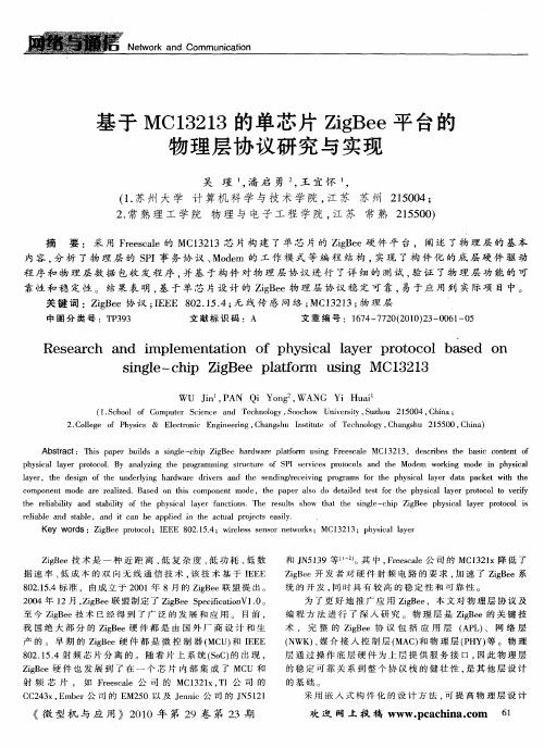
基于MC13213的单芯片ZigBee平台的物理层协议研究与实现吴瑾1,潘启勇2,王宜怀1,(1.苏州大学计算机科学与技术学院,江苏苏州215004;2.常熟理工学院物理与电子工程学院,江苏常熟215500)摘要:采用Freescale的MC13213芯片构建了单芯片的ZigBee硬件平台,阐述了物理层的基本内容,分析了物理层的SPI事务协议、Modem的工作模式等编程结构,实现了构件化的底层硬件驱动程序和物理层数据包收发程序,并基于构件对物理层协议进行了详细的测试,验证了物理层功能的可靠性和稳定性。
结果表明,基于单芯片设计的ZigBee物理层协议稳定可靠,易于应用到实际项目中。
关键词:ZigBee协议;IEEE802.15.4;无线传感网络;MC13213;物理层中图分类号:TP393文献标识码:A文章编号:1674-7720(2010)23-0061-05Research and implementation of physical layer protocol based on single-chip ZigBee platform using MC13213WU Jin1,PAN Qi Yong2,WANG Yi Huai1(1.School of Computer Science and Technology,Soochow University,Suzhou215004,China;2.College of Physics&Electronic Engineering,Changshu Institute of Technology,Changshu215500,China)Abstract:This paper builds a single-chip ZigBee hardware platform using Freescale MC13213,describes the basic content of physical layer protocol.By analyzing the programming structure of SPI services protocols and the Modem working mode in physical layer,the design of the underlying hardware drivers and the sending/receiving programs for the physical layer data packet with the component mode are realized.Based on this component mode,the paper also do detailed test for the physical layer protocol to verify the reliability and stability of the physical layer functions.The results show that the single-chip ZigBee physical layer protocol is reliable and stable,and it can be applied in the actual projects easily.Key words:ZigBee protocol;IEEE802.15.4;wireless sensor networks;MC13213;physical layerZigBee技术是一种近距离、低复杂度、低功耗、低数据速率、低成本的双向无线通信技术,该技术基于IEEE 802.15.4标准,由成立于2001年8月的ZigBee联盟提出。
2004年12月,ZigBee联盟制定了ZigBee SpecificationV1.0。
至今ZigBee技术已经得到了广泛的发展和应用。
目前,我国绝大部分的ZigBee硬件都是由国外厂商设计和生产的。
早期的ZigBee硬件都是微控制器(MCU)和IEEE 802.15.4射频芯片分离的。
随着片上系统(SoC)的出现,ZigBee硬件也发展到了在一个芯片内部集成了MCU和射频芯片,如Freescale公司的MC1321x,TI公司的CC243x,Ember公司的EM250以及Jennic公司的JN5121和JN5139等[1-2]。
其中,Freescale公司的MC1321x降低了ZigBee开发者对硬件射频电路的要求,加速了ZigBee系统的开发,同时具有较高的稳定性和可靠性。
为了更好地推广应用ZigBee,本文对物理层协议及编程方法进行了深入研究。
物理层是ZigBee的关键技术,完整的ZigBee协议包括应用层(APL)、网络层(NWK)、媒介接入控制层(MAC)和物理层(PHY)等。
物理层通过操作底层硬件为上层提供服务接口,因此物理层的稳定可靠关系到整个协议栈的健壮性,是其他层设计的基础。
采用嵌入式构件化的设计方法,可提高物理层设计的可移植性和可重用性,目前很少有人做这方面的工作。
本文采用射频片上系统(SoC)———MC13213设计了一个较通用的单芯片ZigBee硬件平台,分析和实现了ZigBee协议物理层,按照构件化的方法进行设计,并对构件进行了详细的测试,这不仅为基于物理层的简单应用提供了方法,而且为后续的MAC层的应用打下了基础。
1ZigBee物理层功能概述ZigBee工作在免申请的工业科学医疗频段。
IEEE 802.15.4标准中定义了两个可用的物理层:基于2.4GHz 频段的“短距离”实现和基于868/915MHz频段的“长距离”实现,两者都使用直接序列扩频(DSSS)技术。
中国目前的ZigBee工作频段为2.4GHz。
ZigBee物理层通过射频固件和射频硬件为MAC层和物理无线信道之间提供了服务接入点SAP(Service Access Point)。
IEEE802.15.4定义的物理层参考模型如图1所示。
其中PD-SAP(PHY Data Service Access Point)是物理层提供给MAC层的数据服务接口,PLME-SAP (Physical Layer Management Entity-Service Access Point)是物理层提供给MAC层的管理服务接口,RF-SAP是由底层无线射频驱动程序提供给物理层的接口。
物理层主要完成以下工作:激活和禁用射频收发器,对信道进行能量检测ED(Energy Detect),提供所接收数据包的链路质量指示LQI(Link Quality Indication),空闲信道评估CCA(Clear Channel Assessment),信道频率选择,数据发送和接收等。
2MC13213单芯片ZigBee物理层编程结构Freescale公司推出的单芯片ZigBee解决方案———MC13213采用SoC技术,在9mm×9mm的LGA封装内集成了HCS08MCU和遵循IEEE802.15.4标准的第二代无线射频收发器MC1320x[3-4](后文中将用MCU和Modem 分别代表MCU模块和射频收发器模块)。
具有4KB的RAM、60KB的Flash,1个串行外设接口(SPI),2个异步串行通信接口(SCI),1个键盘中断模块(KBI),2个定时器/脉宽调制TPM(Timer/PWM)模块,1个8通道10位的模数转换器(ADC),以及多达32个的GPIO口等[5]。
Modem内部已经集成了功率放大器PA(Power Amplifier)、低噪声放大器LNA(Low Noise Amplifier)和收/发开关(T/R switch),这在很大程度上降低了系统成本和射频电路的设计难度。
2.1Modem与MCU的交互方式Modem可以通过SPI接口、IRQ中断请求以及几个状态和控制信号与主控MCU实现交互,如图2所示。
SPI命令通道是Modem与MCU之间的主要交互方式,使用标准的4线SPI进行通信。
MCU通过SPI命令结构可以读/写Modem的寄存器内容、设置Modem的初始化参数、读取Modem的状态和控制信息。
IRQ中断为Modem提供了一种通知MCU有关Modem内部所发生事件的方法,这样就免除了MCU一直轮询Modem,降低了MCU的运行开销。
ATTN用来把Modem从低功耗模式唤醒,RXTXEN用来允许Modem的发送、接收和CCA等操作。
GPIO1引脚反映了Modem收发机是否忙,GPIO2引脚可以反映所接收数据包的循环冗余校验CRC(Cyclical Redundancy Check)是否有效或者反映CCA的结果[6]。
2.2Modem的SPI事务操作SPI事务是在标准SPI协议基础上实现的一个扩展SPI协议。
由于Modem中的寄存器和RAM大小都配置为16bit即一个字(word)的宽度,所以它规定了每次SPI 事务过程必须由1B的头(header)和2×N B的载荷(payload)组成,每个字节对应一个SPI脉冲(SPI burst),其中1≤N≤64,且为整数,代表每个SPI事务中所包含的字(word)数,当N=1时,称为SPI单次事务(SPI singular transaction);其他情况称为SPI循环事务(SPI recursive transaction)。
header的最高位为R/W位,表示操作类型是读还是写;header的低6位是寄存器地址,表示了SPI操作的64个可能的寄存器地址(注意,有一部分寄存器没有实现)。
2.3Modem的数据传输模式Modem定义了两种数据传输模式:Stream模式和Packet模式。
在Stream模式中,数据的发送和接收是逐字(word-by-word)处理的。
而在Packet模式中,发送时,发送方先将待发送数据缓存在Modem的发送缓冲区(TX RAM)中,然后再发送;接收时,接收方先在接收缓冲区(RX RAM)中缓存收到的整个数据包,然后再通知MCU来读取。
虽然Packet模式下数据的接收有稍许延迟,但其降低了对MCU的资源要求[7],在本协议栈实现过程中使用这种数据传输模式。
3物理层构件设计基于MC13213单芯片的ZigBee平台实现物理层协议构件程序的设计,首先必须编写底层硬件驱动程序,然后设置Modem的运行方式,再进行数据包收发程序的设计等。
3.1底层硬件驱动程序的实现硬件驱动程序介于底层硬件和ZigBee协议栈之间,可以使得运行于硬件之上的ZigBee协议栈更易于维护和移植。