
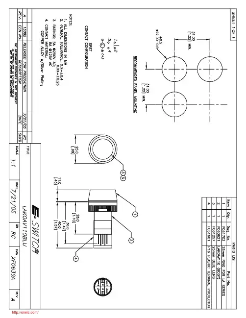
LAKOAV110BLU;中文规格书,Datasheet资料
- 格式:pdf
- 大小:51.31 KB
- 文档页数:2

®80i-110sAC/DC Current ProbeInstruction SheetIntroducing The Current Probe•The Fluke 80i-110s is a clamp-on AC/DC Current Probe that reproduces current waveforms found in modern commercial and industrial power distribution systems. The probe's performance is optimized for accurate reproduction of currents at linefrequency and up to the 50th harmonic waveform. The 80i-110s is also compatible with any instrument capable of millivoltmeasurements. The Current Probe (shown in Figure 1) provides the following benefits:•Accurate AC, DC and AC+DC current measurements for Electrical, Electronic and Automotive applications.•Shielded for high noise immunity around electronic motor drives and ignition systems.•Wide measurement range from 50 milliamps to 100 amps, useful to 10 milliamps.•Jaw shaped for easy access to cramped spaces.•Safety-designed 600 volt insuIated BNC - compatible with Fluke ScopeMeter® t est tools, Power Harmonic analyzers, andoscilloscopes.•Selectable output of 10 millivolts per 1 amp for the 100 A range,and 100 millivolts per 1 amp for the 10 A range.Figure 1. 80i-110s AC/DC Current ProbeUnpackingThe following items should be included in your Current Probe box: •AC/DC Current Probe, 80i-110s•Instruction Sheet (this sheet)•9 volt Battery, type IEC 6LR61Check the contents of the shipping box for completeness. If something in the box has been damaged or missing, contact your distributor or the nearest FLUKE sales or service office immediately. Installing The BatteryWarningTo avoid electrical shock, unclamp the current probefrom any conductor, and disconnect the scopemetertest tool or any other measurement device beforeinstalling or replacing the battery.At first use, remember to install the battery. Referring to Figure 2,use the following procedure to install the battery:1.Be sure that you have unclamped the Current Probe from anyconductor and have disconnected the ScopeMeter test tool orany other measurement device.2.Be sure that the Current Probe is in the OFF position.3.Locate the battery cover on the handle. (see Figure 2.) Loosenthe screw with a flat-blade screwdriver.4.Slide the battery cover away from the Current Probe.5.Install the battery (IEC 6LR61) as shown in Figure 2. Arrangethe battery leads so that they will not be pinched between thehandle bottom and the battery cover.6.Reinstall the battery cover and secure the screw.Figure 2. Installing the BatteryRead First: Safety Informationfollow these instructions:•Read the operating instructions before use and follow all safetyinstructions.•Use the Current Probe only as specified in the operatinginstructions, otherwise the current probe's safety features maynot protect you.•Adhere to local and national safety codes. Individual protectiveequipment must be used to prevent shock and arc blast injurywhere hazardous live conductors are exposed.•Do not hold the Current Probe anywhere beyond the tactileindicator, see Figure 1.•Before each use, inspect the Current Probe. Look for cracks ormissing portions of the Current Probe housing or output cableinsulation. Also look for loose or weakened components. Payparticular attention to the insulation surrounding the jaws.•Check the magnetic mating surfaces of the Current Probe jaws;these should be free of dust, dirt, rust and other foreign matter.•Never use the Current Probe on a circuit with voltages higherthan 600 V CAT II or 300 V CAT III.−CAT II equipment is designed to protect against transientsin circuits directly connected to the low-voltage installation,such as household appliances, portable tools and similarequipment.−CAT III equipment is designed to protect against transientsin equipment in fixed equipment installations, such asdistribution panels, feeders and short branch circuits, andlighting systems in large buildings.•Use extreme caution when working around bare conductors orbus bars. Contact with the conductor could result in electricshock.•Use caution when working with voltages above 60 V dc, 30 V acrms or 42 V ac peak. Such voltages pose a shock hazard.•Use of this equipment in a manner not specified herein mayimpair the protection provided by the equipment.Electrical SpecificationsAll Electrical Specifications are valid at a temperature of 23 °C± 3°C (73 °F ± 5 °F).Current Ranges: 0 to 10A dc or ac peak0 to 100A dc or ac peakOutput Signals: 10A range: 100 mV/A100A range: 10 mV/AWorking voltage (Probe jaws to Ground) &Floating Voltage (Output cable and connector toGround):600V ac rms on Measurement Category II (CAT II) & 300Vac rms on Measurement Category III (CAT III) circuits perEN/IEC 61010-1.Basic Accuracy (DC to 1kHz):Error (after zero check)InputCurrent (DCor AC peak)100 mV/A 10 mV/A0 to 10A0 to 40A40 to 80A80 to 100A<3% of reading +50 mA----<4% of reading +50 mA<12% of reading +50 mA<15% of readingExtended Accuracy:For other frequencies, refer to the appropriate input current rangeand add the error listed below to the "Basic Accuracy" error.Additional ErrorFrequency100 mV/A 10 mV/A1 to 5 kHz5 to 20 kHz>20 kHz3%12%not specified3%12%not specifiedInput Load Impedance (of host instrument):>1MΩin parallel with up to 100 pFUseful Bandwidth (-3 dB): 0 to 100 kHzRise or Fall Time: <4 µsecOutput noise level: 10 mV/A typ. 480 µV pk-pk100 mV/A typ. 3 mV pk-pkMax. non destructive current: 0 to 2 kHz 140A peak2 to 10 kHz 110A peak10 to 20 kHz 70 A peak20 to 50 kHz 30A peak50 to 100 kHz 20A peakTemperature coefficient:2000ppm/°C max. for temperature from 0 to 50 °C (32 to 132 °F)General SpecificationsDimensions: 67 x 231 x 36 mm (2.6 x 9.1 x 1.4 inches)Weight: 330g (11.6 oz.), battery includedOutput Cable: 1.6 meters (63 inches)Maximum Conductor Size: 11.8 mm (.46 inch)Maximum Jaw Opening: 12.5 mm (.49 inch)Temperature: operating: 0 to 50°C (32 to 122°F)nonoperating: -30 to 70°C (-22 to 158°F)Relative Humidity (Operating): 0 to 85% (0 to 35°C; 32 to 95°F )0 to 45% (35 to 50°C; 95 to 122°F)Altitude:operating: 0 to 2000 meters (0 to 6560 feet)nonoperating: 0 to 12000 meters (0 to 40000 feet)Demagnetize Probe: Open and close probe jaws several timesSafety SpecificationsComplies with American Industry standards UL61010B-1 &UL61010B-2-032, Canadian standards CAN/CSA C22.2 No. 61010-1 (2004) & No. 61010-2-032 (2004) and European standardsEN/IEC 61010-1 2nd Edition & EN/IEC 61010- 02-032.Measurement Category Rating: 300V CAT III & 600 V CAT II,pollution degree 2.This product is in conformity with Electromagnetic CompatibilityDirective 89/336/EEC, and low Voltage Directive 73/23/EEC.européenne”.Battery InformationBattery: 9 volt, IEC 6LR61Consumption: 8.6 mA typical12 mA maximumService life: 55 hours typical, when Alkaline IEC 6LR61 is used40 hours minimum, when Alkaline IEC 6LR61 is usedBattery indicator (ON):GreenLEDdims when battery voltage is below 6.5VTo avoid false readings which could cause injury,replace battery as soon as the Battery Indicator greenLED dims.Overload indicator (OL):Red LED indicates that waveform or impulse is out of rangeInstrument CompatibilityThe 80i-110s is compatible with any Fluke ScopeMeter test tool,Power Harmonics Analyzer, Oscilloscope, Multimeter, or othervoltage measurement device that has the following features:•BNC input connector. A BNC-to-banana adapter (orderPM9081/001 from Fluke) can also be used with standard inputson a digital multimeter (DMM).•Input accuracy of 2% or better to take full advantage of theaccuracy of the probe.•Input impedance of greater than or equal to 1 MΩ i n parallel witha maximum of 100 pF.• A passband of more than four times the frequency of thewaveform to be measured.Using The Current ProbeTo use the Current Probe, follow these instructions:1.Connect the 80i-110s Current Probe to the desired input on themeasuring instrument. When the ScopeMeter test tool or anoscilloscope is used, it must have DC coupled input. When youare using a digital multimeter, use the BNC-to- banana adapter(PM9081/001) to connect the probe to the input.2.On the Current Probe, select the least sensitive range (10mV/A). Ensure that the green ON-indicator lights. See Figure 4for selector switch and green On indicator locations.3.On the Current Probe, rotate the ZERO thumbwheel to adjustthe probe reading to zero. See Figure 4 for the ZERO rotaryknob location.4.Select the appropriate probe sensitivity on your ScopeMetertest tool or oscilloscope.5.Clamp the Current Probe around the conductor; be sure thatthe arrow marked on the jaw of the Current Probe pointstoward the correct orientation. (see Figure 3.)4822 872 30777October 2005© 2005 Fluke Corporation.All rights reserved.Printed in the Netherlands.All product names are trademarksof their respective companies.ST7706Figure 3. Orientation of the Current Probe6.Observe the current value or waveform on your display or thecurrent value readout on the multimeter.7.On the ScopeMeter test tool, adjust the vertical range knoband time division knob for the best display.8.If the red OL-indicator lights, the Current Probe is in overloadmode.9.At completion, be sure to set the range selection switch to OFFagain. A measuring setup using the Current Probe and aScopeMeter test tool is shown in Figure 4.Figure 4. Measuring Setup Measurement considerationsObserve the following guidelines for positioning the Current Probe Jaws:•Center the conductor inside the probe jaws.•Make sure the probe is perpendicular to the conductor.•Make sure that the arrow marked on the jaw of the Current Probe points toward the correct direction.Observe the following guidelines when making measurements:•If possible, avoid measurements close to other current-carrying conductors.•On the Current Probe, the 100 mV/A range offers the best accuracy.MaintenanceBefore each use, assure continued safety by inspecting the probe. Look for cracks or missing portions of the probe housing and output cable insulating cover and for loose or weakened components. Pay particular attention to the insulation surrounding the probe jaws. If a probe fails this inspection, tape it shut to prevent unintended operation. To check probe performance, complete the "Performance Verification" procedure.WarningThese servicing instructions are for use by qualifiedpersonnel only. To avoid electric shock, do notperform any servicing procedures unless you arequalified to do so. Read the information titled "SafetyInformation" at the beginning of this instruction sheetbefore proceeding.Repairs or servicing not covered in this Users Manual should be performed only at a Fluke Service Center. A probe under warranty will be promptly repaired or replaced (at Fluke's discretion) and returned at no charge. Cleaning and storagePeriodically wipe the case with a damp cloth and detergent; do notuse abrasives or solvents. Open the jaws and wipe the magneticpole pieces with a lightly oiled cloth. Do not allow rust or corrosionto form on the magnetic core ends. If the probe is not used forperiods of longer than 60 days, the battery should be removed andstored separately.Performance verificationVerify probe accuracy with the test setup shown in Figure 5.Required test equipment is defined in Table 1. Toroid coilconstruction is illustrated in Figure 6.Do the following to verify the probe accuracy:1.Set up Connection.2.Make the checks called for in Table 2 (100 mV/A).3.Make the checks called for in Table 3 (10 mV/A).Table 1. Required Test EquipmentREQUIRED RECOMMENDED MODELAC/DC CalibratorDigital Multimeter (DMM)Small insulated screwdriverBanana-to-BNC Adapter10-Turn Toroid CoilFluke Model 5520AFluke Model 45SpectrolFluke Model PM9081/001(see Figure 6.)CAL5520A_45Figure 5. Performance Test and Calibration Setup10.5CM(4INCH)10TURNS WOUND ONCYLINDRICAL FORM USING10-GAUGE MAGNET WIRE.REMOVE FORM AND TAPECOIL TOGETHER MAKINGSURE10WIRES ARE TAPED.TAPEFAN OUT COIL TO APPROX.270°WITH SPACING5CM(2INCH)USINGTAPE TO MAINTAIN COIL SHAPE.Figure 6. Toroid Coil ConstructionTable 2. Performance Test PointsCurrent range 0 to 10A (100 mV/A)DC Measurement:5520ASETTINGSDC AMPSMEASUREDLOW LIMITOUTPUTHIGH LIMITOUTPUT0.1A0.5A0.9A1A5A9A92 mV480 mV868 mV108 mV520 mV932 mVAC Measurement:5520ASETTINGSRMS AMPSMEASUREDLOW LIMITOUTPUTHIGH LIMITOUTPUT0.1A, 60 Hz0.3A, 400 Hz0.5A, 2 kHz0.6A, 4 kHz1A3A5A6A92 mV286 mV465 mV559 mV108 mV314 mV535 mV641 mVTable 3. Performance Test PointsCurrent Range 0 to 100A (10 mV/A)DC Measurement:5520ASETTINGSDC AMPSMEASUREDLOW LIMITOUTPUTHIGH LIMITOUTPUT1A3A5A7A9A10A30A50A70A90A95.5 mV287.5 mV439.5 mV615.5 mV765.0 mV104.5 mV312.5 mV560.5 mV784.5 mV1035.0 mVAC Measurement:5520ASETTINGSRMS AMPSMEASUREDLOW LIMITOUTPUTHIGH LIMITOUTPUT1A, 5 kHz2A, 1 kHz3A, 400 Hz5A, 400 Hz7A, 60 Hz10A20A30A50A70A92.5 mV185.5 mV287.5 mV439.5 mV595.0 mV107.5 mV214.5 mV312.5 mV560.5 mV805.0 mVIf Your Current Probe Does Not WorkIf the 80i-110s does not perform properly, use the following steps tohelp isolate the problem:1.Test the battery: be sure that the green ON-indicator lightswhen you select the 10 mV/A range or the 100 mV/A range.2.Inspect the jaw mating surface for cleanliness. If any foreignmaterial is present, the jaws will not close properly and errorswill result.3.Verify that the probe is zeroed properly. For zeroing be surethat the ScopeMeter test tool or oscilloscope is DC-coupled.4.Verify that the function selection on the ScopeMeter test tool oroscilloscope is correct, i.e., the display vertical resolution is nottoo low or too high.Replacement PartsTo order replacement parts in the USA, call 1-800-526-4731. Toorder outside the USA, contact the nearest Service Center. Use thefollowing part numbers:Description Part Number9 Volt Battery (IEC 6LR61)Battery CoverInstruction Sheet4822 138 101165322 447 923224822 872 30777Order Fluke Part PM9081/001 BNC-to-Banana Adapter to use theCurrent Probe with a digital multimeter.LIMITED WARRANTY & LIMITATION OF LIABILITYThis Fluke product will be free from defects in material andworkmanship for one year from the date of purchase. This warrantydoes not cover fuses, disposable batteries or damage fromaccident, neglect, misuse or abnormal conditions of operation orhandling. Resellers are not authorized to extend any other warrantyon Fluke’s behalf. To obtain service during the warranty period,send your defective product to the nearest Fluke Authorized ServiceCenter with a description of the problem.THIS WARRANTY IS YOUR ONLY REMEDY. NO OTHERWARRANTIES, SUCH AS FITNESS FOR A PARTICULARPURPOSE, ARE EXPRESSED OR IMPLIED. FLUKE IS NOTLIABLE FOR ANY SPECIAL, INDIRECT, INCIDENTAL ORCONSEQUENTIAL DAMAGES OR LOSSES, ARISING FROM ANYCAUSE OR THEORY.Since some states or countries do not allow the exclusion orlimitation of an implied warranty or of incidental or consequentialdamages, this limitation of liability may not apply to you.Fluke Corporation Fluke Industrial B.V.P.O. Box 9090 P.O. Box 90Everett WA 7600 AB Almelo98206-9090, USA The NetherlandsSERVICE CENTERSTo locate an authorized service center,visit us on the World Wide Web:or call Fluke using any of the phone numbers listed below:+1-888-993-5853 in U.S.A. and Canada+31-40-267-5200 in Europe+1-425-446-5500 from other countries。

4N E x t G E N E R a t i O NB U S B A R m O d u L E!VSPL/ENG/SC/106-Rev00Dimensions in mmsales @ THIS DATASHEET IS APPLICABLE FOR: elDora VSP.60.aaa.03 (aaa=250-270)CautiON: READ SAFETY AND INSTALLATION MANUAL BEFORE USING THE PRODUCT.Specifications included in this datasheet are subject to change without notice. Electrical data without guarantee. Please confirm your exact requirement with the company representative while placing your order.Performance WarrantyIV CurvesDS-60-P-4BB-E-R0135,3992956.44-7.5 × 7.5 / 2DRAIN HOLEJUNCTION BOX LABEL1000+–2–4⦰GROUNDINGHOLE8-6.5 × 10¹⁶-8 × 3.5VENT HOLEINSTALLINGHOLESIDE VIEWBACK VIEWSECTIONAL VIEW OF AL-PROFILE35.325.411.4164013608601000 W/m 2700 W/m 2400 W/m 2200 W/m 2100 W/m 2987654321C u r r e n t (A )VoltAge (V)0 5 10 15 20 25 30 35 40100%90%80%70%60%1 YEAR27 YEARS1 year: 97.5%27 years: 80.1%Electrical Data 1 All data refers to STC (AM 1.5, 1000 W/m 2, 25 °C)Peak Power P max (Wp)250252.5255257.5260262.5265267.5270maximum Voltage V mpp (V)30.4930.5430.6230.7330.8430.8930.9230.9831.03maximum current I mpp (a)8.208.278.338.388.438.508.578.648.704open circuit Voltage V oc (V)37.4437.5137.5937.7737.9537.9038.1238.238.28Short circuit current I sc (a)8.758.808.848.888.938.989.039.099.15module efficiency (%)15.3715.5215.6715.8315.9816.1416.2916.4416.601) STC: 1000 W/m 2 irradiance, 25°C cell temperature, AM 1.5g spectrum according to EN 60904-3.Average relative efficiency reduction of 5% at 200 W/m 2 according to EN 60904-1.Electrical Parameters at NOCT 2Power (W)185.62187.25188.88191.65192.79193.49194.69196.02197.77V @P max (V)27.6527.6927.7227.7727.8227.8627.9027.9528.01I @P max (a) 6.72 6.77 6.82 6.87 6.93 6.96 6.987.027.06V oc (V)35.1635.2535.3535.3635.3635.4235.4835.5335.59I sc (a)7.067.117.167.207.247.317.377.437.492) NOCT irradiance 800 W/m 2, ambient temperature 20°C, wind speed 1 m/secTemperature Coefficients (Tc) permissible operating conditionsTc of open circuit Voltage (β)-0.31%/°CTc of Short circuit current (α)0.058%/°C Tc of Power (γ)-0.41%/°C maximum System Voltage 1000 V nocT45°C ± 2°C Temperature range-40°C to + 85°CMechanical Datalength × Width × Height 1640 × mm × 992 mm × 36 mm Weight 18 kgJunction Box IP67, 3 bypass diodescable & connectors 1000 mm length cables,SOLARLOK PV4 connectors (MC4 compatible)application class Class A (Safety class II)Superstrate High transmission low iron tempered glass, AR coated cells60 polycrystalline solar cells, 4 bus bars cell encapsulant EVA (Ethylene Vinyl Acetate)Back Sheet Composite filmframeAnodized aluminium frame with twin wall profile mechanical load Test 5400 Pa maximum Series fuse rating15 AWarranty and CertificationsProduct Warranty**10 yearsPerformance Warranty**Linear power warranty for 27 years with 2.5% for 1st year degradation and 0.67% from year 2 to year 27approvals and certificatesIEC 61215 Ed2*, IEC 61730*, IEC 61701*, IEC 62716*, CE*, MCS*, PV Cycle, IEC 62804*, CEC (Australia)*Packaging InformationQuantity /Pallet28Pallets/container (40'Hc)28Quantity/container (40'Hc)784* All (*) certifications under progress.** Refer to Vikram Solar’s warranty document for terms and conditions.TECHNICAL DATAELDORA PRIME SERIES。

Features• 3.5dB Typical Noise Figure • 12.5dB Typical Gain• 12dBm Saturated Output Power • 12dB Input/Output Return Loss Typical • 0.5-6GHz Frequency Bandwidth • +8 Volts Single Bias Supply• DC Decoupled RF Input and Output• Chip Size : 1.62mm X1.62mm (.064”X.064”)• Chip Thickness : 100µm• Pad Dimension : 100µm 2DescriptionThe Filtronic LMA110B is a GaAs monolithic distributive amplifier which operates from 0.5 to 8 GHz. This amplifier produces a typical gain of 12.5dB with a noise figure of 3.5dB. The LMA110B is suitable for wide-band low noise gain block, EW and commercial PCN applications. DC decoupled input and output RF port. Ground is provided to the circuitry through vias to the backside metallization.Electrical Specifications at T a =25°C(V DD =+8.0V, Zin=Zout=50Ω)Absolute Maximum RatingsNotes :1. This GaAs MMIC is susceptible to damage from Electrostatic Discharge. Proper precautions should be used when handling these devices.2. Specifications subject to change without notice.DSS 005 WDLimit Symbol ParameterTest Conditions Min.Typ.Max.Units BW Operating Bandwidth 0.58GHz S21Small Signal Gain V D =8V, Vg1=Vg2=8V1112.5dB Ids Drain Operating Current 6085110mA ∆S21Small Signal Gain Flatness±1±1.5dB NF Noise Figure @ 50% Idss3.54.5dB RLin Input Return Loss -10-8dB RLout Output Return Loss -10-8dB S12Reverse Isolation-30dB P-1dB1-dB Gain Compression Power810dBmSymbol Parameter /Conditions Min.Max.Units Vdd Drain Supply Voltage 13Volts Idd Total Drain Current 110mA Pin RF Input Power 24dBm Pt Power Dissipation1.5W Tch Operating Channel Temperature150°C Tstg Storage Temperature -65165°C Tmax.Max. Assembly Temp.(1 min. max.)300°CAssembly DiagramSIMPLE BIAS SCHEMENotes:1.) Recommended lead bond technique is thermocompression wedge bonding with 0.001” (25µm) diameter wire. The bond tool force shall be 35-38 gram. Bonding stage temperature shall be 230-240°C, heated tool (150-160°C) is recommended. Ultrasonic bonding is not recommended.2.) The recommended die attach is Ablebond silver epoxy, the stabilize bake temperature is set at 150°C for 45 minutes.3.) Bond on bond or stitch bond acceptable.4.) Conductor over conductor acceptable. Conductors must not short.DSS 005 WDAssembly DiagramOPTIMUM BIAS SCHEMENotes:1.) Recommended lead bond technique is thermocompression wedge bonding with 0.001” (25µm) diameter wire. The bond tool force shall be 35-38 gram. Bonding stage temperature shall be 230-240°C, heated tool (150-160°C) is recommended. Ultrasonic bonding is not recommended.2.) The recommended die attach is Ablebond silver epoxy, the stabilize bake temperature is set at 150°C for 45 minutes.3.) Bond on bond or stitch bond acceptable.4.) Conductor over conductor acceptable. Conductors must not short.DSS 005 WDMechanical OutlineNotes:1.)Unless Otherwise specified.2.) All units are in micron (µm).3.) All bond pads are 100 X 100 µm2.4.) Bias pad (V DD) size is 100 X 121.5 µm2.DSS 005 WD。

VIAVI Solutions The OSA-110 Series is the compact VIAVI Solutions™ optical spectrum analyzer(OSA) modules with unmatched size, weight, and performance, which make it idealfor field use. Housed inside the One Advisor 800 Fiber platform, it offers the mostcompact high performance full-band OSA solution on the market.The OSA-110 Series is suitable for all optical coarse wavelength divisionmultiplexing (CWDM) and dense wavelength-division multiplexing (DWDM)networks down to 33 GHz channel spacing. In addition to standard featuresprovided by the OSA-110M, the OSA-110H integrates a high-power measurementcapability, making it the ideal tool for cable operators. The OSA-110R includes thewell-known VIAVI in-band measurement technique to measure the true OSNR inROADM-based networks and in 40 G systems with overlapping spectra.The combination of high optical resolution with full-band measurement capabilitymakes the OSA-110 Series ideal for testing power, wavelength, OSNR, and driftduring provisioning, maintenance, and upgrades of WDM systems., access, and mobile backhaulVerifying high-speed 40/100 G interfacesProvisioning and troubleshooting ROADMnetworksData SheetVIAVIOSA-110M/110H/110R CompactFull-Band OSAsFor OneAdvisor 800 Fiber platformTest xWDM Networks with a Compact, Full-Band OpticalSpectrum Analyzer1© 2022 VIAVI Solutions Inc.Product specifications and descriptions in this document are subject to change without notice.Patented as described at /patentsosa110-h-r-ona800f-fop-nse-ae30193456 900 0722Contact Us +1 844 GO VIAVI (+1 844 468 4284)To reach the VIAVI office nearest you, visit /contacts.。