Mastercam数控编程实例介绍
- 格式:pdf
- 大小:1.60 MB
- 文档页数:19
mastercam车床圆球编程实例-概述说明以及解释1.引言1.1 概述Mastercam是一款广泛应用于数控编程和加工领域的软件,其强大的功能和易用性受到许多制造业人员的青睐。
在数控车床加工中,圆球编程是一项常见且重要的任务,用于加工如轴承座、阀门座等零部件。
本文将介绍如何利用Mastercam软件进行车床圆球编程,通过详细的步骤和实例演示,帮助读者更好地理解和掌握这一技术。
通过本文的学习,读者将能够快速高效地进行车床圆球编程,提高加工效率和质量。
1.2 文章结构文章结构部分的内容如下:文章结构部分主要介绍了本篇文章的组织结构,包括引言、正文和结论三个部分。
在引言部分,将会概述本文的主题内容,说明文章的结构和目的。
正文部分将分为Mastercam软件介绍、车床圆球编程步骤和编程实例演示三个小节,详细介绍Mastercam软件的特点和使用方法,以及车床圆球编程的具体步骤和实例演示。
结论部分将总结编程要点,展望该技术的应用前景,并给出一些结语。
整篇文章结构清晰,层次分明,使读者能够更好地理解和掌握Mastercam车床圆球编程的知识。
1.3 目的本文的主要目的是通过对Mastercam车床圆球编程实例的介绍和演示,帮助读者了解和掌握Mastercam软件的使用技巧,特别是在车床圆球编程方面的操作步骤和注意事项。
通过具体的编程实例,读者可以深入了解Mastercam软件的功能和运用,从而提升自己在数控编程领域的技能水平。
同时,本文也旨在激发读者对数控编程的兴趣,帮助他们在实际工作中更加灵活和高效地应用Mastercam软件,提升生产效率和质量水平。
希望通过本文的介绍和演示,读者能够更加深入地了解Mastercam 软件在车床圆球编程方面的应用,为其日后的工作和学习提供有益的参考和支持。
2.正文2.1 Mastercam软件介绍Mastercam是一款专业的CAD/CAM软件,是美国CNC Software Inc.公司研发的数控编程软件。

一、实验目的1、了解CAD/CAM及数控加工的基本原理及方法;2、熟悉网络化设计与制造的基本原理及方法;3、掌握零件从CAD、CAM到数控加工的完整过程。
二、实验内容选用Mastercam 8.0和其它CAD软件,实现一个复杂零件从计算机辅助设计到数控加工的完整过程,并完成实验报告。
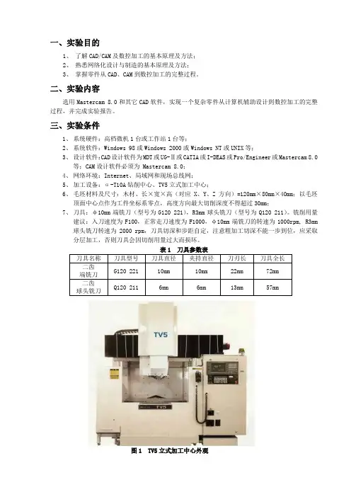
三、实验条件1、系统硬件:高档微机1台或工作站1台等;2、系统软件:Windows 98或Windows 2000或Windows NT或UNIX等;3、设计软件:CAD设计软件为MDT或UG-Ⅱ或CATIA或I-DEAS或Pro/Engineer或Mastercam 8.0等;CAM设计软件必须为 Mastercam 8.0;4、网络环境:Internet、局域网和现场总线网;5、加工设备:α-T10A钻削中心、TV5立式加工中心;6、毛坯材料及尺寸:木材、长×宽×高(对应X、Y、Z方向)=120mm×80mm×40mm;以毛坯顶面中心点作为工件坐标系零点,高度方向最大切削深度不得超过30mm;7、刀具:φ10mm端铣刀(型号为G120 221),R3mm球头铣刀(型号为Q120 211)。
铣削用量建议:入刀速度为F100,正常走刀速度为F1000,φ10mm端铣刀的转速为1000rpm, R3mm 球头铣刀转速为2000 rpm,刀具切深和步距自定,注意粗加工切深不能一步到位,应采取分层加工,否则刀具会因切削用量过大而损坏。
表1 刀具参数表图1 TV5立式加工中心外观图2 α-T10A钻削加工中心外观四、实验过程1、用Mastercam 8.0或其它CAD软件完成型面或型腔零件的建模,通常要用到实体造型和曲面造型功能。
若用其它CAD软件建模,则应将零件模型转化成Mastercam 8.0能读取的文件格式存盘(建议用IGES格式);2、要求统一选用Mastercam 8.0的MILL模块刀具生成路径和NC程序;1)加工工艺规划:粗加工、半精加工、精加工,中间还需穿插清根工序;2)选取加工刀具并设置刀具参数;3)设定毛坯尺寸、材料以及工件坐标系;4)设置刀具加工形式和切削用量;5)编制刀具路径;6)加工过程仿真和修改参数。
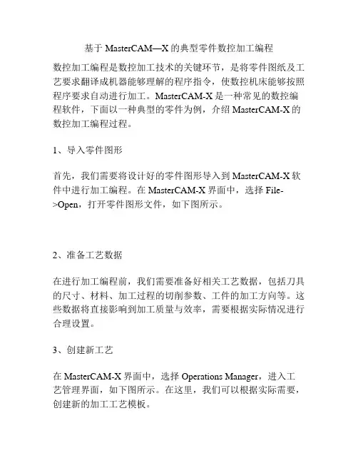
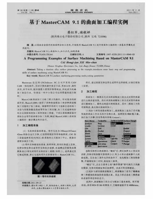
基于MasterCAM—X的典型零件数控加工编程数控加工编程是数控加工技术的关键环节,是将零件图纸及工艺要求翻译成机器能够理解的程序指令,使数控机床能够按照程序要求自动进行加工。
MasterCAM-X是一种常见的数控编程软件,下面以一种典型的零件为例,介绍MasterCAM-X的数控加工编程过程。
1、导入零件图形首先,我们需要将设计好的零件图形导入到MasterCAM-X软件中进行加工编程。
在MasterCAM-X界面中,选择File->Open,打开零件图形文件,如下图所示。
2、准备工艺数据在进行加工编程前,我们需要准备好相关工艺数据,包括刀具的尺寸、材料、加工过程的切削参数、工件的加工方向等。
这些数据将直接影响到加工质量与效率,需要根据实际情况进行合理设置。
3、创建新工艺在MasterCAM-X界面中,选择Operations Manager,进入工艺管理界面,如下图所示。
在这里,我们可以根据实际需要,创建新的加工工艺模板。
4、建立刀具库刀具是数控加工中重要的工具,可以直接影响到加工质量和效率。
在MasterCAM-X中,我们可以使用刀具库,快速方便地选择需要的刀具。
选择Tool Manager,进入刀具管理界面,如下图所示。
在刀具管理界面中,可以设置切削刀具的相关参数,包括刀具直径、长度、刀尖半径、速度、进给量等。
接着,在工艺管理界面中新增工艺步骤,将刀具库中的刀具与工艺进行绑定,实现自动化的刀具选择。
5、生成切削路径将刀具库中的刀具与零件图形进行绑定后,我们需要生成合理的切削路径。
在MasterCAM-X界面中,我们可以使用散集命令、多边形命令等方式,快速生成切削路径。
需要注意的是,在切削路径生成的过程中,需要充分考虑切削参数、加工方向、刀具的尺寸等因素,以实现高效、准确的加工质量。
6、生成NC代码生成NC代码是数控加工编程的最后一步,也是最重要的一步。
在MasterCAM-X界面中,选择操作模块Operations Manager,点击Generate Code,即可生成NC代码。
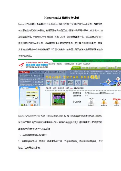
Mastercam9.1编程实例讲解MasterCAM8软件是美国CNC SoftWare.INC.所研制开发的CAD/CAM系统,是最经济有效率的全方位的软件系统。
包括美国在内的各工业大国皆一致采用本系统,作为设计、加工制造的标准。
MasterCAM8为全球PC级CAM,全球销售量第一名,是工业界及学校广泛采用的CAD/CAM系统,以美国和加拿大教育单位来说,共计有2500多所高中、专科大学院校使用此来作为机械制造及NC程式的制作,在中国大陆及台湾其业界及教育单位亦有领先之地位。
MasterCAM8分为四个系统:三维设计系统,铣床3D加工系统,车床\铣床复合系统,线切割\激光加工系统,由于本书作为模具专业CAM教学的特点,我们只介绍与模具设计密切相关的三维设计系统和铣床3D加工系统.一、三维设计系统:(CAD部分)1、完整的曲线功能:可设计、编辑复杂的二维、三维空间曲线。
还能生成方程曲线。
尺寸标注、注释等也很方便。
2、强大的曲面功能:采用NURBS、PARAMETRICS等数学模型,有十多种生成曲面方法。
还具有曲面修剪、曲面间等(变)半径倒圆角、倒角、曲面偏置、延伸等编辑功能。
3、崭新的实体功能:以PARASOLID为核心,倒圆角、抽壳、布尔运算、延伸、修剪等功能都很强。
4、可靠的数据交换功能,可转换的格式包括:IGES、SAT(ACIS SOLIDS)、DXF、CADL、VDA、STL、DWG、ASCII。
并可读取Parasolid、HPGL、CATIA、PRO/E、STEP等格式的数据文件。
二、铣床3D加工系统.(CAM部分)1、完整三维设计系统。
2、完整的铣床2D、2.5D加工系统。
3、多重曲面的粗加工及精加工。
4、等高线加工。
5、环绕等距加工。
6、平行式加工。
7、放射状加工。
8、插拉刀方式加工。
9、投影加工。
10、沿面加工。
11、浅平面及陡斜面加工。
12、G01可过滤为G02、G03并可程式过滤更平稳。
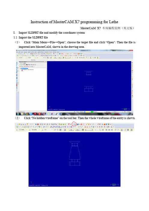
Instruction of MasterCAM X7 programming for LatheMasterCAM X7 车床编程范例(英文版)I.Import SLDPRT file and modify the coordinate system1.1Import the SLDPRT file(1)Click “Main Menu→File→Open”, choose the target file and cli ck “Open”. Then the file is imported into MasterCAM, shown in the drawing area.(2)Click “No hidden wireframe” on the tool bar. Then the whole wireframe of the entity is shown.(3)Press “F9” and “Alt+F9”. The coordinate system is then visible.(4)One can modify the viewing angle by pressing and dragging mouse wheel or by choosing viewing plane in “Gview” option at the bottom.1.2Modify the coordinate system(1)Click “Planes→Lathe diameter→+D +Z (WCS)”.(2)Click “Gview→Top(WCS)” and “WCS→Top WCS”.1.3Rotate and translate the entity as required(1)Select the whole entity, click “Xform Move to Origin” and then select the outside circle of the top of the candle holder. Then the center of the top circle of the holder is set to be the origin.(2)Set back to a Top Gview. Select the entity. Use the “Xform Rotate” tool to fix the center line of the entity on the x axis of the World Coordinate System which is indicated in the drawing area.In our case, the rotate angle is -90 degree.Then a standard view of the entity and coordinate system should be gotten.II.Turn the wireframe into profile2.1Set up another geometry level(1)Click “Level” in the bottom of the software.(2)Type “2” in the yellow input bar under “Number” in the “Main Level” section. Then click the green OK button. A new level 2 is created.2.2Turn wireframe to profile on level 2Click “Main Menu→Create→Turn Profile”, select the entity and press “ENTER” on the key board. Click the green OK button on the new window. The profile of the entity is created. A better vision can be achieved by hiding level1.2.3Hide level 1Click the “level” button in the bottom of the software. Click the two areas shown in the below with the indicated sequence. Then the “Visible” sign of level 1 is unchecked. Level 1 is hidden.III.Plan the toolpaths3.1Set up a machine group.Click “Main Menu→Lathe→Default”. A machine group is then set up in the Operation Manager.3.2Set the parameters of stock and chunk jaws(1)Click “Tool settings” in the Operations Manager to open the “Machine Group Properties”setting window. Then set the parameters as shown in the figures.(2)Click “Properties” button of Stock and Chunk Jaws. Set the parameter as shown below.3.3Plan the toolpath for facing(1)Click “Main Mune→Toolpaths→Face”. Click the green OK button. A setting window is shown. Set the parameters in the window as shown. Turn on the flood cooling in “Coolant” option.Left click the tool “R0.8 OD ROUGH RIGHT –80 DEG.”, right click it, choose “Edit tool”. Select “triangle” in the Shape section. Click green OK button.(2) Click “Face parameters” tab, set the parameters shown below. Then click “Lead in/Out”. Setthe parameters as shown. Click green OK button. The facing toolpath is then finished.3.4Plan the roughing toolpaths(1)Add two short lines on the profile as shown to avoid roughing process going into the grooving part and to leave some place for cutting off at the bottom.(2)Click “Main Menu→Toolpaths→Rough”. A chain selecting window is shown. Select the lines along the roughing surface line by line to select the chain.(3)Set the parameters as shown in the figure. Turn on the flood cooling in “coolant” option. Click the green OK button after setting. Then the roughing toolpath is generated.3.5Plan the grooving toolpaths(1)Click “Main Menu→Toolpaths→Groove”. Select “Chain” in the following “Grooving Options” window. Then a chain selecting window is shown. Select the lines along the surface of the design till the deep groove which will be made later for safety concerns. Click the green OK button when finishing the selection.(2)Select an “OD CUTOFF RIGHT” tool and set the parameters in Toolpath parameters” tab of “Lathe Groove (Chain) Properties” windows as shown below. Then right click on the tool icon, click “Edit tool” and set the parameters as shown.(3)Click the “Groove rough parameters” tab on the “Lathe Groove (Chain) Properties” window and set the parameters there as shown. Check the choosing boxed of “Peck Groove” and “Depth Cuts…” and set the parameters inside as shown.(4)Click the “Groove finish parameters” tab on the “Lathe Groove (Chain) Properties” window and uncheck “Finish” on the left top corner.3.6Plan the finishing toolpaths(1)Click “Main Menu→Toolpaths→Finish” to set up a right-hand finishing toolpath. Choose thesame chain as that in 3.4 (2). Set the parameters as shown below. Turn on the flood cooling in “coolant” option. Click all the green OK button after setting. A right-hand finishing toolpath is set.(2)Click “Main Menu→Toolpaths→Finish” to set up a left-hand finishing toolpath. The chosen chain is only the part which cannot be finished by the right-hand finishing as shown below.(3)Set the parameters as shown below. T urn on the flood cooling in “coolant” option. Click all the green OK button after setting. A right-hand finishing toolpath is set.3.7Plan the Grooving path(1)Click “Main Menu→Toolpaths→Groove” to start a grooving toolpath setting. Choose “3 lines”option to set the path in our case. The path is then chose as shown below. Press “ENTER” on the keyboard. Then the parameter setting window shows up.(2)Choose the same grooving tool as in 3.5 and set the toolpath parameters as shown. Set the flood coolant. Then right click the tool, click “Edit Tool”. Set the parameters of “Inserts”, then the “Holders”. Click green OK button. Choose the “Groove rough parameters” and “Groove finish parameters” tap separately in the Lathe Groove parameters window and set the para meters there.In the “Groove rough parameters”tab, remember to select “Peck Groove” and “Depth cuts…” and set the parameters inside. Click all the green OK button. The grooving path is then set.3.8Plan the drilling pathClick “Main Menu→Toolpaths→Drill” to start a drilling toolpath setting. Set the parameters in “Toolpath parameters” tab as below. Set up the flood coolant. Select a tool similar to “END MILL 15. DIA”. Left click the tool. Click “Edit Tool”, set the tool parameter as shown below. Click the OK button. Then set parameters in “Simple drill –no peck” tab.3.9Plan the boring path(1)Draw a line connecting the origin to the center point of the internal circle of the holder. Then translate it with D=15.(2)Then break the line of the inner circle’s radius into two parts using the new drawn line with the “Break Two pieces” button.(3)Click “Main Menu→Toolpaths→Rough” to start a roughing toolpath setting. Select the toolpath as shown below. Then a parameter setting window shows up.(4)Select a tool similar to “ROUGH MIN 16. DIA. –80 DEG.”. Set the parameters in “Toolpath parameter” as shown below. Turn on the flood cooling. Then left click the tool, select “Edit tool”and change the “Corner Radius” to 08 in the “Inserts” tab. Then click OK button, back to the “Lathe Rough Properties” window.(5)Set parameters in “Rough Parameters” tab, including those in “Lead In/Out” and “Plunge Parameters” as shown below. Click all the OK button. A boring roughing path is then created.(6)Click “Main Menu→Toolpaths→Finish” to start a finishing toolpath setting. Select path as shown below. Select the same tool in the parameter setting window. Set the parameters in “Toolpath parameter” as shown below and turn on the flood cooling. Click OK button to get back to “Lathe Finish Properties” window.(7)Set parameters in “Finish Parameters” tab, including those in “Lead In/Out” and “Plunge Parameters” as shown below. Then the finishing path is set.IV.Generate operationsAfter finishing all the toolpaths design, one can use functional buttons in Operation Manager to generate, backplot, verify and post operations.Click “Select all operations”. One choose all the operations. Click “Generate all selected operations”. One can generate all the operations and check if there is any error. The final view of the programming should be like:V.Generate operationsBackplot is often used after generating the toolpaths to check whether the fabricating process details are exactly same as the expectation including chains, pecking, cutting depth, etc.VI.V erify operationsClick “Verify selected operations”. One can verify the operations by simulating the whole process. The simulator can show the whole process in detail with controllable speed and precision, such as:VII.Post operationsBy posting operations, MasterCAM can change the visible programming into G code which can be understood and ran by the CNC machine. The posted code is like:Make sure that your program number is relatively unique.。
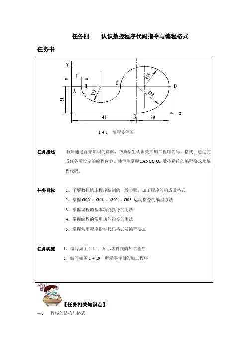
任务四认识数控程序代码指令与编程格式任务书1-4-1 编程零件图任务描述教师通过背景知识的讲解,帮助学生认识数控加工程序代码、格式;通过完成任务所设定的编程内容,使学生掌握FANUC Oi 数控系统的编程格式及编程代码。
任务目标1、了解数控铣床程序编制的一般步骤,加工程序的构成及格式2、掌握G00 、G01 、G02 、G03 运动指令的编程方法3、掌握编程的基本功能指令的用法4、掌握编程的常用功能指令的用法5、掌握常用程序指令代码格式及编程要点任务实施1、编写如图1-4-1 所示零件图的加工程序2、编写如图1-4-19 所示零件图的加工程序【任务相关知识点】一、程序的结构与格式加工程序是数控加工中的核心组成部分,不同的数控系统,其加工程序的结构及程序段格式也可能有某些差异,以FANUC Oi数控系统为例来说明。
1、程序的结构一个完整的程序由程序号、程序内容和程序结束三部分组成,程序的开始部分通常取文件名以“O”+ 四位数字组成、中间是程序段、结束部分用“M30”表示,如图1-4-2所示图1-4-2 程序结构格式(1)程序号程序号是程序的开始部分,为了区别存储器的程序,每个程序都要进行编号,FANUC 系统一般采用英文字母“O”+ 四位数字组成。
(2)程序内容程序内容部分是整个程序的核心,它由许多程序段组成,每个程序由一个或多个指令构成,它表示数控机床要完成的操作。
程序的构成-----由若干个“程序段”组成程序段构成-----每个程序段由按照一定顺序和规定排列的“指令字”组成指令字构成------由表示地址的英文字母、特殊文字和数字集合而成(3)程序结束用程序结束指令M02或M03来结束整个程序2、程序格式:程序的开始部分、程序内容部分和程序结束图1-4-3 程序格式3、程序段组成:由指令字组成图1-4-4 程序结构格式4、指令字由地址符(指令字符)和带符号(由定义尺寸的字)或不带符号(如准备功能字G 代码)的数字数据组成。

MasterCAM四轴编程实例一、任务描述:
二、图纸解读:
该零件右端已在车床加工完成,在加工中心主要加工面、内腔、凸台。
难点是怎样在一次装夹完成加工的程序编写。
三、刀具选择:
刀具一览表
四、工艺路线:
五、编程与加工:
MasterCAM9.1编程:
(1)打开MasterCAM软件,导入装配体XT文件,按F9显示坐标系,平移装配体把编程坐标
原点设置在零件左端面中心。
(2)点击作别图层,设置如下图层:
(3)开毛坯图层,其余关闭,另存STL格式毛坯文件。
(4)将构图面与刀具面设一致。
(5) 开零件图层和使用铣面图层绘制直线,铣平面。
参数设好单击确定出现刀具路径:
实体切削验证:
(6)旋转路径:
右键单机操作管理刀具路径1,选择路径转换弹出菜单:
参数设好后,单击确定,在操作管理菜单生成了新操作:
对不同深度的铣削面参数修改,修改完成后单击操作管理菜单中的重新计算:
实体验证:
(7)铣内腔,开零件图层,使用挖槽图层,选择挖槽加工:
生成的刀具路径:
对刀具路径进行旋转:
实体切削验证:
(8)铣凸台,开零件图层,使用铣凸台图层,选择外轮廓铣削:
对刀具路径进行旋转(同上):
实体切削验证:
(9)后处理
单击操作管理菜单中的执行后处理,储存NC程序:
11。
Mastercam加工中心编程实例介绍Mastercam是一款广泛应用于数控机床编程的软件,通过使用Mastercam可以进行各种复杂的零件加工编程。
本文将通过一个具体的实例来演示如何使用Mastercam 进行加工中心编程。
实例背景假设我们需要对一个铝合金材料进行加工,制作一个带有孔和凹槽的零件。
该零件尺寸为100mm x 100mm x 20mm,图纸如下:加工准备在开始编程之前,我们需要完成以下准备工作:1.确定刀具和夹具的选择:根据零件的形状和要求,选择合适的刀具和夹具。
2.确定机床坐标系:确定机床坐标系原点和方向。
3.导入CAD图纸:将零件图纸导入Mastercam中。
创建新项目1.打开Mastercam软件,并选择“新建项目”。
2.在项目设置中,设置机床类型为“加工中心”。
3.设置刀具库、夹具库等相关参数。
创建加工操作1.在Mastercam中打开导入的CAD图纸。
2.使用绘图工具创建孔和凹槽的几何形状。
3.使用刀具工具栏中的工具选择合适的刀具。
4.根据刀具和加工要求,设置切削参数,如进给速度、切削深度等。
加工路径生成1.在Mastercam中选择“加工路径生成”功能。
2.选择合适的加工策略,如钻孔、铣削等。
3.根据零件形状和加工要求,设置加工路径生成参数,如过渡方式、切割方式等。
仿真和后处理1.在Mastercam中进行仿真操作,检查加工路径是否正确。
2.如果需要输出数控机床程序文件,则选择“后处理”功能,并设置相应的后处理参数。
3.保存并导出数控机床程序文件。
加工操作1.将导出的数控机床程序文件拷贝到数控机床控制系统中。
2.在数控机床控制系统中加载并运行该程序文件。
3.监视加工过程,确保零件按照预期进行加工。
结束语通过本实例,我们演示了如何使用Mastercam进行加工中心编程。
从准备材料到最终完成零件的加工过程都需要仔细规划和操作。
希望本文能为您提供一些参考和帮助,使您能够更好地使用Mastercam进行加工中心编程。
第一节Master CAM的车削编程在本节中将通过图9-5所示零件介绍Master CAM的车端面、粗车、精车、切槽、螺纹切削、钻孔和截断车削过程。
图9-5一、生成端面加工刀具路径(一)设置工件。
1.Main Menu→Toolpaths→Job setup系统弹出如图9-6所示对话框。
图9-6(1)通过Tool Offsets设置刀具偏移。
(2)通过Feed Calculation设置工件材料。
(3)通过Toopath Configuration设置刀具路径参数。
(4)通过Post Processor设置后置处理程序。
2.选择Boundaries设置工件毛坯。
见图9-7对话框。
图9-7(1)通过Stock项目设置工件毛坯大小。
选择Parameters→Take from 2 point设置毛坯的左下角点为(-100,-310),右上角点为(100,10),生成虚线如图9-8所示的毛坯。
(2)通过Tailstock尾座顶尖的参数。
(3)通过Chuck设置卡盘的参数。
(4)通过Steady rest设置辅助支撑的参数。
图9-8(5)选择Ok,工件设置完成。
(二)生成车端面刀具路径1.Main Menu→Toolpaths→Face系统弹出如图9-9所示的对话框。
2.在Tool parameters参数对话框中选择刀具,并设置其他参数。
3.选择对话框中的Face parameters标签,并设置参数。
见图9-10所示。
Face parameters 选项中各参数的含义如下:(1)Entry amountEntry amount输入框用于输入刀具开始进刀时距工件表面的距离(2)Roughstepover当选中Roughstepover输入框前面的复选框时,按该输入框设置的进刀量生成端面车削粗车刀具路径。
(3)Finish stepover当选中Fini9hstepover输入框前面的复选框时,按该输入框设置的进刀量生成端面车削精车刀具路径。