车架有限元分析外文文献翻译
- 格式:doc
- 大小:605.50 KB
- 文档页数:11
基于HyperMesh的运输车车架有限元分析论文基于HyperMesh的运输车车架有限元分析论文0 引言车架作为车辆重要的承载部分,运输车中多数零部件如:驾驶室,发动机,变速箱,车桥等通常都直接与车架相连接。
在运动过程中,车架还承受各零部件产生的各种力与力矩的影响,承载情况的复杂性要求车架必须有足够的刚度和强度来避免其主体发生变形或者断裂的现象,以保证其安全可靠性及使用寿命。
但是,在以往的设计过程中,设计人员大多采用经验公式进行计算,这种方法并不能精准的计算出车架各部件应力和形变。
本文采用HyperWorks软件对车架结构进行有限元分析,运用Radioss及OptiStuct求解器分析了车架的应力和位移形变分布状态及自由模态分析,利用分析结果验证该车架设计的合理性,对后续的结构优化提供理论依据。
1 车架的几何模型及有限元模型本文以某造船厂运输车车架为研究对象,该车架由型钢焊接而成,两根纵梁为矩形截面型钢,总长9440mm,大梁式,前后等宽,纵梁最大断面尺寸为360mm×140mm×20mm,横梁最大断面尺寸为300mm×140mm×20mm,前后端横梁为Π型槽钢,中间横梁为矩形截面型钢,横梁的长度为920mm。
实际中,车架的形状结构复杂,支撑装置和固定装置多种多样,除几何形体不规则外还存在许多倒圆角和圆孔,如果在建模的过程中将这些细微之处全部考虑在内,就会导致网格的密度很大,单元尺寸极小,节点方程的数量庞大,因而增加求解时间,同时局部的网格质量无法保证,容易导致求解失真。
因此,有必要对车架的结构进行合理的简化,建立合理有效的模型,从而减少分析过程中的计算量,提高计算效率。
运用Pro/E三维建模软件对简化处理后的车架结构进行实体建模,为了避免部分零件出现几何缺陷或数据丢失的情况,我们通常将Pro/E 中建立的模型保存为.iges格式文件,把该格式文件直接导入HyperMesh中进行后续的网格划分。
1 前言在汽车三大总成之中,汽车车身代表着汽车开发的水平,在汽车开发中占有主体地位。
由于在车辆行驶过程中,车身结构会在各种振源的激励下产生振动,若这些振源的激励频率接近了车身整体或局部的固有频率,便会发生共振现象,产生剧烈振动和噪声,甚至造成结构破坏。
因此,为了提高汽车的安全性、稳定性和舒适性,就必须对车身结构的固有频率进行分析,并可以通过对其结构的设计来避开各种振源的激励。
文中就是采用有限元分析的方法,对某车型的车身地板进行模态分析,分析其固有频率及振型,为实际生产提供参考依据。
2 车身地板有限元模型的建立车身地板是典型的凹凸槽板结构,而对其的模拟建模有两种方法,一是按凹凸槽的真实形状建模;二是按照文献中提到的方法,即用在凹凸槽处加加强梁的平板结构来模拟,使加强梁的截面参数与实际结构相一致,文中原始模型采用第一种方法。
2.1建模2.1.1平面问题及薄板弯曲车身地板的CAD模型是在Catia软件里创建完成的。
车身的大部分零件是薄板冲压件,板材的厚度h远小于其平面尺寸。
薄板的变形与载荷的作用方式有关,当载荷平行于中面(平分薄板厚度的平面)且沿厚度方向不变,可认为是平面应力问题;若载荷垂直于中面,则将引起薄板的弯曲变形。
以薄板的中面为x-y平面,垂直于中面的轴为z轴。
在平面应力问题中只有平行于x-y平面的三个应力分量:σσττ=,,x y xy yz这三个分量沿厚度h不变,它们只是x和y的函数,与坐标z无关,而其余分量为零。
平面应力的物理方程为:薄板弯曲变形后,中面由平面变成曲面,称为弹性曲面。
中面内各点在垂直于中面的方向的位移w称为挠度。
当w远小于厚度t时,即满足时,可以认为中面无线应变也无角应变,此时称为薄板弯曲的小挠度问题。
若挠度w接近厚度t的量级,就不能再认为弹性曲面内纤维的长度不变,问题将变为非线性的,这种情况称为薄板弯曲的大挠度问题。
工程中的大部分问题是将薄板的弯曲视为小挠度问题,这样可使问题大大简化。
到CAE方法它将节省大量的测试成本,及时指导车身的设计结构,提出优化方法; 有限元法已经成为在车身特性设计和分析过程中不可或缺的[3]。
在结构优化过程中,首先,敏感性分析应该是对的以设计变量的灵敏度来确定目标[4]然后根据灵敏度修改设计变量以获得最佳设计目标与约束条件。
设计变量的灵敏度与A轻量级优化方法相关其目标函数是由客观因素的变化来衡量的单位设计变量的变化,灵敏度分析是opti的基础可以根据敏感度进行结构分析,优化结构分析,这将节省大量的计算时间并改进优化因此,在工业中期望提供一种改进的轻型汽车车身结构,特别是车身框架,其保持所需的强度,刚度和稳定性特性,以满足乘客安全和车辆性能标准。
此外,身体结构应当可使用现有技术和材料制造,以实现减轻重量而不增加成本。
此外,主体结构应该能够减少总成分,以进一步降低成本和制造时间。
2灵敏度分析的基本理论从结构分析可以分为动态分析和静态分析两个方面,结构敏感性分析也可以分为动力敏感性分析和静态敏感性分析。
动态灵敏度分析包括特征值灵敏度分析,传递函数灵敏度分析和动态响应敏感性分析。
静态敏感性分析可以是压力,位移等。
对于车辆,灵敏度分析是指车身刚度强度,自由模式和敏感性分析的应变能,部分结构参数包括材料厚度和横截面转动惯量[5 |。
有两种计算灵敏度的方法,推导方法和伴随结构的方法。
直接推导法,是亲由胡力构成R.Kapoor M.P,然后由许多人开发和推广人们在广泛的领域。
直接推导法具有明显的物理意义概念,简单的数学理论方便计算可扩展从一阶敏感度到高阶灵敏度,因此是广泛的在工业领域[6]。
3 BIW扭转刚度分析汽车BIW的有限元模型由769 862组成元素包括三角形元素和四边形元素重量为371.2公斤。
为了比较车辆扭转刚度试验过程中的有限元分析模型需要使用直径为50 mm的梁单元进行模拟测试设备如图有限元边界条件分析模型如图1所示。
3,左右后方的震动塔都很硬点被限制在X,翻译DOF左右前方震动吸收塔受限于X方向DOF。
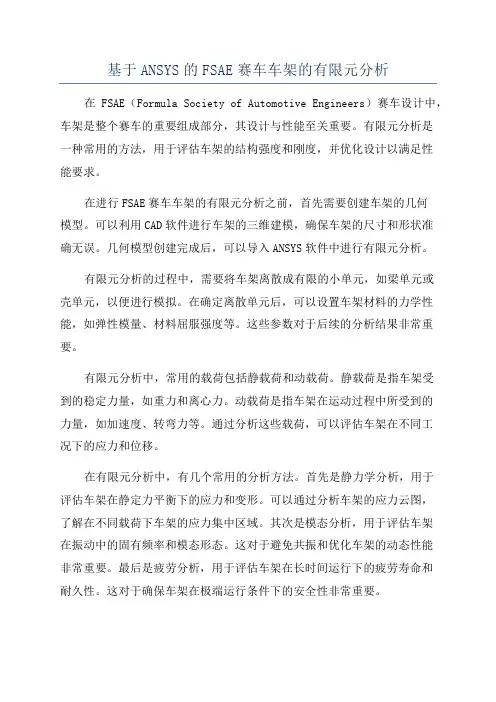
基于ANSYS的FSAE赛车车架的有限元分析在FSAE(Formula Society of Automotive Engineers)赛车设计中,车架是整个赛车的重要组成部分,其设计与性能至关重要。
有限元分析是一种常用的方法,用于评估车架的结构强度和刚度,并优化设计以满足性能要求。
在进行FSAE赛车车架的有限元分析之前,首先需要创建车架的几何模型。
可以利用CAD软件进行车架的三维建模,确保车架的尺寸和形状准确无误。
几何模型创建完成后,可以导入ANSYS软件中进行有限元分析。
有限元分析的过程中,需要将车架离散成有限的小单元,如梁单元或壳单元,以便进行模拟。
在确定离散单元后,可以设置车架材料的力学性能,如弹性模量、材料屈服强度等。
这些参数对于后续的分析结果非常重要。
有限元分析中,常用的载荷包括静载荷和动载荷。
静载荷是指车架受到的稳定力量,如重力和离心力。
动载荷是指车架在运动过程中所受到的力量,如加速度、转弯力等。
通过分析这些载荷,可以评估车架在不同工况下的应力和位移。
在有限元分析中,有几个常用的分析方法。
首先是静力学分析,用于评估车架在静定力平衡下的应力和变形。
可以通过分析车架的应力云图,了解在不同载荷下车架的应力集中区域。
其次是模态分析,用于评估车架在振动中的固有频率和模态形态。
这对于避免共振和优化车架的动态性能非常重要。
最后是疲劳分析,用于评估车架在长时间运行下的疲劳寿命和耐久性。
这对于确保车架在极端运行条件下的安全性非常重要。
通过有限元分析,可以得到车架的应力、位移、变形等结果。
根据这些结果,可以对车架进行优化设计,以提高其结构强度和刚度。
优化设计的方法包括增加材料的厚度和强度,改变车架的结构形式等。
此外,还可以通过有限元分析,评估不同配置和材料对车架性能的影响,以选择最佳的设计方案。
总之,基于ANSYS的有限元分析是FSAE赛车车架设计的重要工具。
通过分析车架的结构强度和刚度,可以优化设计,提高赛车的性能。
南京林业大学本科毕业设计(论文)外文资料翻译翻译资料名称(外文)Stress analysis of heavy duty truck chassis as apreliminary data for its fatigue life predictionusing FEM翻译资料名称(中文)利用重型载货汽车的有限元应力分析的初步数据预测其疲劳寿命院(系):汽车与交通工程学院专业:机械制造及其自动化(汽车设计方向)姓名:学号:指导教师:完成日期: 2012/5/31利用重型载货汽车的有限元应力分析的初步数据预测其疲劳寿命Roslan Abd Rahman, Mohd Nasir Tamin, Ojo Kurdi马来西亚工程大学机械工程系81310 UTM, Skudai,Johor Bahru摘要本文对一重型货车底盘做了应力分析。
应力分析能够确定零件的最大受力点,是分析零部件疲劳研究和寿命预测的重要手段。
前人已有用商用有限元软件ABAQUS软件对底盘模型进行分析的。
本次研究的底盘长12.35米,宽2.45米,材料是ASTM低合金钢710(3级),屈服极限552MPa,抗拉强度620MPa。
分析结果显示,最大应力点出现在底盘与螺栓连接的空缺处,最大应力为386.9MPa,底盘的疲劳破坏将会从最大应力点开始向车架各部位蔓延。
关键字:应力分析,疲劳寿命预测,货车底盘1.0简介在马来西亚,很多货车的车架寿命都有20多年,20多年架就会有使用安全的问题。
因此,为了确保底盘在工作期间的安全性能,就有必要对底盘作疲劳研究和寿命预测。
利用有限元法作应力分析能够确定受最大应力的关键点,这个关键点是导致底盘疲劳损伤的因素之一。
应力的大小能够预测底盘的寿命,所以可以根据应力分析的结果精确地预测底盘的寿命,应力分析越精确,底盘寿命预测的越合理。
本文是用商用有限元软件ABAQUS 软件完成底盘应力分析的。
汽车工业(汽车总成及各部件)在马来西亚的工业中占据非常重要的地位。
中英文文献翻译—汽车车架的结构The frame is the basic XXX components。
If the frame is too flexible。
it XXX and control。
On the other hand。
if the frame is too rigid。
it can cause unnecessary ns that can be felt by the driver and passengers。
Thus。
the design of the car's frame and XXX the car's noise level。
n strength。
XXX.Car manufacturers use several different frame structures in their n。
One of the most commonly used structures is the shell and girders of n structure。
which has been used since the 1970s。
This structure provides a balance een XXX。
allowing for XXX driving.However。
it is important to note that the frame structure isjust one aspect of a car's overall design。
Other factors。
such asthe engine。
n。
and aerodynamics。
XXX。
car manufacturers must carefully consider all aspects of a car's design to create ahigh-quality and XXX.At present。
附录1:外文翻译CAE的技术种类有很多,其中包括有限元法,边界元法,有限差法等。
每一种方法各有其应用的领域,而其中有限元法应用的领域越来越广,现已应用于结构力学、结构动力学、热力学、流体力学、电路学、电磁学等。
ANSYS软件是融结构、流体、电场、磁场、声场分析于一体的大型通用有限元分析软件。
由世界上最大的有限元分析软件公司之一的美国ANSYS开发,它能与多数CAD软件接口,实现数据的共享和交换,如Pro/Engineer, NASTRAN, Alogor, I-DEAS, AutoCAD等,是现代产品设计中的高级CAE工具之一。
ANSYS有限元软件包是一个多用途的有限元法计算机设计程序,可以用来求解结构、流体、电力、电磁场及碰撞等问题。
因此它可应用于以下工业领域:航空航天、汽车工业、生物医学、桥梁、建筑、电子产品、重型机械、微机电系统、运动器械等。
有限元分析(FEA,Finite Element Analysis)的基本概念是用较简单的问题代替复杂问题后再求解。
它将求解域看成是由许多称为有限元的小的互连子域组成,对每一单元假定一个合适的(较简单的)近似解,然后推导求解这个域总的满足条件(如结构的平衡条件),从而得到问题的解。
这个解不是准确解,而是近似解,因为实际问题被较简单的问题所代替。
由于大多数实际问题难以得到准确解,而有限元不仅计算精度高,而且能适应各种复杂形状,因而成为行之有效的工程分析手段。
有限元是那些集合在一起能够表示实际连续域的离散单元。
有限元的概念早在几个世纪前就已产生并得到了应用,例如用多边形(有限个直线单元)逼近圆来求得圆的周长,但作为一种方法而被提出,则是最近的事。
有限元法最初被称为矩阵近似方法,应用于航空器的结构强度计算,并由于其方便性、实用性和有效性而引起从事力学研究的科学家的浓厚兴趣。
经过短短数十年的努力,随着计算机技术的快速发展和普及,有限元方法迅速从结构工程强度分析计算扩展到几乎所有的科学技术领域,成为一种丰富多彩、应用广泛并且实用高效的数值分析方法。
有限元分析报告报告材料英文文献The Basics of FEA Procedure有限元分析程序的基本知识2.1 IntroductionThis chapter discusses the spring element, especially for the purpose of introducing various concepts involved in use of the FEA technique.本章讨论了弹簧元件,特别是用于引入使用的有限元分析技术的各种概念的目的A spring element is not very useful in the analysis of real engineering structures; however, it represents a structure in an ideal form for an FEA analysis. Spring element doesn’t require discretization (division into smaller elements) and follows the basic equation F = ku.在分析实际工程结构时弹簧元件不是很有用的;然而,它代表了一个有限元分析结构在一个理想的形式分析。
弹簧元件不需要离散化(分裂成更小的元素)只遵循的基本方程F = ku We will use it solely for the purpose of developing an understanding of FEA concepts and procedure.我们将使用它的目的仅仅是为了对开发有限元分析的概念和过程的理解。
2.2 Overview概述Finite Element Analysis (FEA), also known as finite element method (FEM) is based on the concept that a structure can be simulated by the mechanicalbehavior of a spring in which the applied force is proportional to the displacement of the spring and the relationship F = ku is satisfied.有限元分析(FEA),也称为有限元法(FEM),是基于一个结构可以由一个弹簧的力学行为模拟的应用力弹簧的位移成正比,F = ku切合的关系。
The Basics of FEA Procedure有限元分析程序的基本知识2.1 IntroductionThis chapter discusses the spring element, especially for the purpose of introducing various concepts involved in use of the FEA technique.本章讨论了弹簧元件,特别是用于引入使用的有限元分析技术的各种概念的目的A spring element is not very useful in the analysis of real engineering structures; however, it represents a structure in an ideal form for an FEA analysis. Spring element doesn’t require discretization (division into smaller elements) and follows the basic equation F = ku.在分析实际工程结构时弹簧元件不是很有用的;然而,它代表了一个有限元分析结构在一个理想的形式分析。
弹簧元件不需要离散化(分裂成更小的元素)只遵循的基本方程F = ku We will use it solely for the purpose of developing an understanding of FEA concepts and procedure.我们将使用它的目的仅仅是为了对开发有限元分析的概念和过程的理解。
2.2 Overview概述Finite Element Analysis (FEA), also known as finite element method (FEM) is based on the concept that a structure can be simulated by the mechanical behavior of a spring in which the applied force is proportional to the displacement of the spring and the relationship F = ku is satisfied.有限元分析(FEA),也称为有限元法(FEM),是基于一个结构可以由一个弹簧的力学行为模拟的应用力弹簧的位移成正比,F = ku切合的关系。
汽车底盘车架设计中的有限元分析技术应用对于汽车制造商和设计师来说,设计一款坚固、耐用且安全的底盘车架是至关重要的。
在现代汽车设计过程中,有限元分析技术(Finite Element Analysis, FEA)被广泛应用于底盘车架设计中,以保证其结构的可靠性和性能。
本文将探讨有限元分析技术在汽车底盘车架设计中的应用,并介绍其在结构优化、材料选择和碰撞安全等方面的重要作用。
有限元分析技术是一种计算求解结构力学问题的数值分析方法,通过将底盘车架分割成有限个小单元(有限元),借助计算机进行离散化求解,从而得到车架在外力作用下的应力、应变、位移等力学响应。
这一计算模型可以准确描述车架的力学特性,并预测其结构行为。
首先,有限元分析技术在汽车底盘车架设计中的应用之一是结构优化。
通过对车架的有限元模型进行各种负载条件和约束条件的分析,设计师可以确定哪些局部区域受到最大的应力,从而确定哪些地方需要加强或重新设计。
例如,在汽车底盘车架的连接点和受力集中的区域,可以使用有限元分析来评估应力分布情况,以确保其强度和刚度满足设计要求。
此外,有限元分析还可以帮助设计师优化车架的减重设计,在保证结构安全性和刚度的前提下最大限度地降低车重,提高燃油经济性。
其次,有限元分析技术在材料选择方面也发挥着重要作用。
通过在有限元模型中引入不同材料的特性参数,设计师可以比较不同材料组合的效果,选取最佳材料以满足设计要求。
例如,比较不同材料的强度、刚度、耐腐蚀性等特性,以在保证结构安全性的前提下选择最轻最强的材料。
这种材料选择的优化可以有效地提高整个车架的性能,并且在节约成本的同时提高车辆的可靠性和可维护性。
最后,有限元分析技术在碰撞安全方面也具有重要意义。
通过对车架在碰撞事故时的有限元分析,设计师可以模拟和预测车辆受到冲击后的结构变形、应力分布和吸能能力等。
这对于汽车碰撞安全的设计和评估非常重要。
通过有限元分析的结果,设计师可以根据不同碰撞力的作用方式,合理设计车架吸能结构,以保护车辆内部乘客的安全。
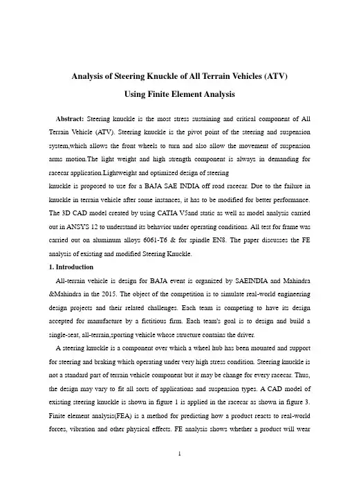
Analysis of Steering Knuckle of All Terrain Vehicles (ATV)Using Finite Element AnalysisAbstract: Steering knuckle is the most stress sustaining and critical component of All Terrain Vehicle (ATV). Steering knuckle is the pivot point of the steering and suspension system,which allows the front wheels to turn and also allow the movement of suspension arms motion.The light weight and high strength component is always in demanding for racecar application.Lightweight and optimized design of steeringknuckle is proposed to use for a BAJA SAE INDIA off road racecar. Due to the failure in knuckle in terrain vehicle after some instances, it has to be modified for better performance. The 3D CAD model created by using CATIA V5and static as well as model analysis carried out in ANSYS 12 to understand its behavior under operating conditions. All test for frame was carried out on aluminum alloys 6061-T6 & for spindle EN8. The paper discusses the FE analysis of existing and modified Steering Knuckle.1. IntroductionAll-terrain vehicle is design for BAJA event is organized by SAEINDIA and Mahindra &Mahindra in the 2015. The object of the competition is to simulate real-world engineering design projects and their related challenges. Each team is competing to have its design accepted for manufacture by a fictitious firm. Each team's goal is to design and build a single-seat, all-terrain,sporting vehicle whose structure contains the driver.A steering knuckle is a component over which a wheel hub has been mounted and support for steering and braking which operating under very high stress condition. Steering knuckle is not a standard part of terrain vehicle component but it may be change for every racecar. Thus, the design may vary to fit all sorts of applications and suspension types. A CAD model of existing steering knuckle is shown in figure 1 is applied in the racecar as shown in figure 3. Finite element analysis(FEA) is a method for predicting how a product reacts to real-world forces, vibration and other physical effects. FE analysis shows whether a product will wearout, break, or work the way it designed.The advanced optimization techniques help to explore the light weight architecture. Rajendran et al discusses the process of designing light weight Knuckle from scratch which can be applicable for many casting components. To derive the optimal load path required for the major load cases a topology optimization is performed on the design volume and prepare a concept model from the topology results generated. The model is verified for all the required extreme loads & the durability load which helps for significant mass reduction from model. Chang and Tang presented an integrated design and manufacturing approach that supports shape optimization of structural component. The approach starts from a primitive concept stage, where boundary and loading condition of structural component are given to the designer. Topology optimization is conducted for a structural layout. A 3D tracked vehicle roadarm is employed to illustrate overall design process and various techniques involved. According to B.Babu et al, Steering Knuckle plays major role in many direction control of the vehicle it is also linked with other linkages and supports the vertical weight of the car. Study involves modelling of the steering knuckle with the design parameters using the latest modelling software, and also it includes the determination of loads acting on the steering knuckle as a function of time. This is done for finding out the minimum stress area.Chang Yong Song discusses reliability-based design optimization (RBDO) of an automotive knuckle component under bump and brake loading conditions. The probabilistic design problem is to minimize the weight of a knuckle component subject to stresses, deformations, and frequency constraints in order to meet the given target reliability. The initial design is generated based on an actual vehicle specification. The finite element analysis is conducted using ABAQUS, and the probabilistic optimal solutions are obtained via the moving least squares method (MLSM) in the context of approximate optimization.In the present study, design of a durable and reliable steering knuckle for a racecar being an ultimate aim to be achieved. Development of racecar components tied with the regulations drawn by the organizer. In existing design of knuckle, which has very less weight, but at the time of race a steering arm has separated from the knuckle due to low strength of knuckle and high strength of bolted joint as shown in figure 2. While steering an arm pulls knuckletowards a car for turning, so it should be assembled with the knuckle to strengthen a steering and braking mechanism. In proposed design, a single piece of knuckle includes the steering arm and brake caliper and not provide any bolted joint to improve its strength and attached to knuckle directly.Figure 1.CAD model of existing knuckle Figure 2. Existing KNUCKLEFigure 3.SAE INDIA racecar2. Design of Existing KnuckleThe objective of the study is to design a steering Knuckle have minimum weight as well as maximum strength. To satisfy this requirement, aluminium 6061-T6 alloys are the best option for nowadays-automobile industry due to light weight as well as has low density and compatible yield strength. Table 1 shows the physical and mechanical properties of the Aluminium 6061 alloy.Considering above facts, a CAD model of the steering Knuckle was prepared using CATIA V5 as shown in Figure 1. The model was designed, consideringgeneral suspension geometry parameters of an off-road vehicle. The existing knuckle is a Hub type is as shown in figure 2. In which the wheel hub fitted in bearing and tyre mounted on wheel hub. In this type of knuckle the mounting of brake calliper and steering arm is directly attached without an external joint but, to reduce the cost of manufacturing as well as required raw material, design of knuckle includes force exerted by three parts.i. Frameii. Steering armiii. Brake Calliper mountingLoads consider as per weight biasing and resolve in three component x, y and z direction. G's consideration for force calculation in x, y, and z direction is 6.6, 4.6 and 2.3 respectively.3. Structure and Design of Modified KnuckleThe aim of design is produce reliable and durable steering knuckle for a racecar to overcome the previous year’s failure. Proposed design of knuckle is spindle type, in which, the frame and spindle is is made up of same or different material. The material is used to design a frame of vehicle is AL6061-T6 whose properties are given in table 1. To restrict the lateral movement of wheel hub, lock nut arrangement is provided on end of spindle and to increase the strength of bolted joint, spindle is made-up of material EN8. The design process was started with preliminary study on the existing steering knuckle constituent used for the previous racecar including investigating the existing knuckle design.The design also needs to follow the criteria and regulations drawn by BAJA organizer, mainly depends on suspension as well as steering geometry. In general, a steering knuckle has three connections on the body part connecting to the upper arm, lower arm and tie rod. Therefore, the design needs to stress on these three connections, as well as one side of connectors where brake caliper attached. Then final design evaluated through FEA simulation in order to estimate the deflections,stress distribution as well as the weight. According to the result the optimized the design by thickness of material or applying fillet and chamfer on corners. The proposed design is shown in figure 4.Figure 4.Modified Knuckle Design (Frame) Figure 5.Modified Knuckle Design (Spindle)Figure 6.Modified Knuckle Design (Spindle)3.1 Material SelectionVarious types of materials are currently used for the steering knuckle component like grey cast iron, white cast iron. These materials have high yield strength but the weight of the material is more which is the limitation of racecar. Hence searching for the alternate material with nearest yield strength and light in weight, for this factor and cost consideration the Aluminium alloy 6061-T6 is used.Table 1.Material Input Data for Al 6061-T6 and EN-83.2 Load DistributionCurb weight of vehicle considered = 2500NWeight of One person As per SAE rule = 1110 NGross Weight of Vehicle = 3610 NFor analysis consider when vehicle is jump and landing on single front wheel so, total weight of vehicle comes on spindleI. Load on spindle = 3561 NII. Braking Force = 3500 NIII. Braking Torque = 331.5 N-mIV. Force On Steering Arm = 600 N4. Finite Element AnalysisFor the FEA of existing and modified Knuckle, 3D model is created in CATIA v5 and save in IGS format and imported in ANSYS 12.0. The material properties as shown in table 1 have been assign in engineering data. Model is mesh with Solid 187 hexahedral 10-node element. The solid elements has three degree of freedom i.e. translation in X, Y and Z direction. The finite element analysis of knuckle has been carried out for different boundary condition and observed the stress level as per material property of material. All the results carried out using ANSYS 12.0 are shown in tabulated format.4.1. On Existing DesignAn existing design is hub type steering knuckle, to observe that maximum stress produce into steering knuckle, model subjected to extreme conditions. Steering knuckle was constraint at upper and lower ball joint mountings. As per loading conditions, the weight biasing on front side on each wheel 60kg weight considered. According to speed of vehicle, three component of force was considered on x,y, z direction. Apply load of1400 N, 2800 N and 4000 N on X, Y and Z direction respectively, as shown in figure 7. A mesh model of existing knuckle is shown in figure 8 having 181775 Nodes and 120120 elements. Referring to the analysis results, the maximum stress on designs are less than material yield strength and very less deflection under the assigned loads. In addition, mass of the models are also evaluated in the CATIA software since the ultimate aim of the current project is to design a lightweightsteering knuckle.Figure 7. Boundary Conditions Figure 8. Mesh model of Existing knuckleFigure 9.Equivalent Stress Figure 10. Maximum Principle Stresses 4.2. On Modified DesignThe modified design of knuckle is spindle type. In this type, wheel hub rotated on spindle and spindle fitted in frame by interference fit. For reducing material and according to loading condition,the modified knuckle is designed in two parts.I. Frame II. Spindle4.2.1. FrameThe frame is a structure in which the upper and lower suspension arm pivoted and it consists of mounting for steering arm and brake calliper. For FE analysis, the boundary conditions apply as discuss in load distribution section and as shown in Figure. 11 and mesh model is shown in figure 12 having 196446 nodes and 127590 element. By observing result, it is found that it has very less deformation as 0.14115 mm.Figure 11.Boundary conditions for Frame Figure 12.Mesh model of modified knuckleFigure 13.Equivalent von-meshes stress Figure 14. Maximum principle stresses4.2.2. SpindleThe wheel hub rotated around the spindle, hence vertical force acting on spindle because of dynamic weight transfer at the time of landing of car after jump. Therefore, the spindle has capacity of sustain all forces, which experience during dynamic condition. Keep this fact in mind decided to use the EN8 material for spindle. EN 8 is easily available in local market and it is cheaper. The boundary condition for FEA is as shown in figure 15. After meshing of spindle 147630 nodes and 101000 elements are generated.Figure 15.Boundary condition Figure 16. Mesh model of spindleFigure 17.Normal Stresses Figure 18.Equivalent Stresses5. Result & DiscussionFrom the analysis of existing and modified knuckle, it has been observed that the stress is quite changes in the modified design but the location of maximum stress have same. In the existing design the maximum stress is observed where the upper and lower ball joint are pivoted. The existing design has a maximum stress of 72.394MPa is occurred near pivot. Modified design is complete one piece of knuckle steering where holes for bolting is not required as it has separate arrangement. Due to this, for the same boundary condition, the stress location has been changed and it is observed that it maximum at mounting of steering. The complete FEA results for the existing and modified design areas shown in table 2.Table 2. FEA Results Compression for Existing and Modified Knuckle6. ConclusionThe Existing design of knuckle is to be applied for an SAEINDIA BAJA 2015 car was successfully fulfils the load-bearing requirement. The external arrangement for steering arm and Brake calliper is failed in Dynamic condition. The ultimate goal of study is to design and produce the steering knuckle, which capable to bear loads at dynamic condition as well as light Weight. Aluminium 6061-T6 alloy was found to be the best material for the component due to the good physical and mechanical properties as well as lightweight. It was analysedthrough FE analysis that the models of the knuckle are below the stress values and very less deflection under the applied loads. The model to be analysed further taking consideration of the good stress results. Hence for further modification in terrain vehicle for SAEINDIA BAJA 2016 racecar an existing knuckle has to be replaced with modified knuckle to improve its strength to reduce failure of joint.全地形车辆转向节的有限元分析摘要:在全地形车辆中转向节是最易承受压力的关键组件,转向节是转向和悬挂系统的轴心点,它使得前轮能够转向和悬挂部件进行摆臂运动。
基于ANSYS自行车车架静强度有限元分析摘要车架部件是构成自行车的基本结构体,也是自行车的骨架和主体,其他部件也都是直接或间接安装在车架上的。
车架部件同时也是自行车上重要的承载部件,自行车所受到的各种载荷最终都传递给车架,因此,车架结构性能的好坏直接关系到骑乘者的安全和整车设计的成败。
通过有限元法对车架结构进行性能分析,在设计时考虑车架结构的优化,对提高整车的各种性能,降低设计与制造成本,增强市场竞争力等都具有十分重要的意义。
大型通用有限元软件ANSYS凭借其强大的分析功能和高度可靠性,在结构静力分析和优化设计等方面具有无可比拟的优越性。
本文以某自行车车架结构为研究对象,通过对PROE和ANSYS软件的学习、消化与吸收,采用实体单元,对车架结构的有限元建模、车架结构的静态特性分析问题进行了研究。
以车架的静强度校核为研究载体,以车架结构的最优化为目标,以节约材料和减轻重量为最终目的,阐述了应用ANSYS进行结构优化设计的基本指导思想及方法步骤。
通过对某自行车车架结构的有限元仿真及结构优化,了解了有限元分析的思路和方法,阐述了有限元在自行车结构分析和优化中的重要意义,对车架的设计开发也具有重要的借鉴意义。
关键词:自行车车架;有限元分析;ANSYS;静强度Finite element analysis of the static strength bicycle framebased on ANSYSAbstractFrame constitute the basic components of bicycle structure, but also the skeleton and subject, the bicycle in other parts are directly or indirectly installed in the frame. Chassis parts are also important parts of the bicycle, bicycle was carrying loads were eventually to frame; therefore, the frame structure is directly related to the safety of riding and the success or failure of the whole design. Through the method of finite element analysis frame structure, performance in the design of optimized frame structure, to improve the performance of vehicle design and reduce manufacturing cost, strengthens the market competition has the extremely vital significance. The universal finite element software ANSYS relies on its strong analysis function and high reliability, in static structure analysis and optimization design has incomparable advantage. Based on a bicycle frame structure as the research object, by the learning ,digestion and absorption of ANSYS and PROE software, with solid element, the finite element modeling of frame structure , static characteristic analysis are discussed. In the frame of static intensity for research, based on the frame structure optimization for target, to save material and reduce weight as the final purpose, this expounds ANSYS for structure optimization design method and the basic guiding thought of the steps.Based on a bicycle frame structure finite element simulation and optimization of the structure ,this paper understands the thoughts and methods of the finite element analysis, describes the significance of finite element analysis in bicycle structure analysis and optimization, on frame design and development also has important significance.Keywords: Bicycle frame; Finite element; ANSYS; Static strength目录第一章绪论...............................................................................................................................- 1 -1.1研究背景与意义 (1)1.2研究的内容和方法 (2)1.3本章小结 (3)第二章自行车车架有限元分析模型的建立...........................................................................- 4 -2.1三维实体模型的建立 (4)2.1.1 PROE简介.............................................................................................................- 4 -2.1.2 车架三维模型分析.................................................................................................- 5 -2.1.3 车架三维实体模型的建立与修改............................................................................- 5 -2.2有限元分析理论简介 (6)2.2.1 有限元的基本概念和原理 ......................................................................................- 6 -2.2.2 有限元方法的特点.................................................................................................- 7 -2.3ANSYS软件介绍 (8)2.3.1 ANSYS在有限元软件中的地位............................................................................- 8 -2.3.2 ANSYS的发展和特点..........................................................................................- 8 -2.3.3 ANSYS的分析步骤 .............................................................................................- 9 -2.4车架有限元模型的建立 (10)2.4.1 PROE和ANSYS接口的连接.............................................................................- 10 -2.4.2 单元类型的选择 ..................................................................................................- 15 -2.4.3 定义材料属性......................................................................................................- 15 -2.4.4划分网格..............................................................................................................- 16 -2.5有限元模型建立的步骤 (16)2.6本章小结 (21)第三章车架的加载和求解.....................................................................................................- 22 -3.1设定位移边界条件 (22)3.2设定载荷 (23)3.3求解 (24)3.4本章小结 (25)第四章车架有限元结果分析.................................................................................................- 26 -4.1查看分析结果 (26)4.2结果的分析 (28)4.3不同约束条件的对比 (29)4.4本章小结 (32)第五章全文总结.....................................................................................................................- 33 -致谢...........................................................................................................................................- 34 -参考文献:...............................................................................................................................- 35 -附录1:英文文献....................................................................................................................- 36 -附录2: 中文文献 ....................................................................................................................- 43 -第一章绪论第一章绪论1.1 研究背景与意义众所周知,我国是世界上自行车生产量和持有量最多的国家,是名副其实的自行车王国。
附录附录AAn Analysis of Idling Vibration for a Frame StructuredVehicleABSTRACTA finite element model for an entire frame-structured sports utility vehicle was made to evaluate the characteristics of the idling vibrations for the vehicle. The engine exciting forces were determined by Souma's method to simulate the idling vibrations. The modeling of the power plant and the entire vehicle was verified by the reasonable agreement of the experiment and calculation results. Attention was focused on the frequency of the first-order vertical bending mode for the frame. It has become clear that the idling vibration level of the vehicle is lowered by decreasing the frequency of the first-order frame bending mode. INTRODUCTIONOne of the defects of a diesel vehicle, which has fuel and economical efficiency, is idling vibration for a vehicle body. In a diesel engine, sharp pressure rise caused by the generation of the thermal energy affects the pistons. In the crank system, which converts the linear motion into the rotary motion, two types of reaction forces excite the engine block: the reaction caused by the alternation of the velocity vector in each moving parts, and by the non-uniform rotary motion generated by the finite number of cylinders. The forces transmit to an engine block, an engine foot, a rubber engine mount, a frame, a rubber cab-mount, and then a vehicle body, which make occupants uncomfortable.The idling vibration for large-sized commercial vehicles was estimated at the early development stage, and the measures against the vibration were taken by simulating the engine exciting forces with Souma…s method,and entering them to a vehicle model.In this paper, the idling vibration was determined by entering the engine exciting forces to the vehicle model, which was made of the finite element of the frame and the body for a small-sized recreational vehicle (RV). Also in this paper, how the natural modes for the frame changes in the vehicle condition is analyzed, and it was indicated that the natural frequency of the first-order vertical bending for the frame had a significant effect. ANALYSIS OF THE VEHICLE BODY VIBRATIONFigure 1 shows the results of analyzing the frequencies of the acceleration in vertical vibration generated on the seat rail while idling in small-sized RV powered by 4-cylinder diesel engine. The main part of the idling vibration is the second-order engine rotation. The 0.5th, 1st, and 1.5th -orders are also critical. However, these orders are caused by the varied combustion between cylinders. A measure against the varied combustion can be expected by improving the injection system. In this research, only 24Hz of the second-order at the idling rotation speed of 720rpm is focused on as a measure in the vehicle structure. Besides, a measure for lowering the vibration is studied because the vertical vibration on seats has a great damaging effect on human sense.IDENTIFICATION OF THE ENGINE EXCITING FORCEThere are three paths for the engine to excite vibration to a vehicle body: through an engine mount, a driving system, and a tail pipe. In this paper, the path through an engine mount, which has a greatest effect, is studied. The various types of methods to identify the exciting force through an engine mount are known. In this paper, Souma‟s method is used. OUTLINE OF SOUMA’S METHODThe cause of the exciting force to an engine block in the controversial frequency domain of the idling vibration is considered. First, the combustion pressure that acts on the pistons is considered to cause the vibration. However, assuming that a piston crankshaft does not move with a flywheel and an engine block fixed in some way, the engine components are supposed to be completely rigid in this frequency domain. In this situation, the engine block will not vibrate if the piston crankshaft does not move in spite of the rapid pressure rise in a combustion chamber due to the diesel combustion.Accordingly, the direct cause of the engine block vibration is not the combustion pressure but the reaction against the piston crankshaft movement. To determine the exciting force to the engine block, the reaction forces against the movement of the mass (mainly in crank system and piston system), which works inside and outside of the engine block, may be calculated.In So uma‟s method, the non-uniform rotary motion in the crank system is found by measuring the pulse generated in a ring gear of the flywheel. Then, the vertical motion in the connected piston system is calculated to determine the exciting force to the engine block using each mass specification value.VERIFICATION OF THE ACCURACY IN THE EXCITING FORCEThe exciting forces are added at the point corresponding to the crankshaft on the entire vehicle model (described later). The vibration on the head cover and the right engine foot, which the exciting forces mostly affect, is estimated. The results of comparing the calculation with the experiment are shown in Figure 2 and 3. In Figure 2 and 3, 5 types of calculated results are shown considering the idling rotation speed changes.In Figure 2 and 3, the calculation and the experiment are identified around 24 Hz, 48 Hz, and 72 Hz of 2nd, 4th, and 6th-orders at the speed of 720 rpm. The data of the left engine foot, which is not shown in this paper, is also almost identified. In this frequency domain, as for the vibration, the engine and the vehicle body are insulated by the engine mount. The body hardly affects the engine vibration. As the data of the experiment and the calculation is identified in this domain, the power plant modeling and the exciting force can be considered reasonable.However, around 12 Hz of 1st-orders, data is not much identified. In this frequency domain, the vibration of the engine and the vehicle body are mutually coupled through the engine mount. Therefore, the accuracy of the vehicle body model has a damaging effect. IMPROVEMENT OF THE MEASURING ACCURACY IN LOW-FREQUENCY VIBRATIONThe engine exciting force was determined using Souma‟s method, and the vibration in each part of the engine was calculated by adding the exciting force. So far, however, the calculated data has not been much identified with the actual measurement. Therefore, the accuracy of the actual measurement is improved. In the surface vibration of the engine, the low-frequency vibration, which causes the idling vibration, and the high-frequency vibration, which causes noise, are mixed. When the mixed vibration is measured with a piezo element acceleration pickup, the high-frequency order is emphasized and the target low-frequency order becomes relatively small. For example, the measured acceleration to time waveform for the vertical vibration in the right engine foot is shown in Figure 4.In this paper, a strain gage acceleration pickup, which measures force acting on the inner weight by strain, is used. This device, which is larger than a piezo element acceleration pickup, is more sensitive to the acceleration. Besides, silicon oil is filled inside to protect the detecting parts in this device, which mechanically blocks off the high-frequency order. The measured acceleration to time waveform for the vertical vibration with the device is shown in Figure 5. Compared with Figure 4, Figure 5 shows only thelow-frequency order although the same area was measured. In this way, the high-frequency order is blocked off, which results in the higher sensitivity with the device. This time, the device, which measures the acceleration ranging from 0 to 20m/s2,was used. This device is easily calibrated using G-forces because it has the higher sensitivity. When a piezo element acceleration pickup was used, the differences between the calculation and the experiment were 20-40% in the main order of the vibration, and a few times in other orders. Therefore, the principle of Souma‟s method using a piez o element accelerationpickup has been in doubt. However, the data of the experiment and the calculation has been identified as shown in Figure 2 and 3 since a strain gage acceleration pickup, which has been used in the experiment of movement performance, was used for an engine.Fig. 1 Seat rail vertical vibration Fig. 2 Head cover lateral vibrationFig. 3 Right engine foot vertical vibration Fig.4 Measurement with piezo element acceleration pickup ENTIRE VEHICLE MODELFigure 6 shows the body model. Interior and exterior equipments such as doors and seat are added in the form of 85 mass points to the main structure modeling detailed with sheet metal finite elements. The grid points are 61,912. Figure 7 shows the model where a frame, a suspension, and an engine are combined, and a fuel tank and a bumper is added in the form of concentrated mass. The grid points are 39,262.Combining the models shown in Figure 6 and 7 using cabmount makes the entire vehicle model. Total grid points mounts to 101,174. The calculation time is 3,293 seconds using IBMSP2, MSC/NASTRAN Version 70.5.2. The calculating method is package calculation. If the model becomes on larger scale, the model must be calculated by the block structure.Figure 8 shows the frequency response function, indicating the responses of the frame with the right back engine mount after exciting the driver‟s seat rail. In the frequency ranging from 20 to 30 Hz, which is required for the analysis, the data of the experiment is qualitatively identified with that of the calculation.Fig. 5 Measurement with strain gage acceleration pickup Fig. 6 Body modeFig.7 Frame,power plant and suspension model Fig.8 Frequency response function CORRELATION ANALYSIS OF THE MODESFrom the viewpoint of vibration characteristics, it can be considered that an entire vehicle is insulated by the engine mount and the cabmount, which have relatively small spring constants, although the insulation is not complete. When the entire vehicle is divided into block structures by each insulating mount and suspension, the body has 4 block structures:(1) Block where interior equipment is added in the form of concentrated mass to the body as shown in Figure 6, which is described as “body”, hereafter.(2) Block where the fuel tank and the bumper are added in the from of concentrated mass to the frame as shown in Figure 7, which is described as “frame,” hereafter.(3) Power plant(4) SuspensionAmong the above block structures, (1) body and (2) frame have the natural frequency around 24 Hz in the idling vibration. The vibration characteristics for the body, the frame and the entire vehicle model are compared and investigated.COMPARISON OF NATURAL FREQUENCYFigure 9 shows the distribution of the natural vibration frequency in each block structure and in the vehicle condition. The frame has 17 natural modes below 50Hz. In Figure 7, the model mounting a power plant and a suspension on the frame, is called Y chassis, which has 35 natural modes below 50 Hz. Y chassis makes the entire vehicle model by mounting the body, which has 94 natural modes below 50 Hz.When the number of natural modes of Y chassis is added to 61 natural modes of the body, total number of the modes amounts to 96. The number of the natural modes of the entire vehicle model (94) is less than the above total number by 2 modes. This is because 2 natural modes became above 50 Hz by combining Y chassis and the body, as the result of analyzing the mode correlation described later.Fig. 9 Natural modes in frequency domain附录B具有车架结构车辆的怠速震动分析摘要建立全车架结构SUV的有限元模型,用来评价车辆的怠速震动特性。
南京林业大学本科毕业设计(论文)外文资料翻译翻译资料名称(外文)Stress analysis of heavy duty truck chassis as apreliminary data for its fatigue life predictionusing FEM翻译资料名称(中文)利用重型载货汽车的有限元应力分析的初步数据预测其疲劳寿命院(系):汽车与交通工程学院专业:机械制造及其自动化(汽车设计方向)姓名:学号:指导教师:完成日期: 2012/5/31利用重型载货汽车的有限元应力分析的初步数据预测其疲劳寿命Roslan Abd Rahman, Mohd Nasir Tamin, Ojo Kurdi马来西亚工程大学机械工程系81310 UTM, Skudai,Johor Bahru摘要本文对一重型货车底盘做了应力分析。
应力分析能够确定零件的最大受力点,是分析零部件疲劳研究和寿命预测的重要手段。
前人已有用商用有限元软件ABAQUS软件对底盘模型进行分析的。
本次研究的底盘长12.35米,宽2.45米,材料是ASTM低合金钢710(3级),屈服极限552MPa,抗拉强度620MPa。
分析结果显示,最大应力点出现在底盘与螺栓连接的空缺处,最大应力为386.9MPa,底盘的疲劳破坏将会从最大应力点开始向车架各部位蔓延。
关键字:应力分析,疲劳寿命预测,货车底盘1.0简介在马来西亚,很多货车的车架寿命都有20多年,20多年架就会有使用安全的问题。
因此,为了确保底盘在工作期间的安全性能,就有必要对底盘作疲劳研究和寿命预测。
利用有限元法作应力分析能够确定受最大应力的关键点,这个关键点是导致底盘疲劳损伤的因素之一。
应力的大小能够预测底盘的寿命,所以可以根据应力分析的结果精确地预测底盘的寿命,应力分析越精确,底盘寿命预测的越合理。
本文是用商用有限元软件ABAQUS 软件完成底盘应力分析的。
汽车工业(汽车总成及各部件)在马来西亚的工业中占据非常重要的地位。
车架有限元分析英文翻译附件9:华南理工大学广州汽车学院本科生毕业设计(论文)翻译英文原文名FINITE ELEMENT ANALYSIS ANDOPTIMIZATION OF A HEA VY TRUCK FRAME 中文译名重型货车汽车车架的有限元分析及优化设计系别汽车系专业班级车辆六班学生姓名马俊指导教师李利平填表日期2012年5月4日二00 年月英文原文版出处:译文成绩:指导教师(导师组)签名:译文:重型货车汽车车架的有限元分析及优化设计摘要本文针对某重型汽车厂载货汽车车架在实际使用过程中出现的破坏等现象,利用美国大型有限元分析软件ANSYS对其进行静、动态分析,找出车架破坏的主要原因,并提出结构改进方案,通过对各方案的分析对比,提出合理的结构改进,对改进后的结构进行优化设计,最后根据优化结果生产样车,进行试验验证。
本文所取得的主要研究成果如下。
对车架及平衡悬架进行有限元仿真。
根据车架结构特点,采用壳单元建立车架的有限元模型。
采用弹簧单元COMBIN14和刚性杆单元MPC184,利用节点耦合的办法来模拟平衡架与车架的连接,目前有关模拟平衡悬架的报道还不多见。
通过对车架在各种工况下的静态分析,得出载荷作用下车架的四个大应力区,这些区域与车架在实际使用过程中曾发生过破坏的位置相吻合。
对车架进行动态特性分析得出车架的各阶段固有频率及振型。
确定了路面不平度及发动机的激励频率范围,计算在此激励下车架的响应,得出大应力点在外界激励时其应力响应幅值较大的结论。
在分析车架破坏的主要原因基础上,提出改进车架结构的若干方案,通过对各方案进行分析对比,得出通过增高车架纵梁的高度以及加长车架长度的方法,可以明显改善车架的受力及变形情况;V型管梁比U型弯管梁受力更合理,在弯管梁与联接板处加支撑板可以大大降低联接处的应力值;第四横梁下片与腹板联接可以大大降低联接处的应力值;连接板采用角板结构把纵梁下翼面与腹板连为一体,结构更合理。
第一作者:伍丽娜,女,1985年生,工程师,现从事专用车轻量化技术及专用车产品研究工作。
(a) ( b)图1 挂⻋纵梁尺⼨图(a) ( b)图2 挂⻋横梁尺⼨图图4 ⻋架有限元分析模型2.5 连接处理⻋架各部件之间的连接⽅式均采⽤焊接型式,其中焊接图5 模拟焊接2.6 悬架模拟针对⻋辆钢板弹簧悬架简化模型的研究表明,等效弧形图6 等效钢板弹簧有限元模型载荷及约束集装箱半挂⻋在运输过程中存在多种⼯况,不同⼯况下图7 载荷分布图2.7.2 制动⼯况载荷紧急制动⼯况主要针对⻋辆发⽣紧急制动的情况,此时半挂⻋将受到纵向惯性载荷的作⽤。
货物及集装箱对与⻋架图8 弯曲⼯况⻋架载荷分布图2.7.3 转弯⼯况载荷转弯⼯况是⻋辆⾏驶时的⼀个常⻅⼯况,本⽂模拟满载时左转弯⼯况,半挂⻋受到垂直⽅向的载荷之外,还承受因离图9 转弯⼯况⻋架⻋架载荷分布图2.7.4 约束条件半挂⻋在实际⾏驶过程中,⻋架与牵引⻋连接,与悬架系统在吊耳处连接,各种⼯况下约束条件均⼀致,根据实际情况⻋架计算⼯况及分析结果基于上⽂建⽴模型,选取半挂⻋实际使⽤过程中常⻅的图10 牵引销约束形式图11 悬架系统约束形式图12 弯曲⼯况⻋架变形云图p age图13 弯曲⼯况⻋架应⼒云图图14 弯曲⼯况⻋架局部应⼒云图3.2 满载紧急制动⼯况施加载荷和约束后,对有限元模型进⾏求解,⻋架变形云图15 紧急制动⼯况⻋架变形云图图16 紧急制动⼯况⻋架X⽅向(纵梁⽅向)变形云图满载紧急制动⼯况下⻋架应⼒云图如图17,局部应⼒图图17 紧急制动⼯况⻋架应⼒云图图18 紧急制动⼯况⻋架局部应⼒云图图19 转弯⼯况⻋架变形云图图20 转弯⼯况⻋架Y⽅向(横梁⽅向)变形云图满载转弯⼯况下以Q345、Q700和板簧材料的屈服强度过滤获得⻋架应⼒云图如图21,局部应⼒云图如图22所⽰。
由应图21 转弯⼯况⻋架应⼒云图(下转第 ⻚). All Rights Reserved.age图5 试验样⻋运⽤传统的开关式单定量泵液压控制系统和负载敏感的新型液压⽐例控制系统进⾏控制,如图5试验样⻋所⽰,装载试验,检测关键的技术参数和效果如表1所⽰。
文献出处:Paul D. FE Analysis and Optimization of Vehicle Drive Axle Housing [J]. Journal of Engineering Computers & Applied Sciences, 2015, 12(3): 21-35.原文FE Analysis and Optimization of Vehicle Drive Axle HousingPaul DAbstractAs a main part of cars, drive axle housing supports the automobile chassis and the carriage, passes weights to the wheels. Meanwhile, the vertical force, traction, braking force acting on the drive wheels are also passed to the suspension and the frame though the axle housing; therefore, it is playing as both loading part and transmission part. Because the axle is used frequently under complex conditions, their quality and property directly affect the overall performance of the vehicle and its used life, so the drive axle housing must have characteristics of sufficient strength, stiffness and good dynamic. Currently the traditional method has been difficult to meet the requirements of drive axle housing, while because of its many advantages; the finite element method becomes an effective way to solve the problem.Keywords: Drive axle housing, Leaf spring, Collaborative Simulation1 IntroductionAs one of the main parts of truck, drive axle shell to play the role of a support vehicle load, and can transfer load to the wheels, at the same time, the driving wheel on the vertical force and tangential force, braking force and the traction), lateral force is through it passed to the frame and carriage, it play the role of a bearing load and transmit forces. In the car, drive axle shell under high load, especially when the car loaded with high speed in the uneven road surface, will produce a big road impact load of the wheels, under the action of strong impact load, the dynamic behavior of the overall car will be from the drive axle shell parts inside and outside the influence of the vibration of the incentive to produce, may even make the bridge shell produces a lot of dynamic stress, lead to crack, fracture, even seriously affect the safety of the vehicle. In automobile structure, due to the use of high frequency, drive axle shell has higher failure rate, however, the overall performance of the car and the useful life isinfluenced by its quality and performance directly, this requires that it has enough strength, stiffness, and has good dynamic characteristics, in turn, to ensure that the car's stability.2 The research statusDue to the development of computer technology, expanding the application range of the finite element method (fem), especially in the 1970 s, some famous auto companies began to apply the finite element method to the design of auto parts, raised a hot wave of finite element method (fem) in the automobile structure design, such as: ford using Nastran finite element analysis software, the finite element model with shell element definition unit, to the static analysis of car body, get the stress nephogram, high stress area is determined, and carry on the improvement of the corresponding structure. By the end of the 80 s, Japan Isuzu companies have all aspects of the finite element method is applied to every part of body design. And has a well-known Japanese company by using the finite element method is proposed for 2.5 times full of axle load of drive axle housing structure analysis standard.The famous automobile company in the conventional finite element is comparatively mature application field, its research focus has shifted to nonlinear analysis, transient response analysis, impact analysis of temperature field analysis and optimization design and analysis, etc. Due to the finite element analysis software such as ANSYS was introduced, and is widely applied in engineering practice, in recent years, many automobile company and scientific research institutions joint of drive axle shell finite element analysis.2.1 Static structure analysis"The automobile drive axle bridge shell under the condition of static finite element analysis under typical conditions was described, and the static structure analysis of drive axle shell, the analysis of drive axle shell has certain reference value for design improvement, but the literature is just to simplify the structure of drive axle housing for the static analysis, the results of the analysis has certain error." Dump truck rear axle shell finite element stress calculation" compare the original model and the reinforcement model in various typical working conditions of the static structureanalysis, fully embodies the advantage of finite element method (fem) and quick, economic and environmental protection, provides the basis for the drive axle housing structure improvement design;"ZL50 wheel loader type welding drive axle shell vibration modal analysis" in various typical working conditions are introduced, the static structural analysis of the drive axle shell, got the stress contours and strain contours, and make evaluation on its structure and performance, but the object of study is just drive axle shell, evaluation of the lack of integrity. " Automobile drive axle housing based on ANSYS finite element analysis of" stated the application of finite element method, ANSYS software of finite element analysis was carried out on the drive axle housing, and the analysis results compared with the traditional theoretical calculation results, shows many advantages of the finite element method;" automobile drive axle bridge shell finite element analysis shows that the national standards of drive axle shell, the strength, stiffness, and the different thickness of the drive axle shell finite element analysis, the results show that the thickness of several bridge shell meet the evaluation indexes.2.2 Dynamic analysis"Automobile drive axle shell finite element dynamic is analysis of ANSYS software for static structural analysis and modal analysis. Through the modal analysis, obtained the low order natural frequency and vibration mode, and the experimental results are basically the same. "Drive axle integral finite element dynamic simulation" describes the test data is only on the surface of the drive axle shell vibration, dynamic analysis method is the data on the drive axle shell unit within the node, make up the lack of experiment, and provides research foundation for vibration noise. "Mini drive axle shell structural strength and modal analysis by ANSYS modal analysis was carried out on the drive axle housing, and obtained the low-order modal frequencies and their corresponding vibration mode, analyzes the results, drive axle shell dynamic design standard.2.3 Fatigue analysisDrive axle shell in order to make use of the finite element software static structure analysis, modal analysis and the analysis of the fatigue strength, fatigue lifeof drive axle shell distribution, and the service life of the most dangerous point value;" Automobile drive axle shell under the action of random load fatigue life forecast" drive axle shell to make use of Nastran static structural analysis and fatigue analysis, the fatigue life of drive axle shell distribution, and the service life of the most dangerous point value, and compared with the bench fatigue test data, the data is consistent. Drive axle shells to make use of the finite element method of fatigue analysis, drive axle shell, the distribution of fatigue life and the life value of the most dangerous point, provided the basis for its improvement.2.4 Optimization analysisVehicle drive axle shell dynamic optimization design based on parametric drive axle housing for the reliability optimization, on the basis of this, adhere to the principle of overall lightweight, local reinforcement, continue size optimization, the results not only lightweight effect is obvious, and guarantee its mechanical performance. Drive axle bridge shell finite element analysis and structure optimization by using finite element software for structural analysis, and put forward improvement on the basis of the results of the analysis, again carries on the analysis, comprehensive evaluation of the results of the analysis, after the effectiveness of the proposed improvement measures. To sum up, in recent years, with the development of the computer, the finite element technology gradually mature, expanding its application field, application of finite element method (fem) to drive axle design, can effectively shorten the development cycle, reduce production cost, and improve competitiveness.3 Finite element modelsCreate a bridge shell entity model is a priority for the finite element analysis on it. Because its structure is complex, irregular surface is more, directly using ANSYS Workbench's own entity modeling module of drive axle shell model created there is a big difficulty, therefore, in this paper, with the aid of Solid works software strong modeling ability, create physical model of drive axle housing. When establishing finite element model, which requires it to reflect the important mechanical properties of the model itself, and USES the appropriate unit types, try to decrease the number ofunits, in order to make sure to get a precise finite element calculation results as well as shorten the calculation time, so to simplify some of the minor, the dangerous structures, while retaining the original structure of drive axle shell body, make its can still reflect the actual structure of the main characteristics and mechanical characteristics, in order to meet these requirements, set up the model, the model is correct, geometric elements, on the basis of relevant and mechanical properties of the model under the premise of do not change, its structure is necessary. For building solid model is made up of drive axle housing, leaf spring, plate spring and assembly model is composed of main reducer shell. Drive axle housing is stamping steel welded integral, including: bridge shell body and axle tube, bridge shell body made of steel plate stamping welding.4 Bridge shell finite element modelCreate a finite element model is a necessary condition for finite element analysis, it is also important link, will create the entity model of Solid works first imported to ANSYS Workbench, and then, using ANSYS Workbench material definition, contact to set, meshing, finite element model. As pretreatment module of ANSYS Workbench, the situation has a direct and significant impact on the finite element analysis. ANSYS Workbench provides powerful ability of automatic classification, through the practical intelligence can be realized by default, complex model of meshing grid can be achieved by changing parameters real-time updates. Based on ANSYS Workbench mesh with flexibility, can be achieved for different structure or targeted meshing characteristics, in order to ensure the accuracy of finite element simulation. Analysis, finite element model of nodes and the cells are involved in calculation, in the ANSYS Workbench, you can preview based on grid, to assess whether it is reasonable, and through the elaboration, has higher precision of the calculation results, however, refined grid will make analysis and calculation time, and even has higher request to the hardware, it increases the cost of computing, therefore, grid refinement to appropriate, can also through the choice of changing the type of unit to reduce the amount of calculation. The drive axle housing was established based on Solid works assembly model, based on the collaborative simulationenvironment, using ANSYS Workbench software model for material definition, meshing, loading and constraint, combined with several typical working conditions, analysis to calculate the stress and deformation of the drive axle housing, through ANSYS Workbench software on the drive axle shell body free modal analysis, calculate the each order natural frequency of the modal value and their corresponding vibration mode. To summarize evaluation calculation results, some conclusion, aiming at specific problems on the structure of the local hazardous area put forward the corresponding improvement, and the structure of the improved bridge shell model, static structure analysis and modal analysis, again will improve before and after the bridge structure, comparing the shell model of finite element analysis of the data bridge housing improvement is effective and feasible.译文汽车驱动桥壳的有限元分析和优化Paul D摘要作为载货汽车的主要部件之一,驱动桥壳支撑着汽车的车架和车厢,并将相应的载荷传递给车轮,驱动车轮承受的垂向力、制动力和牵引力、侧向力也是通过它传递给车架和车厢的,它起着承载荷重和传递作用力的作用。
南京林业大学本科毕业设计(论文)外文资料翻译翻译资料名称(外文)Stress analysis of heavy duty truck chassis as apreliminary data for its fatigue life predictionusing FEM翻译资料名称(中文)利用重型载货汽车的有限元应力分析的初步数据预测其疲劳寿命院(系):汽车与交通工程学院专业:机械制造及其自动化(汽车设计方向)姓名:学号:指导教师:完成日期: 2012/5/31利用重型载货汽车的有限元应力分析的初步数据预测其疲劳寿命Roslan Abd Rahman, Mohd Nasir Tamin, Ojo Kurdi马来西亚工程大学机械工程系81310 UTM, Skudai,Johor Bahru摘要本文对一重型货车底盘做了应力分析。
应力分析能够确定零件的最大受力点,是分析零部件疲劳研究和寿命预测的重要手段。
前人已有用商用有限元软件ABAQUS软件对底盘模型进行分析的。
本次研究的底盘长12.35米,宽2.45米,材料是ASTM低合金钢710(3级),屈服极限552MPa,抗拉强度620MPa。
分析结果显示,最大应力点出现在底盘与螺栓连接的空缺处,最大应力为386.9MPa,底盘的疲劳破坏将会从最大应力点开始向车架各部位蔓延。
关键字:应力分析,疲劳寿命预测,货车底盘1.0简介在马来西亚,很多货车的车架寿命都有20多年,20多年架就会有使用安全的问题。
因此,为了确保底盘在工作期间的安全性能,就有必要对底盘作疲劳研究和寿命预测。
利用有限元法作应力分析能够确定受最大应力的关键点,这个关键点是导致底盘疲劳损伤的因素之一。
应力的大小能够预测底盘的寿命,所以可以根据应力分析的结果精确地预测底盘的寿命,应力分析越精确,底盘寿命预测的越合理。
本文是用商用有限元软件ABAQUS 软件完成底盘应力分析的。
汽车工业(汽车总成及各部件)在马来西亚的工业中占据非常重要的地位。
随着东盟自由贸易区的贸易自由化发展,当地的汽车制造商和供应商应该顺应汽车及其零部件的世界级标准要求,比如噪声和振动就有相应的标准。
马来西亚的汽车工业主要是依赖于国外的技术,而底盘是实现汽车轻量化的关键结构,所以底盘大多从国外进口。
为了改变这种趋势,有必要建立发展马来西亚自己的底盘设计产业,这是对底盘进行研究的目标。
底盘车架是汽车的装配基体和承载基体,支承着汽车的各个总成及零部件,如车轴,悬架系统,传动系,驾驶室及拖挂部件等,并将它们整合成一部完整的汽车。
货车的底盘经常受到静载荷,动载荷以及周期性载荷。
静载荷主要是车厢质量、货物及乘客,底盘的动载荷是由于货车的运动产生的,而发动机的振动和路面的不平整将会产生周期载荷。
现有的底盘设计通常是基于静载荷的分析,设计的重点是底盘的强度结构设计,以支承施加在底盘上的载荷。
然而货车底盘的受力复杂,包括静载、动载和疲劳破坏方面。
据估计,85%到90%的货车底盘的结构破坏是由疲劳破坏引起的[1]。
因此,货车底盘的动态和疲劳分析是很重要的。
为了获得底盘的动态和疲劳工况的情况,就要确定各个零部件,如发动机、悬架、变速器等的支承点,并对其优化。
许多研究人员都曾研究过货车底盘。
Karaoglu and Kuralay曾用铆接的连接方式对底盘所有限元应力分析[2]。
研究数据表明,局部增大纵梁的厚度可以减小边梁的应力,如果不能增大变量的厚度,增加接触面的面积也可以减小应力。
Fermer et al用高级疲劳分析软件MSC/Fatigue软件对沃尔沃双燃料车S10做了疲劳寿命分析[3],Conle and Chu对复杂的底盘结构的疲劳分析和局部的应力应变分布做了研究[4],Ferreira et al研究了汽车零部件耐久性的结构优化问题[5],Fermér and Svensson研究了工业上焊接的汽车结构的铁基寿命预测问题[6]。
Filho et.al.考虑到小规模生产的经济可行性,结合适当的动载荷和结构特性对一越野车底盘做了设计分析和优化设计[7]。
研究表明,增大底盘的抗扭刚度,维持车架重心位置不变可以用来优化越野车结构,这样,底盘车架结构的总质量得到优化,结构也跟简单,生产成本也少了。
Cosme et al利用计算机辅助设计和工程软件代码Pro/E,ADAMS and ANSYS 模拟了改变设计对货车车架的影响[8]。
Chiewanichakorn et al用试验得到的有限元模型,将已破坏的混凝土桥面替换为FRP 钢板,分析了桁架桥[9]。
结果数据表明,修复过后,桥的疲劳寿命是修复前钢筋混凝土桥面的两倍,在货车交通研究数据的基础上,桥面载荷及ERP钢板系统的应力范围在无限疲劳寿命范围中,即在其使用期间不会有桁架和地板系统的疲劳破坏现象。
Ye 和Moan已经用有限元分析法分析了铝制框加强筋的车架静态和疲劳特性[10],改变车架切割形状和相应的焊接过程,同时得到足够的疲劳强度,这样就能够减小制造成本,并且解决连接问题。
利用铁的疲劳可以确定可能产生疲劳裂纹的关键点,并能预测门铰链系统的寿命[11]。
本次研究中,对重型载货汽车施加静载荷,对其做应力分析,确定产生疲劳裂纹的危险点位置,以此作为该车架的疲劳寿命预测的备用数据。
2.0货车车架的有限元分析2.1 有限元法基本概念有限元分析法是一种计算机辅助技术,用来获得工程中边值问题的近似解。
简言之,边值问题是一个数学问题,其中一个或是多个应变量必须要满足一个自变量范围已知的微分方程,还要满足特定的边界条件[12]。
有限元法的通俗解释是将一个结构离散成无数个单元(结构碎片),用简单的方法描述每个单元,然后用节点加各个单元重新连接起来,就像这些点是针脚或者点滴粘贴在一起形成各个单元(如图1所示)。
这样就会产生一系列的同步代数方程。
在分析应力时,这些方程式是节点的平衡方程,这样就会有数百甚至数千个这种方程,那么电脑的硬件要求就较高[13]。
图1 二维轮齿的网格,所有的节点和单元都在纸平面内2.2 有限元法一般步骤有限元法可以分析一些物理问题,包括结构分析、流体分析、热传递和其他问题,分析这些问题有些通用的步骤,这些步骤通常包括一些商用有限元分析软件。
主要有三大步骤,即前处理模块、求解模块和后处理模块。
前处理模块要建立模型,这是必要的,如果发生了错误,就不会有完美的计算机有限元求解结果。
这一步骤包括:定义问题的几何域,所需的单元类型,单元的材料属性,单元的几何性质(长度、面积等等),单元的连通性(网格划分),物理约束(边界条件)和加载。
接下来就是求解,在这一步骤中,以矩阵方式列出的控制代数方程和未知的主变量是合成的,用计算结果回带求得其他派生变量,如反应力,单元应力和热流量。
这一步骤要进行矩阵计算,数值积分,方程求解,这些都是由软件自动解决的。
最后是后处理模块,对结果进行分析和评估。
在这一部中,可以完成的操作包括按单元应力的大小分类,检查平衡,计算安全因素,绘制结构的变形形状,以动画的形式显示模型,以不同的颜色显示温度的分布。
大型软件都会有一个前处理模块和后处理模块来完成分析,这两个模块都可以和其他的软件相同。
前期处理和后期处理根据不同的项目会有各自的程序。
2.3 货车的定义和分类货车是一种重型机动车辆,是用来承载货物的。
货车的另一种定义是用来牵引的激动车辆。
对货车的其他定义将根据货车的类型变化,例如自动倾卸卡车的货物可以作清空处理,车前端的平台末端就可以有空气作用被升起,此时载荷通过重力施加。
房车或拖车有两种分类,一种是根据重量分类,由美国政府定的从1级到8级,如表1和表2所示;第二种是更为广泛的分类:轻型载重汽车;中型载重汽车和重型载重汽车。
表1 货车分类及等级表2 制造商的货车分类注:总质量额定值:制造商指定的质量作为一辆车的最大装载质量(货车加货物)。
2.4 货车车架模型该模型如图2所示。
模型长12.35m,宽2,45m,材料为ASTM低合金钢710(3级),屈服极限552MPa,抗拉强度620MPa。
车架的其他属性见表3。
图2 货车底盘模型2.5 加载货车模型承受来自车身和货物的静载荷,该车的最大装载质量为36000kg,假设由最大载质量求得一个总的压力,将这个压力平均的分配到货物和底盘上表面的接触面上,具体的加载如图3所示,底盘上表面的压强为67564.6N/m2 。
图3 静载荷(压强为67564.6N/m2)2.6边界条件本模型有3个边界条件。
第一个施加在底盘前端,第二和第三个边界条件在底盘的后端,如图4所示。
第一个边界条件是固定的(约束有轴的平移自由度,释放所有轴的旋转自由度),底盘与驾驶室的接触条件如图5(a)所示。
车架与车轴间由弹簧连接,将货物和底盘的重量传递到车轴上,所以第二个边界条件施加在底盘与弹簧上端连接的地方。
第二个边界条件如图5所示,平移自由度只约束在轴2上,所有轴的旋转自由度都释放。
第三个边界条件施加在底盘孔的内表面和螺栓的外表面的接触面处,在ABAQUS软件中,这种接触是相互作用的,本文中的相互作用是面与面之间的摩擦作用。
此时,螺栓所在的轴的平移自由度和旋转自由度都为零,称为固定约束。
假定螺栓都是刚性元件,故螺栓选用杨氏模量很高的材料。
图4 模型的约束图5 实物的约束注:a——第一个边界条件,b、c——第二个边界条件,d——第三个边界条件3.0 分析结果及讨论在等效应力云图中,最大应力点在底盘开孔的地方,即与螺栓接触的地方,如图6所示,最大应力为386.9MPa,最大应力点在86104单元和16045节点上。
底盘开孔处的内表面与非常坚硬的螺栓接触。
第三个边界条件也是固定约束,因此会产生一个很大的应力。
基于静态安全系数理论,取安全系数为1.43,由安全系数公式得:安全系数=极限应力/许用应力(1)图6 等效应力云图及最大应力点Vidosic建议根据结构的载荷和材料选取一些安全系数,对于一些常用的材料,当载荷很容易确定时,安全系数可以取1.5到2。
基于分析结果,为了得到底盘精确的安全系数值,有必要减小最大应力值,因此对底盘结构进行修改以提高安全系数,尤其是在临界点区。
底盘的位移和最大位移点如图7所示,最大位移为4.995mm,位于底盘中部,最大的偏转在第一个边界条件和第二个边界条件的中部。
为了验证分析结果,最大应力发生在第一个边界条件和第二个边界条件之间,这一部分可以近似的简化为一维的简支梁结构,在其中点施加集中力载荷,用施加在中点的集中力代替均匀分布在梁上的压力,这一力的大小等于压强的大小乘以受到压力的所有面的面积,求得结果与分析结果近似。
计算求得的结果表明,这个简支梁的应变点在梁的中部,大小为:(2)图7 应变分布云图及最大应变点位置模拟结果的最大应变值为4.99mm,比数值分析计算结果大11.2%。