双目立体视觉英文文献及翻译
- 格式:docx
- 大小:60.65 KB
- 文档页数:23

基于视差的双目立体视觉人的立体感是这样建立的:双眼同时注视某物体,双眼视线交叉于一点,叫注视点,从注视点反射回到视网膜上的光点是对应的,这两点将信号转入大脑视中枢合成一个物体完整的像。
不但看清了这一点,而且这一点与周围物体间的距离、深度、凸凹等等都能辨别出来,这样成的像就是立体的像,这种视觉也叫立体视觉。
欠缺立体视觉者称为立体盲。
立体视觉是人眼在观察事物时所具有的立体感。
再进一步讲,人眼对获取的景象有相当的深度感知能力(Depth Perception),而这些感知能力又源自人眼可以提取出景象中的深度要素(Depth Cue)。
之所以可以具备这些能力,主要依靠人眼的如下几种机能:1. 双目视差(Binocular Parallax)由于人的两只眼睛存在间距(平均值为6.5cm),因此对于同一景物,左右眼的相对位置(relative position)是不同的,这就产生了双目视差,即左右眼看到的是有差异的图像。
视差就是从有一定距离的两个点上观察同一个目标所产生的方向差异。
从目标看两个点之间的夹角,叫做这两个点的视差,两点之间的距离称作基线。
只要知道视差角度和基线长度,就可以计算出目标和观测者之间的距离。
2. 运动视差(Motion Parallax)运动视差是由观察者(viewer)和景物(object)发生相对运动(relative movement)所产生的,这种运动使景物的尺寸和位置在视网膜的投射发生变化,使产生深度感。
3. 眼睛的适应性调节(Accommodation)人眼的适应性调节主要是指眼睛的主动调焦行为(focusing action)。
眼睛的焦距是可以通过其内部构造中的晶状体(crystal body)进行精细调节的。
焦距的变化使我们可以看清楚远近不同的景物和同一景物的不同部位。
一般来说,人眼的最小焦距为1.7cm,没有上限。
而晶状体的调节又是通过其附属肌肉的收缩和舒张来实现的,肌肉的运动信息反馈给大脑有助于立体感的建立。
本文所包含的内容:讲述了bumblebee 立体视觉的原理讲述了bumblebee Demo 程序中各项参数的含义及如何调整讲述了为什么在深度图像和重构的3D 图像中有无效的像素本文的阅读方法:红色字体是关键的地方立体视觉本文将试着去阐述立体视觉技术。
阅读完本文后你将对数据如何在系统中流动和其间所有可调整的参数有一个更深入的了解。
这将使你可以量身定做自己的系统来完成特殊的任务。
立体视觉的基本原理立体视觉的任务是完成空间的测量,这种测量是基于空间上存在偏移的相机所采集到的图像的。
立体视觉的处理过程可分为如下三步:建立从不同观测角度所获得的同一场景图像特征的相关。
计算每幅图像中相同特征的相对位移根据相机的几何结构,决定特征相对于相机的3D 位置考虑如下两幅图片。
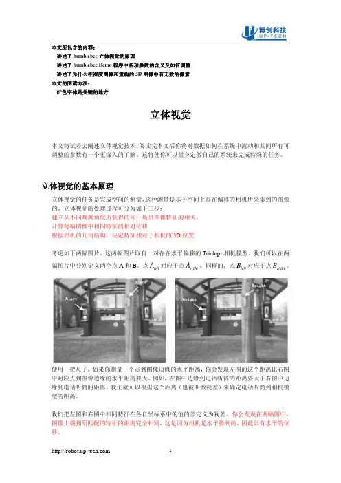
这两幅图片取自一对存在水平偏移的Triclops 相机模型。
我们可以在两幅图片中分别定义两个点A 和B 。
点left A 对应于点right A ,同样的,点left B 对应于点right B 。
使用一把尺子,如果你测量一个点到图像边缘的水平距离,你会发现左图的这个距离比右图中对应点到图像边缘的水平距离要大。
例如,左图中边缘到电话听筒的距离要大于右图中边缘到电话听筒的距离。
我们就可以根据这个距离(也被叫做视差)来确定电话听筒到相机模型的距离。
我们把左图和右图中相同特征在各自坐标系中的值的差定义为视差。
你会发现在两幅图中,图像上端到所匹配的特征的距离完全相同,这是因为相机是水平排列的,因此只有水平的位移。
于是特征A 的视差被定义成D(A) = x(A left ) – x(A right ),B 的则为D(B) = x(B left ) – x(B right ),其中x(A left )是A left 点的x 轴坐标。
如果你去计算D(A) 和D(B),你会发现 D(A) <D(B),这说明在这个场景当中点A 比点B 要远。
建立相关Triclops 库使用绝对相关偏差和的方法来建立图像间的相关。
Software and Hardware Implementations of Stereo Matching1Li Zhou, 2Tao Sun3, Yuanzhi Zhan and 3Jia Wang1School of Information Science and Engineering,Shandong University,P. R. China2Shandong Provincial Key Laboratory of Network based Intelligent Computing,University of Jinan,P. R. China3School of Information Science and Engineering,Shandong UniversityP. R. China1e-mail:******************, 2e-mail:******************AbstractStereo matching is one of the key technologies in stereo vision system due to its ultra high data bandwidth requirement, heavy memory accessing and algorithm complexity. To speed up stereo matching, various algorithms are implemented by different software and hardware processing methods. This paper presents a survey of stereo matching software and hardware implementation research status based on local and global algorithm analysis. Based on different processing platforms, including CPU, DSP, GPU, FPGA and ASIC, analysis are made on software or hardware realization performance, which is represented by frame rate, efficiency represented by MDES, and processing quality represented by error rate. Among them, GPU, FPGA and ASIC implementations are suitable for real-time embedded stereo matching applications, because they are low power consumption, low cost, and have high performance. Finally, further stereo matching optimization technologies are pointed out, including both algorithm and parallelism optimization for data bandwidth reduction and memory storage strategy.Keywords: Stereo Matching, GPU, FPGA, ASIC1. IntroductionThe common ground of stereo vision systems is to model three-dimensional (3D) space and to render 3D objects, using depth information that is the most important element of stereo visionsystems [1]. Stereo matching is one of the most active research topics concerning on the depth information processing capability. It is an important stereo vision technique to extract depth or disparity information from stereo images obtained from slightly different viewpoints, by calculating every pixel’s depth information from stereoscopic images. It is widely used in different applications, such as stereo & feature tracking [2], industrial informatics [3], free-viewpoint video synthesis [4-5], three-dimensional video processing [6], multi-view video coding [7], intelligent robots [8], autonomous vehicles [9] and medicinal image processing [10]. It is forecasted that in 2015 more than 30% of all High Definition (HD) panels at home will be equipped with 3D capabilities [11].Stereo matching quality is restricted by real-time processing capability, high computation and algorithm complexity, high processing bandwidth requirement and high algorithm accuracy. Especially for embedded systems, low power consumption, high processing performance, high resolution, and high flexibility are all required, as well as various duration, frequency, viewing distance, screen size, ambient light, etc., Although the stereo matching problems have been extensively studied during the past decades, it is still difficult to automatically predict high quality depth map because of image noise, textureless regions, consistency and occlusions that are inherent in the captured images or video frames.Because of the reasons mentioned above, stereo matching is still in developing stage. To keep up with consumer electronic development trends, there are two research directions: software optimization and hardware acceleration. In this paper, we present a general comparison survey about software and hardware processing algorithms based on algorithm inherent characteristic, implementations, and architectures. Section II presents an algorithm overview. Section III gives out the software and hardware implementation analysis based on Central Processing Units (CPU), Digital Signal Processors (DSP), Graphic Processing Unit (GPU), Field Programmable Gate Array (FPGA) and Application-Specific Integrated Circuits (ASIC) accelerators. Section IV illustrates the optimization methods. By comparing software and hardware processing method results, section V and VI points out future prospects of stereo matching implementation research direction and conclusion.2. Stereo Matching Algorithms OverviewIn the past two decades, many stereo matching algorithms have been proposed [12]. Categorizes all methods into sparse stereo and dense stereo matching [13]. Categorizes all methods into explicit matching, hand-designed filters and network learning models. The most popular classification till now is global & local method [14].Global approach defines constrained energy models to resolve disparity maps uncertainties. It can be formulated as an energy minimization problem of a Markov RandomField (MRF), simultaneously considering labeling smoothness. Graphic Cut (GC) and Belief Propagation (BP) are two well-known methods. Five of up-to-date top-10-ranked algorithms (with default error threshold equals to 1) are based on the optimized global energy function [15].Although global methods can reach a high quality level with VGA@30 frames per second (fps) performance [16-17], it is still hard for real-time and high resolution application cases because of its computation complexity. Local approach is based on color or intensity patterns within a finite window to determine the disparity. It has less computational complexity and acceptable processing quality, and is more preferred by real-time implementations. That is why the up-to-date real-time stereo applications still largely rely on local methods. The main disadvantages of local methods are noisy results in large un-textured regions and foreground fatting issues at object borders.Besides global and local methods, Semi-Global Matching (SGM) [18] is based on pixel wise matching of Mutual Information (MI). A 2D global smoothness constraint is deduced by combining many 1D constraints. SGM performs an energy minimization in a Dynamic Programming (DP) fashion on multiple 1D path crossing each pixel. Its quality and execution time are in the middle of global and local methods.2.1. BP MethodBP defines a message passing update process to iteratively refine the belief labels for every pixel.A message sent from one pixel to another is updated according to the neighboring messages and energy functions using the simple arithmetic operations. BP algorithm has calculation matrix regularities, but requires a great amount of memory to store messages. The total message size scale is on the order of O(n×L2×T), where n is the number of pixels in the image, L is the number of possible labels (disparity range), and T is the iteration count. Basically it takes O(L2) time to compute each message and there are O(n) messages per iteration. Besides, since each message is processed hundreds of times, the load/store of messages consumes huge memory bandwidth. For example, 1920×1080 image @ 30fps, 300 disparity levels, 8bits every pixel, the BP message storage requirement is about 2.3 GBytes, the processing bandwidth requirement is around 33.9 TB/s for 100 iterations. Even by reducing disparity level to 32, the message passing computation still needs about 8100 billion operations per second. Therefor, message storage, data bandwidth, and computation complexity is the bottleneck of BP algorithm [19]. That is why BP is hard to work on embedded electronic devices, which have limited memory and calculation capability. Different methods are proposed to reduce BP computation complexity and improve processing quality as shown in Table 1. Tree-Re-Weighted message passing (TRW) algorithms [20] is also a message-passing algorithm similar to LBP. The difference is that it computes a lower bound on the energy, and can be implemented using half memory compared with BP.Table 1. BP Algorithm Overview2.2. GC MethodGC minimizes pair wise MRF energies by solving min-cut/max-flow problems on graphic constructions. A graph G = (V; E) is given by a set of vertices V and a set of edges E (sometimes, V is called nodes, E is called links). V usually corresponds to pixels or features extracted from an image, while E encodes spatial relationships. GC also has heavy computational complexity and memory requirements. It takes O(L3) calculation iterations, which increases fast with the number of labels increases. That is why even with the state-ofthe-art numerical optimizers, GC is hard to produce in an acceptable real-time processing manner. GC method yields competitive results, and is proved to be able to handle occlusion reasoning well, but its min-cut technique is used to minimize sub-modular energy that is prone to be a partial labeling problem. Some GC based methods are summarized in Table 2.Table 2. GC Algorithm Overview2.3. DP MethodDP decomposes a problem into a set of sub-problems, then efficiently solves them recursively. It lies in the middle of the spectrum with reasonably matching performance at the expense of relatively large storage memory. Algorithm complexity is O(K×D2), where K is the number of pixels per scan-line, and D is the disparity range. The major problem of DP is that inter-scanline consistency cannot be well enforced, leading to the well-known “streaking” artifacts. Table 3 gives out an overview of various DP based stereo matching methods.Table 3. DP Algorithm Overview2.4. Window Based MatchingWindow based stereo matching algorithm belongs to local matching category. It aggregates matching cost over a given support window. Local window should be large enough to include sufficient intensity variation for matching operation, and be small enough to avoid disparity variation inside the window. Properly designed cost function and selected window type are fundamentals of window based stereo matching method. Fixed window, rectangular window [21], multiple windows [22], adaptive weight (AW) [23], and epipolar geometry-based window [24] and adaptive shape window [25] are proposed in the stereo algorithm.Cost functions designs, such as SAD, rank [26], census [27] transform, are all valid for cost calculation. Rank and census transforms are two nonparametric transforms, depending on the relative order of pixel values rather than the pixel values them. The differences between rank and census method are that rank method counts the number of pixels in a window which is less than the center pixel, while census maps a pixel window to a bit string. Both methods have an algorithmic structure suitable for hardware implementation, and are invariance to certain types of image distortion and noise. Combined with other optimization technique, window based matching algorithms can reach to reasonable quality and performance [23]. computes pixel-wise adaptive support-weights based on proximity and color distances to center pixel. [28] Uses spatio-temporal correlation and temporal variation of the disparity field [29]. Limits search range around the basic line for fast search [30]. Replaces disparity estimation with planes in texture less regions [31]. Introduces partial sum method based on AW to reduce pixels information in a large window.2.5. Affine Transformation MethodScale Invariant Feature Transform (SIFT) method [59] can extract distinctive invariant features from images that are invariant to image scale, rotation, 3D viewpoint, noise, illumination change, and match densely pixel-wise SIFT features between two images while preserving spatial discontinuities [60]. Affine-SIFT (ASIFT) [61] can identify features that undergo very large affine distortions. However, the huge amount of computations required by multiple cascaded transformations makes SIFT difficult to achieve real-time performance [62]. Presents an overview of SIFT approaches based on general purpose multi-core processors, customized multi-core processor and FPGA implementation.Phase Singularity (PS) represents to a point where a complex signal equals to zero. In stereo matching, PS is estimated by convolving images with complex filters. Compared with SIFT method, PS-based approaches have the advantage of robustness against variations in luminance and imbalance between stereo image sensors at the cost of higher computing resource requirements [63, 64]. Combines PS with SIFT, which can get higher repeatability rates.2.6. Other Intelligence MethodNeural based method can also reach a reasonable stereo matching quality [15]. Its most distinct characteristic is that it does not require matching between left and right elements. Instead, the binocular stimuli with a specific disparity are matched with binocular neurons in the form of neuronal responses. Different neurons with different preferred weights patterns can indicate the spatial left and right receptive fields. Thus, the response of a neuron indicates a matching degree of two receptive fields [13]. Firstly presents a neurotrophic and spatiotemporal regression model of the laminar cortex architecture for stereo that is able to perform stereo disparity detection competitively with sub-pixel precision. In [65], a multi-layer inplace learning network was used to detect binocular disparities. Fuzzy set theory also can be used to deal with stereo matching [66]. Proposes a threshold-based segmentation to build interval-valued fuzzy sets [67]. Adapts biologically Disparity Energy Model to separate stereo populations, then trains these populations, and extracts disparity values in entire scenes.3. Software and Hardware Processing of Stereo Matching MethodsIn the past decades, with stereo consumer application market flourishing, researchers are devoting more efforts to real-time software and hardware system design for stereo matching. Although High Performance Computing (HPC) can provide considerable computational power, there are still many implementation challenges of stereo matching:●Ultra high computation complexity: searching all pixel candidacies within an area space needstens of iterations to find the best matching point, calculates all candidacies matching cost with matrix multiplication or addition. Sub-pixel or higher dynamic disparity range case is even worse. These factors lead to ultra high computation complexity cost.●Ultra high data bandwidth and on-chip SRAM size requirement: are caused by massivetemporary data exchanging required by algorithms. However, memory is always the bottleneck for all systems. Optimized data reuse, parallelization, or hierarchical schemes should be researched for memory related issues.●Real time processing and low power consumption requirement: needs advanced acceleratorprocessing schemes with both power consumption and high processing performance. The real-time and power issue will be existing for a long time because processing requirement is increasingly faster than processing capability.●Irregular algorithm parameter selection and additional pre-/post-processing steps: needs tobe carefully considered to resolve occlusion, inconsistent, or irregular issues in stereo matching algorithm.To resolve the above requirement and bottlenecks, strives needed in three directions: algorithms optimization, software acceleration and hardware acceleration. Software accelerator evolves in parallel optimization on CPU, DSP, and GPU. Hardware accelerators are based on FPGA or ASIC.3.1. CPU ImplementationCPU has the highest flexibility for stereo matching algorithms, but it has a limited acceleration for real-time calculation of dense disparity map because CPU has less specific acceleration processing unit. Early research work [50] only achieves non-video rate performance due to limited computing power [68]. Firstly implements software processing with low bit depth motion estimation algorithms for outdoor robot navigation [69]. Proposes a real-time stereo depth extraction method for an intelligent home assistant robot. [70] is able to achieve approximately 17fps on 640 × 480 images with 25 disparity range on a 2 GHz dualcore processor.3.2. DSP ImplementationDSP has better signal processing capability because of better data processing architectures, lower cost and less power consumption than CPU. Although DSP can reach reasonable stereo matching performance, it has inherent disadvantages, such as data word alignment, bandwidth throughput issue, etc. Consequently, high quality algorithm is seldom realized by a DSP system and is only limited to window based algorithms. With powerful multimedia accelerators, high system clock frequency, optimized cache usage and interconnections between cores, multi-core processor is an effective way to increase stereo matching performance [71]. However, simply increasing the number of processing elements comes with the cost of higher power consumption. In addition, there is no linear relationship between the number of processor cores and the processing performance. As a result, the GPU architecture appeared.3.3. GPU ImplementationGPU integrates hundreds of extremely powerful computation stream Processing Elements (PE) simultaneously, emphasizing coherent memory access, memory locality, and efficiency of data parallelism, with powerful floating-point arithmetic intensity and high memory bandwidth. For example, nVidia Tesla S1070 contains four GT200 processors, each has 240 PEs, and each processor provides about one Tera Flop (TF) of single-precision throughput over 100 GB/s memory bandwidth. As a comparison, 3.2 GHz Intel Core 2 Extreme can only operate at roughly 51.2 Gega Flops per second (GF/s). Some other GPU processing system, such as AMD FireGL, Qualcomm Snapdragon, and ST Ericsson’s U8500 are also widely used in PC or embedded systems. Software programming models, such as CUDA, OpenGL, and DirectX, are also developed by NVidia/AMD/Intel to assist General-Purpose Computation on GPU (GPGPU) programming for a broader community of application developers. Most stereo matching tasks perform the same computation on a number of pixels in parallel. So GPU stereo matching implementations are drawn much attention and obtained desirable speedup, which is benefited from GPU’s hundreds of PEs and high-level software development platform. It is crucial to design application-specific GPU stream kernels and exploit the inherent parallelism of algorithms to adapt GPU’s parallelcomputation core. Tradeoff should be sufficiently considered between accelerating speed and accuracy. With the rapid development of GPU architecture, there should be sufficient potential margin for GPU based stereo matching optimization.3.4. FPGA/ASIC ImplementationBesides previously discussed software methods, dedicated FPGA/ASIC hardware approaches have more computation capability, and their costs are relatively lower. FPGA or ASIC is very suitable for pixel-wise operations, especially for the intensive complexity computational requirement of stereo matching methods. Differences between FPGA and ASIC implementations are that ASIC implementation needs IC design and implementation technology such as IC foundry United Microelectronics Corporation (UMC) and long development cycles, while FPGA implementation has reconfiguration capability with requiring more power and area consumption than dedicated ASIC chip. Thanks to increased hardware calculation capability, the performance of some FPGA or ASIC implementations are close to real-time processing for high quality stereo algorithms (GC, DP, or BP) with limited image resolution [72]. Gives a hardware processing comparison for FPGA and ASIC design, and presents powerful real-time vision engine in a single chip which integrates optical flow (with 1810 parallel PEs), stereo (with 1145 parallel PEs) and several local image feature extraction methods together FPGA or ASIC implementations have the following features.●Parallel PE arrays: integrated into a signal chip. Each of the PE works parallel, focusing onspecific algorithm execution to speed up the whole algorithm execution.●Dedicated pipeline architecture: based on corresponding calculation progresses, dedicatedpipeline architecture can improve chip clock frequency and execution efficiency, but with higher system design complexity. So there is a trade-off between execution performance and architecture complexity.●Data reuse and memory allocation technique: heterogeneous processor’s bottleneck is dataexchanging for both off/on-chip memory. Data reuse strategy is tightly related with memory reuse and allocation method. It is critical to reduce system internal storage size, computation resource, and bandwidth requirement.From the bandwidth’s point of view, a high-end SoC with a fairly wide 128-bit bus can only support about 4GB/s bandwidth even with 50 percent bus utilization and 500MHz bus frequency. That is far below the maximum memory requirement of stereo matching. From processing performance’s point of view, parallel data reuse method can increase performance and decrease memory bandwidth requirements, but it increases on-chip SRAM size and system cost. Therefore, the implementation of FPGA or ASIC calls for much attention on smart strategies for the selection between on-chip memory size and memory bandwidth.4. Software and Hardware Processing Method ComparisonFrom CPU, DSP, GPU, to FPGA, ASIC, the processing performance increases sequentially, while cost and power consumption decreases correspondingly. Software methods have more flexibility andshorter development cycle, while hardware implementation needs longer design cycle with less design flexibility because of simultaneous consideration of algorithm optimization and hardware mapping issues. From the point view of practicality, hardware stereo processing system should be more acceptable for a real-time stereo vision system because of its lower cost and lower power consumption.Stereo matching accuracy and speed evaluation are two critical points for stereo matching methods. Accuracy can be evaluated by the error rate, which is the average percentage of bad pixels of four benchmark data sets (Tsukuba, Venus, Teddy, and Cones). Speed is measured by system throughput, mainly including Millions of Disparity Estimations per Second (MDE/s), number of GF/s, and fps. To clearly indicate the differences between algorithms and processing platforms, software and hardware implementation comparisons for BP, DP and local stereo matching algorithms are shown in Table 4-6.Although GC has higher quality, it is hard to reach the real-time requirement, and is seldom implemented by GPU, FPGA or ASIC accelerator. [104] proposes an early termination rule and prioritizing swap pair search order, and can reach 24.73s for Tsukuba image on Intel Core2Quad Q6600, 4G RAM [105]. Implements a reduced GC method where only some potential values in the disparity range are selected for each pixel, and can reach 83s for Tsukuba image on Intel 3.2 GHz P4 processor, 512 MB RAM.Based on above comparisons, CPU and DSP are not suitable for real-time embedded applications. GPU, FPGA or ASIC have more advantages compared to CPUs, DSPs for their low power consumption and low cost embedded application systems. BP-based algorithms perform high image quality, but suffer from high computational complexity and memory storage requirement. They are more suitable to be accelerated by hardware. BP searches for an optimal solution of the entire image and requires multiple iterations; however DP uses a single pass to calculate the global optimal solution for each scan-line independently. As a result, DP-based approaches are faster and can generate disparity maps more quickly, but estimation results are prone to error with horizontal streaks in the generated disparity maps because of the difficulties in enforcing inter scan-line consistency by 1-D scan line process. Window based algorithms have higher processing speed because of lower data bandwidth and less computation complexity, but matching errors are higher. For the same algorithm, generally, the processing speed, quality and power consumption of FPGA or ASIC can outperform GPU accelerator generally, as proved by [80-91]. The disadvantages of FPGA or ASIC are longer developing time and less processing flexibility compared with GPU.Table 4. Software and Hardware ProcessingAlgorithmsTable 5. Software and Hardware Processing Overview of Optimized DP AlgorithmsTable 6. Software and Hardware Processing Overview of Optimized WindowBased Algorithms5. Future Research DirectionTo improve system throughput with better disparity accuracy is still a challenging research topic although a number of near real-time systems which can achieve higher image resolution which have been implemented on GPU, FPGA or ASIC. For future software and hardware implementations, there are several points need to be emphasized:●Super Resolution (SR) stereo vision processing: data bandwidth and memory storagerequirements will be much tighter than current high resolution steam. New optimization methods should be considered during software and hardware optimization processes.●Real-time and low power consumption requirements: the trend for hand-held stereo visionsystem with high image resolution, quality, and free-view features. Algorithm parallelization and specific PE design are effective technologies for it.●Powerful GPU, FPGA and ASIC system optimization: will play more critical roles along withVLSI design technology development. Parallel calculation capability, specific PE, efficient memory allocation method, will bring stereo vision system a revolution in the near future. To resolve issues including occlusion, image inconsistent, hardware resource limitations, etc., there are several optimization aspects to meet the upcoming stereo matching technology challenges.5.1. Image Segmentation or Hierarchy OptimizationSegmentation or hierarchy approach has been widely employed in stereo matching to reduce algorithm complexity. It can be divided into three categories: over segmentation, color segmentation and coarse-to-fine layer department. They break the image apart into smaller ones,and then process the reduced images one by one. Color based segment assumes that the neighboring pixels with similar colors have similar depth values. Over segment gets trade-off between color segment and performance. Coarse-to-fine can reduce disparity calculation range by hierarchy search.We also study the optimization method based on adaptive image segmentation [106]. We take advantages of chrominance component, intelligently comprehends object depth characteristics to pre-determine the inter-prediction block size, instead of selecting the best one after calculating all block sizes’ cost function. Ignoring unrelated block size calculation saves computation resources and time. Smaller block size is pre-decided at an object boundary, and larger block size is for consecutive areas. Experiment results show that the method not only is effective for real-time stereo matching, but also performs well on both object boundary and consecutive areas, both block effect and prediction noises are optimized with accelerated prediction speed.5.2. Occlusion and Consistency HandlingStereo image discontinuous issues mainly include occlusion and color inconsistency. Occlusion is caused by viewing degree changes between images. Image inconsistency is always caused by various radiometric factors such as luminance changes, illuminate color or imaging device changes. Some optimization methods, such as left-right consistency criterion, interactively estimation, are already in use to identify and remove invalid matches or occlusion pixels. Normalized or unified matching algorithm [107] and Scan-line Optimization (SO) [108] are effective optimization techniques for image inconsistency issues. Depth map mismatches can be suppressed by penalizing large jumps in disparity between the scan-line points, or only dealing with propagated disparities along scan-line directions.5.3. Matching Cost & Energy Optimization ImprovementA careful selection of cost functions or energy optimization methods is the foundation of local or global stereo matching algorithms [109]. compares a large scale possible combination of matching costs with window based method, SGM, and GC under various radiometric conditions. High order MRF model [110], Quadratic Pseudo-Boolean Optimization (QPBO) approaches [111], or high order strategy [112], Mutual Information (MI) [113], Winner-TakeAll (WTA) [115] are all valid for efficient energy optimization. Cost function optimizations have always been used in a cooperative system to reduce computation redundancy.5.4. Cooperative OptimizationHigh quality stereo matching results are always involved in combined processing methods. Integration of HBP, mean sift, color segmentation [116], combination of shiftable windows and global energy minimization framework [117], combination of WTA and DP [118], diffuses of matching costs and weights [119], integration of WTA and matching cost [120], combination of GC and SIFT [121], associated matching cost optimization and occlusion handling [114], integrated census transform and hamming distance calculation [91], as well as combined optical flow and feature extraction [122] are all examples of cooperation. Stereo matching precision enhancement,。
双眼视觉和立体视觉
在某些哺乳动物如牛、马、羊等,它们的两眼长在头的两侧,因此两眼的视野完全不重叠,左眼和右眼各自感受不同侧面的光刺激,这些动物仅有单眼视觉(monocular vision)。
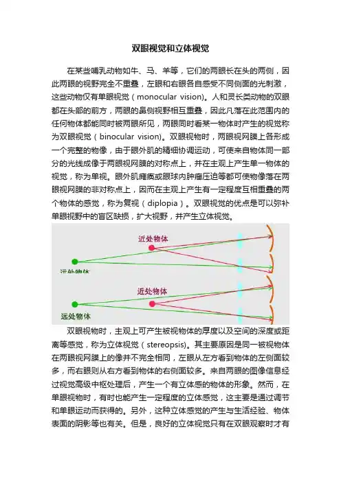
人和灵长类动物的双眼都在头部的前方,两眼的鼻侧视野相互重叠,因此凡落在此范围内的任何物体都能同时被两眼所见,两眼同时看某一物体时产生的视觉称为双眼视觉(binocular vision)。
双眼视物时,两眼视网膜上各形成一个完整的物像,由于眼外肌的精细协调运动,可使来自物体同一部分的光线成像于两眼视网膜的对称点上,并在主观上产生单一物体的视觉,称为单视。
眼外肌瘫痪或眼球内肿瘤压迫等都可使物像落在两眼视网膜的非对称点上,因而在主观上产生有一定程度互相重叠的两个物体的感觉,称为复视(diplopia)。
双眼视觉的优点是可以弥补单眼视野中的盲区缺损,扩大视野,并产生立体视觉。
双眼视物时,主观上可产生被视物体的厚度以及空间的深度或距离等感觉,称为立体视觉(stereopsis)。
其主要原因是同一被视物体在两眼视网膜上的像并不完全相同,左眼从左方看到物体的左侧面较多,而右眼则从右方看到物体的右侧面较多。
来自两眼的图像信息经过视觉高级中枢处理后,产生一个有立体感的物体的形象。
然而,在单眼视物时,有时也能产生一定程度的立体感觉,这主要是通过调节和单眼运动而获得的。
另外,这种立体感觉的产生与生活经验、物体表面的阴影等也有关。
但是,良好的立体视觉只有在双眼观察时才有
可能。

双目视觉简介双目立体视觉,在百度百科里的解释是这样解释的:双目立体视觉(Binocular Stereo Vision)是机器视觉的一种重要形式,它是基于视差原理并利用成像设备从不同的位置获取被测物体的两幅图像,通过计算图像对应点间的位置偏差,来获取物体三维几何信息的方法。
我相信未来的世界一定是三维感知的世界,毕竟二维世界很多情况下不能满足要求的,一视差 Disparity与深度图那么提到双目视觉就不得不提视差图:双目立体视觉融合两只眼睛获得的图像并观察它们之间的差别,使我们可以获得明显的深度感,建立特征间的对应关系,将同一空间物理点在不同图像中的映像点对应起来,这个差别,我们称作视差(Disparity)图像。
对于视差的理解自己可以体验一下:将手指头放在离眼睛不同距离的位置,并轮换睁、闭左右眼,可以发现手指在不同距离的位置,视觉差也不同,且距离越近,视差越大。
那么提到视差图,就有深度图,深度图像也叫距离影像,是指将从图像采集器到场景中各点的距离(深度)值作为像素值的图像。
获取方法有:激光雷达深度成像法、计算机立体视觉成像、坐标测量机法、莫尔条纹法、结构光法。
那么这里引申一下深度图与点云的区别,点云:当一束激光照射到物体表面时,所反射的激光会携带方位、距离等信息。
若将激光束按照某种轨迹进行扫描,便会边扫描边记录到反射的激光点信息,由于扫描极为精细,则能够得到大量的激光点,因而就可形成激光点云。
深度图像经过坐标转换可以计算为点云数据;有规则及必要信息的点云数据可以反算为深度图像。
两者在一定条件下是可以相互转化的,之前的博客里,有使用PCL库实现过点云提取深度图,当然给出相机参数也是可以由深度图转为点云的。
截图一个深度图:所以深度与视差的关系如下比如绝对差值法绝对差值图的计算方法如下:D=|L-R|式中,L、R和D分别代表左视图、右视图和对应的绝对差值图的亮度值。
绝对差值图并不是严格意义上的视差图,但是它的计算方法最为简单,速度快,它给出的结果可以作为参考那么我们知道视差又有另外一个概念就是UV-disparity mapping,简单的给个图表示:是怎么得到这个结果的呢?原来是统计统计视差的个数,比如V-disparity Map中的第一行分别统计视差为0,1,2,3,4,5的个数,所以得到了V-disparity Map的第一行分别为0,2,0,1,1,1,那么在真实的图喜爱那个中得到的结果如下:那么利用视差可以做很多有用的功能,比如列举一篇文章UV disparity based obstacle detection and pedestrian classification in urban traffic scenarios二 Raysray就是连接图像上一点到光心形成的一条射线。
双目视觉成像原理1.引言双目立体视觉(Binocular Stereo Vision)是机器视觉的一种重要形式,它是基于视差原理并利用成像设备从不同的位置获取被测物体的两幅图像,通过计算图像对应点间的位置偏差,来获取物体三维几何信息的方法。
融合两只眼睛获得的图像并观察它们之间的差别,使我们可以获得明显的深度感,建立特征间的对应关系,将同一空间物理点在不同图像中的映像点对应起来,这个差别,我们称作视差(Disparity)图。
双目立体视觉测量方法具有效率高、精度合适、系统结构简单、成本低等优点,非常适合于制造现场的在线、非接触产品检测和质量控制。
对运动物体(包括动物和人体形体)测量中,由于图像获取是在瞬间完成的,因此立体视觉方法是一种更有效的测量方法。
双目立体视觉系统是计算机视觉的关键技术之一,获取空间三维场景的距离信息也是计算机视觉研究中最基础的内容。
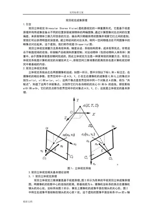
2.双目立体视觉系统立体视觉系统由左右两部摄像机组成。
如图一所示,图中分别以下标L和r标注左、右摄像机的相应参数。
世界空间中一点A(X,Y,Z)在左右摄像机的成像面C L和C R上的像点分别为al(ul,vl)和ar(ur,vr)。
这两个像点是世界空间中同一个对象点A的像,称为“共轭点”。
知道了这两个共轭像点,分别作它们与各自相机的光心Ol和Or的连线,即投影线alOl和arOr,它们的交点即为世界空间中的对象点A(X,Y,Z)。
这就是立体视觉的基本原理。
图1:立体视觉系统3.双目立体视觉相关基本理论说明3.1 双目立体视觉原理双目立体视觉三维测量是基于视差原理,图2所示为简单的平视双目立体成像原理图,两摄像机的投影中心的连线的距离,即基线距为b。
摄像机坐标系的原点在摄像机镜头的光心处,坐标系如图2所示。
事实上摄像机的成像平面在镜头的光心后,图2中将左右成像平面绘制在镜头的光心前f处,这个虚拟的图像平面坐标系O1uv的u轴和v 轴与和摄像机坐标系的x 轴和y 轴方向一致,这样可以简化计算过程。

《基于双目立体视觉的测量技术研究》一、引言随着计算机视觉技术的飞速发展,双目立体视觉技术在各个领域的应用日益广泛。
双目立体视觉技术基于人类双眼的视觉原理,通过对两个不同视角的图像进行立体匹配和计算,实现对物体三维信息的获取和测量。
本文将详细介绍基于双目立体视觉的测量技术的研究背景、意义及现状,并探讨其在实际应用中的优势和挑战。
二、双目立体视觉技术概述双目立体视觉技术是通过模拟人类双眼的视觉过程,利用两个相机从不同角度拍摄同一场景,获取两幅具有一定视差的图像。
通过对这两幅图像进行立体匹配和计算,可以获得物体在三维空间中的位置、形状和尺寸等信息。
该技术具有非接触、高精度、高效率等优点,广泛应用于机器人导航、三维重建、工业检测等领域。
三、双目立体视觉测量技术原理双目立体视觉测量技术的核心是立体匹配。
首先,通过相机标定获取相机的内外参数,包括相机的焦距、光心位置、畸变系数等。
然后,对两幅图像进行预处理,如去噪、平滑等操作,以提高匹配的准确性。
接着,采用立体匹配算法对两幅图像进行匹配,获取视差图。
最后,通过视差图和相机参数计算得到物体的三维信息。
四、双目立体视觉测量技术研究现状目前,双目立体视觉测量技术已取得了一系列研究成果。
在算法方面,研究者们提出了多种立体匹配算法,如基于区域的方法、基于线或面的方法、基于特征的方法等。
这些算法在提高匹配精度和速度方面取得了显著成果。
在应用方面,双目立体视觉技术已广泛应用于机器人导航、工业检测、三维重建、医疗影像处理等领域。
然而,在实际应用中仍存在一些问题,如匹配算法的鲁棒性、测量精度的提高等。
五、基于双目立体视觉的测量技术优势与挑战基于双目立体视觉的测量技术具有以下优势:一是非接触式测量,不会对被测物体造成损伤;二是高精度和高效率,能够快速获取物体的三维信息;三是适用范围广,可应用于各种场景和领域。
然而,该技术也面临一些挑战:一是算法的鲁棒性问题,如光照变化、噪声干扰等因素会影响匹配精度;二是测量精度的提高问题,如何进一步提高测量精度以满足更高要求的应用场景;三是实时性问题,如何实现快速准确的测量以满足实时性要求。
双目视觉测量原理Stereo vision, also known as binocular vision, refers to the ability to perceive depth and three-dimensional structures by integrating the different images received by the left and right eyes. This is made possible by the brain using the differing signals received by each eye to calculate the distance and position of objects in the visual field. 双目视觉是指通过左右眼接收到的不同图像来感知深度和三维结构的能力。
这是通过大脑利用每只眼睛接收到的不同信号来计算视野中物体的距离和位置。
One of the key principles behind stereo vision is triangulation, wherein the brain uses the slight differences in the images receivedby the left and right eyes to calculate the distance to objects in the field of view. This is similar to the way in which surveyors use triangulation to measure distances and map out landscapes. 双目视觉的一个关键原理是三角测量,大脑利用左右眼接收到的图像之间的微小差异来计算视野中物体的距离。
这类似于测量员使用三角测量来测量距离和绘制出景观的方式。
双目立体视觉的概念与分析作者:王青伟来源:《中国科技术语》2014年第07期摘要:双目立体视觉是在对人类视觉系统研究的基础上,通过双目图像的处理来获取物体三维几何信息,其结果表现为深度图,再经过进一步处理得到三维空间中的物体信息的方法。
双目立体视觉的研究具有重要的应用价值,包括机器人的自主导航、工业检测、视觉监控以及车辆辅助驾驶系统等。
随着计算机硬件的高速发展,基于双目立体视觉的应用越来越多地呈现在人们面前。
关键词:双目立体视觉,立体匹配,相机标定中图分类号:N04;O43;TP3 文献标识码:A 文章编号:1673-8578(2014)S1-0070-03 The Concept and Analysis of Binocular Stereo VisionWANG QingweiAbstract:Binocular stereo vision is one method which can obtain the 3D information by processing two images from the cameras. The 3D information is presented by depth image. The stereo vision system can be used in auto navigation, industrial detection, visual surveillance, and drive assistance system. With the rapid evolution of hardware, binocular vision based application will become more and more popular.Keywords: binocular stereo vision, stereo matching, camera calibration收稿日期:2014-06-28作者简介:王青伟(1977—),女,辽宁本溪人,博士,实审审查员,从事自动控制领域的专利审查。
计算机双目立体视觉双目立体视觉技术是仿照人类利用双目线索感知深度信息的方法,实现对三维信息的感知。
为解决智能机器人抓取物体、视觉导航、目标跟踪等奠定基础。
双目立体视觉(Binocular Stereo Vision )是机器视觉的一种重要形式,它是基于视差原理并利用成像设备从不同的位置获取被测物体的两幅图像,通过计算图像对应点之间的位置偏差,来获取物体三维几何信息的方法。
融合两只眼睛获取的图像并观察它们之间的差别,使我们可以获得明显的深度感,建立特征间的对应关系,将同一空间物理点在不同图像中的映像点对应起来,这个差别,我们称作为视差(Disparity )图像。
双目立体视觉系统立体视觉系统由左右两部摄像机组成,如图,世界空间中的一点A(X,Y ,Z)在左右摄像机的成像面1C 和r C 上的像点分别为)(111,v u a 和)(r r r v u a ,。
这两个像点是世界空间中同一个对象点A 的像,称为“共轭点”。
知道了这两个共轭像点,分别作它们与各自相机的光心1O 和r O 的连线,即投影线11O a 和r r O a ,它们的交点即为世界空间中的对象点A 。
这就是立体视觉的基本原理。
双目立体视觉智能视频分析技术恢复场景的3D 信息是立体视觉研究中最基本的目标,为实现这一目标,一个完整的立体视觉系统通常包含六个模块:图像获取、摄像机标定、特征提取、立体匹配、三维恢复和视频分析(运动检测、运动跟踪、规则判断、报警处理)。
图像获取(Image Acquisition )数字图像的获取是立体视觉的信息来源。
常用的立体视觉图像一般为双目图像,有的采用夺目图像。
图像的获取方式有很多种,主要有具体运用的场合和目的决定。
立体图像的获取不仅要满足应用要求,而且考虑视点差异、光照条件、摄像机的性能和场景特点等方面的影像。
摄像机标定(Camera Calibration )图像上每一点的亮度反映了空间物体表面某点反射光的强度,而该点在图像上的位置则与空 间物体表面相应点的几何位置有关。
科技资讯2016 NO.02SCIENCE & TECHNOLOGY INFORMATION信 息 技 术13科技资讯 SCIENCE & TECHNOLOGY INFORMATION 人类获取外界世界的信息70%来源于视觉系统。
视觉是人们观察、认识世界的主要手段。
当人分别用左眼和右眼去看同一个东西时,物件的距离和空间感会变得不一样。
这是因为人体的两只眼睛位置不同,令每只眼睛看出来的影像有所差异。
当左右眼睛同时看东西时,所看到的影像传到脑部时,脑部会将两个影像合二为一,形成对物体的立体和空间感,即双目立体视觉。
双目立体视觉系统就是利用视差原理通过成像设备获取被测物不同位置的两幅图像,利用计算机对这两幅图像进行图像处理,计算图像对应点的位置偏差,恢复和重建被测物三维几何信息。
它融合两只眼睛获得的图像并观察它们之间的差别,可以获得明显的深度感,即可计算出物件的三维几何信息。
1 双目立体视觉系统双目立体视觉系统由双目摄像机、图像采集卡和计算机组成。
双目摄像机包括两个摄像头,可以从不同的位置采集被测物的两幅图像。
图像采集卡是双目摄像机和计算机之间的桥梁,图像采集卡可以将双目摄像机采集到的图像信号转换成数字信号传输给计算机,并保存在计算机的硬盘里。
计算机是图像处理的中心,主要通过算法完成。
通过图像预处理、图像分割、特征提取、立体匹配等图像算法处理,解算出被测图的三维几何信息,同时进行三维场景的重建。
2 双目立体视觉原理当一个摄像机拍摄图像时,由于图像中的像素点坐标相对于真实的世界坐标并不是唯一的,会造成深度信息的丢失。
融合两只眼睛获得的图像并观察它们的差别,可以获得明显的深度感。
因此,使用双目摄像机的两个摄像头同时拍摄同一场景,可以得到两幅图像,通过两幅图像的差别就可以获取三维世界坐标中的深度信息。
如图1所示,真实三维空间中任意一点P (X W ,Y W ,Z W ),通过一个摄像机成像以后可以得到P 点在成像平面上的投影点A 1(X 1,Y 1),摄像机光心为O 1点。
人眼立体视觉原理The principle of stereoscopic vision in human eyes is one of the marvels of nature. 人眼立体视觉原理是自然界的奇迹之一。
It is the ability of the human visual system to perceive depth and three-dimensional structure from the two-dimensional retinal images in our eyes, allowing us to see the world in all its depth and beauty. 这是人类视觉系统从眼睛中的二维视网膜图像中感知深度和三维结构的能力,使我们能够看到世界的深度和美丽。
The process of stereoscopic vision begins with the eyes capturing two slightly different images of the same scene, due to their separation by a few inches. 立体视觉的过程始于眼睛捕捉到同一场景的两幅略有不同的图像,这是由于它们相互相隔几英寸。
These images are then sent to the brain, which processes the information to create a single, three-dimensional image. 然后这些图像被发送至大脑,大脑处理这些信息,创造出一个单一的三维图像。
The human brain uses a process called binocular disparity to merge the two separate images from each eye into a single, unified 3D image. 人脑使用一种叫做双眼差异的过程,将每只眼睛的两个独立图像合并成一个统一的三维图像。
Software and Hardware Implementations of Stereo Matching1Li Zhou, 2Tao Sun3, Yuanzhi Zhan and 3Jia Wang1School of Information Science and Engineering,Shandong University,P. R. China2Shandong Provincial Key Laboratory of Network based Intelligent Computing,University of Jinan,P. R. China3School of Information Science and Engineering,Shandong UniversityP. R. China1e-mail:******************, 2e-mail:******************AbstractStereo matching is one of the key technologies in stereo vision system due to its ultra high data bandwidth requirement, heavy memory accessing and algorithm complexity. To speed up stereo matching, various algorithms are implemented by different software and hardware processing methods. This paper presents a survey of stereo matching software and hardware implementation research status based on local and global algorithm analysis. Based on different processing platforms, including CPU, DSP, GPU, FPGA and ASIC, analysis are made on software or hardware realization performance, which is represented by frame rate, efficiency represented by MDES, and processing quality represented by error rate. Among them, GPU, FPGA and ASIC implementations are suitable for real-time embedded stereo matching applications, because they are low power consumption, low cost, and have high performance. Finally, further stereo matching optimization technologies are pointed out, including both algorithm and parallelism optimization for data bandwidth reduction and memory storage strategy.Keywords: Stereo Matching, GPU, FPGA, ASIC1. IntroductionThe common ground of stereo vision systems is to model three-dimensional (3D) space and to render 3D objects, using depth information that is the most important element of stereo visionsystems [1]. Stereo matching is one of the most active research topics concerning on the depth information processing capability. It is an important stereo vision technique to extract depth or disparity information from stereo images obtained from slightly different viewpoints, by calculating every pixel’s depth information from stereoscopic images. It is widely used in different applications, such as stereo & feature tracking [2], industrial informatics [3], free-viewpoint video synthesis [4-5], three-dimensional video processing [6], multi-view video coding [7], intelligent robots [8], autonomous vehicles [9] and medicinal image processing [10]. It is forecasted that in 2015 more than 30% of all High Definition (HD) panels at home will be equipped with 3D capabilities [11].Stereo matching quality is restricted by real-time processing capability, high computation and algorithm complexity, high processing bandwidth requirement and high algorithm accuracy. Especially for embedded systems, low power consumption, high processing performance, high resolution, and high flexibility are all required, as well as various duration, frequency, viewing distance, screen size, ambient light, etc., Although the stereo matching problems have been extensively studied during the past decades, it is still difficult to automatically predict high quality depth map because of image noise, textureless regions, consistency and occlusions that are inherent in the captured images or video frames.Because of the reasons mentioned above, stereo matching is still in developing stage. To keep up with consumer electronic development trends, there are two research directions: software optimization and hardware acceleration. In this paper, we present a general comparison survey about software and hardware processing algorithms based on algorithm inherent characteristic, implementations, and architectures. Section II presents an algorithm overview. Section III gives out the software and hardware implementation analysis based on Central Processing Units (CPU), Digital Signal Processors (DSP), Graphic Processing Unit (GPU), Field Programmable Gate Array (FPGA) and Application-Specific Integrated Circuits (ASIC) accelerators. Section IV illustrates the optimization methods. By comparing software and hardware processing method results, section V and VI points out future prospects of stereo matching implementation research direction and conclusion.2. Stereo Matching Algorithms OverviewIn the past two decades, many stereo matching algorithms have been proposed [12]. Categorizes all methods into sparse stereo and dense stereo matching [13]. Categorizes all methods into explicit matching, hand-designed filters and network learning models. The most popular classification till now is global & local method [14].Global approach defines constrained energy models to resolve disparity maps uncertainties. It can be formulated as an energy minimization problem of a Markov RandomField (MRF), simultaneously considering labeling smoothness. Graphic Cut (GC) and Belief Propagation (BP) are two well-known methods. Five of up-to-date top-10-ranked algorithms (with default error threshold equals to 1) are based on the optimized global energy function [15].Although global methods can reach a high quality level with VGA@30 frames per second (fps) performance [16-17], it is still hard for real-time and high resolution application cases because of its computation complexity. Local approach is based on color or intensity patterns within a finite window to determine the disparity. It has less computational complexity and acceptable processing quality, and is more preferred by real-time implementations. That is why the up-to-date real-time stereo applications still largely rely on local methods. The main disadvantages of local methods are noisy results in large un-textured regions and foreground fatting issues at object borders.Besides global and local methods, Semi-Global Matching (SGM) [18] is based on pixel wise matching of Mutual Information (MI). A 2D global smoothness constraint is deduced by combining many 1D constraints. SGM performs an energy minimization in a Dynamic Programming (DP) fashion on multiple 1D path crossing each pixel. Its quality and execution time are in the middle of global and local methods.2.1. BP MethodBP defines a message passing update process to iteratively refine the belief labels for every pixel.A message sent from one pixel to another is updated according to the neighboring messages and energy functions using the simple arithmetic operations. BP algorithm has calculation matrix regularities, but requires a great amount of memory to store messages. The total message size scale is on the order of O(n×L2×T), where n is the number of pixels in the image, L is the number of possible labels (disparity range), and T is the iteration count. Basically it takes O(L2) time to compute each message and there are O(n) messages per iteration. Besides, since each message is processed hundreds of times, the load/store of messages consumes huge memory bandwidth. For example, 1920×1080 image @ 30fps, 300 disparity levels, 8bits every pixel, the BP message storage requirement is about 2.3 GBytes, the processing bandwidth requirement is around 33.9 TB/s for 100 iterations. Even by reducing disparity level to 32, the message passing computation still needs about 8100 billion operations per second. Therefor, message storage, data bandwidth, and computation complexity is the bottleneck of BP algorithm [19]. That is why BP is hard to work on embedded electronic devices, which have limited memory and calculation capability. Different methods are proposed to reduce BP computation complexity and improve processing quality as shown in Table 1. Tree-Re-Weighted message passing (TRW) algorithms [20] is also a message-passing algorithm similar to LBP. The difference is that it computes a lower bound on the energy, and can be implemented using half memory compared with BP.Table 1. BP Algorithm Overview2.2. GC MethodGC minimizes pair wise MRF energies by solving min-cut/max-flow problems on graphic constructions. A graph G = (V; E) is given by a set of vertices V and a set of edges E (sometimes, V is called nodes, E is called links). V usually corresponds to pixels or features extracted from an image, while E encodes spatial relationships. GC also has heavy computational complexity and memory requirements. It takes O(L3) calculation iterations, which increases fast with the number of labels increases. That is why even with the state-ofthe-art numerical optimizers, GC is hard to produce in an acceptable real-time processing manner. GC method yields competitive results, and is proved to be able to handle occlusion reasoning well, but its min-cut technique is used to minimize sub-modular energy that is prone to be a partial labeling problem. Some GC based methods are summarized in Table 2.Table 2. GC Algorithm Overview2.3. DP MethodDP decomposes a problem into a set of sub-problems, then efficiently solves them recursively. It lies in the middle of the spectrum with reasonably matching performance at the expense of relatively large storage memory. Algorithm complexity is O(K×D2), where K is the number of pixels per scan-line, and D is the disparity range. The major problem of DP is that inter-scanline consistency cannot be well enforced, leading to the well-known “streaking” artifacts. Table 3 gives out an overview of various DP based stereo matching methods.Table 3. DP Algorithm Overview2.4. Window Based MatchingWindow based stereo matching algorithm belongs to local matching category. It aggregates matching cost over a given support window. Local window should be large enough to include sufficient intensity variation for matching operation, and be small enough to avoid disparity variation inside the window. Properly designed cost function and selected window type are fundamentals of window based stereo matching method. Fixed window, rectangular window [21], multiple windows [22], adaptive weight (AW) [23], and epipolar geometry-based window [24] and adaptive shape window [25] are proposed in the stereo algorithm.Cost functions designs, such as SAD, rank [26], census [27] transform, are all valid for cost calculation. Rank and census transforms are two nonparametric transforms, depending on the relative order of pixel values rather than the pixel values them. The differences between rank and census method are that rank method counts the number of pixels in a window which is less than the center pixel, while census maps a pixel window to a bit string. Both methods have an algorithmic structure suitable for hardware implementation, and are invariance to certain types of image distortion and noise. Combined with other optimization technique, window based matching algorithms can reach to reasonable quality and performance [23]. computes pixel-wise adaptive support-weights based on proximity and color distances to center pixel. [28] Uses spatio-temporal correlation and temporal variation of the disparity field [29]. Limits search range around the basic line for fast search [30]. Replaces disparity estimation with planes in texture less regions [31]. Introduces partial sum method based on AW to reduce pixels information in a large window.2.5. Affine Transformation MethodScale Invariant Feature Transform (SIFT) method [59] can extract distinctive invariant features from images that are invariant to image scale, rotation, 3D viewpoint, noise, illumination change, and match densely pixel-wise SIFT features between two images while preserving spatial discontinuities [60]. Affine-SIFT (ASIFT) [61] can identify features that undergo very large affine distortions. However, the huge amount of computations required by multiple cascaded transformations makes SIFT difficult to achieve real-time performance [62]. Presents an overview of SIFT approaches based on general purpose multi-core processors, customized multi-core processor and FPGA implementation.Phase Singularity (PS) represents to a point where a complex signal equals to zero. In stereo matching, PS is estimated by convolving images with complex filters. Compared with SIFT method, PS-based approaches have the advantage of robustness against variations in luminance and imbalance between stereo image sensors at the cost of higher computing resource requirements [63, 64]. Combines PS with SIFT, which can get higher repeatability rates.2.6. Other Intelligence MethodNeural based method can also reach a reasonable stereo matching quality [15]. Its most distinct characteristic is that it does not require matching between left and right elements. Instead, the binocular stimuli with a specific disparity are matched with binocular neurons in the form of neuronal responses. Different neurons with different preferred weights patterns can indicate the spatial left and right receptive fields. Thus, the response of a neuron indicates a matching degree of two receptive fields [13]. Firstly presents a neurotrophic and spatiotemporal regression model of the laminar cortex architecture for stereo that is able to perform stereo disparity detection competitively with sub-pixel precision. In [65], a multi-layer inplace learning network was used to detect binocular disparities. Fuzzy set theory also can be used to deal with stereo matching [66]. Proposes a threshold-based segmentation to build interval-valued fuzzy sets [67]. Adapts biologically Disparity Energy Model to separate stereo populations, then trains these populations, and extracts disparity values in entire scenes.3. Software and Hardware Processing of Stereo Matching MethodsIn the past decades, with stereo consumer application market flourishing, researchers are devoting more efforts to real-time software and hardware system design for stereo matching. Although High Performance Computing (HPC) can provide considerable computational power, there are still many implementation challenges of stereo matching:●Ultra high computation complexity: searching all pixel candidacies within an area space needstens of iterations to find the best matching point, calculates all candidacies matching cost with matrix multiplication or addition. Sub-pixel or higher dynamic disparity range case is even worse. These factors lead to ultra high computation complexity cost.●Ultra high data bandwidth and on-chip SRAM size requirement: are caused by massivetemporary data exchanging required by algorithms. However, memory is always the bottleneck for all systems. Optimized data reuse, parallelization, or hierarchical schemes should be researched for memory related issues.●Real time processing and low power consumption requirement: needs advanced acceleratorprocessing schemes with both power consumption and high processing performance. The real-time and power issue will be existing for a long time because processing requirement is increasingly faster than processing capability.●Irregular algorithm parameter selection and additional pre-/post-processing steps: needs tobe carefully considered to resolve occlusion, inconsistent, or irregular issues in stereo matching algorithm.To resolve the above requirement and bottlenecks, strives needed in three directions: algorithms optimization, software acceleration and hardware acceleration. Software accelerator evolves in parallel optimization on CPU, DSP, and GPU. Hardware accelerators are based on FPGA or ASIC.3.1. CPU ImplementationCPU has the highest flexibility for stereo matching algorithms, but it has a limited acceleration for real-time calculation of dense disparity map because CPU has less specific acceleration processing unit. Early research work [50] only achieves non-video rate performance due to limited computing power [68]. Firstly implements software processing with low bit depth motion estimation algorithms for outdoor robot navigation [69]. Proposes a real-time stereo depth extraction method for an intelligent home assistant robot. [70] is able to achieve approximately 17fps on 640 × 480 images with 25 disparity range on a 2 GHz dualcore processor.3.2. DSP ImplementationDSP has better signal processing capability because of better data processing architectures, lower cost and less power consumption than CPU. Although DSP can reach reasonable stereo matching performance, it has inherent disadvantages, such as data word alignment, bandwidth throughput issue, etc. Consequently, high quality algorithm is seldom realized by a DSP system and is only limited to window based algorithms. With powerful multimedia accelerators, high system clock frequency, optimized cache usage and interconnections between cores, multi-core processor is an effective way to increase stereo matching performance [71]. However, simply increasing the number of processing elements comes with the cost of higher power consumption. In addition, there is no linear relationship between the number of processor cores and the processing performance. As a result, the GPU architecture appeared.3.3. GPU ImplementationGPU integrates hundreds of extremely powerful computation stream Processing Elements (PE) simultaneously, emphasizing coherent memory access, memory locality, and efficiency of data parallelism, with powerful floating-point arithmetic intensity and high memory bandwidth. For example, nVidia Tesla S1070 contains four GT200 processors, each has 240 PEs, and each processor provides about one Tera Flop (TF) of single-precision throughput over 100 GB/s memory bandwidth. As a comparison, 3.2 GHz Intel Core 2 Extreme can only operate at roughly 51.2 Gega Flops per second (GF/s). Some other GPU processing system, such as AMD FireGL, Qualcomm Snapdragon, and ST Ericsson’s U8500 are also widely used in PC or embedded systems. Software programming models, such as CUDA, OpenGL, and DirectX, are also developed by NVidia/AMD/Intel to assist General-Purpose Computation on GPU (GPGPU) programming for a broader community of application developers. Most stereo matching tasks perform the same computation on a number of pixels in parallel. So GPU stereo matching implementations are drawn much attention and obtained desirable speedup, which is benefited from GPU’s hundreds of PEs and high-level software development platform. It is crucial to design application-specific GPU stream kernels and exploit the inherent parallelism of algorithms to adapt GPU’s parallelcomputation core. Tradeoff should be sufficiently considered between accelerating speed and accuracy. With the rapid development of GPU architecture, there should be sufficient potential margin for GPU based stereo matching optimization.3.4. FPGA/ASIC ImplementationBesides previously discussed software methods, dedicated FPGA/ASIC hardware approaches have more computation capability, and their costs are relatively lower. FPGA or ASIC is very suitable for pixel-wise operations, especially for the intensive complexity computational requirement of stereo matching methods. Differences between FPGA and ASIC implementations are that ASIC implementation needs IC design and implementation technology such as IC foundry United Microelectronics Corporation (UMC) and long development cycles, while FPGA implementation has reconfiguration capability with requiring more power and area consumption than dedicated ASIC chip. Thanks to increased hardware calculation capability, the performance of some FPGA or ASIC implementations are close to real-time processing for high quality stereo algorithms (GC, DP, or BP) with limited image resolution [72]. Gives a hardware processing comparison for FPGA and ASIC design, and presents powerful real-time vision engine in a single chip which integrates optical flow (with 1810 parallel PEs), stereo (with 1145 parallel PEs) and several local image feature extraction methods together FPGA or ASIC implementations have the following features.●Parallel PE arrays: integrated into a signal chip. Each of the PE works parallel, focusing onspecific algorithm execution to speed up the whole algorithm execution.●Dedicated pipeline architecture: based on corresponding calculation progresses, dedicatedpipeline architecture can improve chip clock frequency and execution efficiency, but with higher system design complexity. So there is a trade-off between execution performance and architecture complexity.●Data reuse and memory allocation technique: heterogeneous processor’s bottleneck is dataexchanging for both off/on-chip memory. Data reuse strategy is tightly related with memory reuse and allocation method. It is critical to reduce system internal storage size, computation resource, and bandwidth requirement.From the bandwidth’s point of view, a high-end SoC with a fairly wide 128-bit bus can only support about 4GB/s bandwidth even with 50 percent bus utilization and 500MHz bus frequency. That is far below the maximum memory requirement of stereo matching. From processing performance’s point of view, parallel data reuse method can increase performance and decrease memory bandwidth requirements, but it increases on-chip SRAM size and system cost. Therefore, the implementation of FPGA or ASIC calls for much attention on smart strategies for the selection between on-chip memory size and memory bandwidth.4. Software and Hardware Processing Method ComparisonFrom CPU, DSP, GPU, to FPGA, ASIC, the processing performance increases sequentially, while cost and power consumption decreases correspondingly. Software methods have more flexibility andshorter development cycle, while hardware implementation needs longer design cycle with less design flexibility because of simultaneous consideration of algorithm optimization and hardware mapping issues. From the point view of practicality, hardware stereo processing system should be more acceptable for a real-time stereo vision system because of its lower cost and lower power consumption.Stereo matching accuracy and speed evaluation are two critical points for stereo matching methods. Accuracy can be evaluated by the error rate, which is the average percentage of bad pixels of four benchmark data sets (Tsukuba, Venus, Teddy, and Cones). Speed is measured by system throughput, mainly including Millions of Disparity Estimations per Second (MDE/s), number of GF/s, and fps. To clearly indicate the differences between algorithms and processing platforms, software and hardware implementation comparisons for BP, DP and local stereo matching algorithms are shown in Table 4-6.Although GC has higher quality, it is hard to reach the real-time requirement, and is seldom implemented by GPU, FPGA or ASIC accelerator. [104] proposes an early termination rule and prioritizing swap pair search order, and can reach 24.73s for Tsukuba image on Intel Core2Quad Q6600, 4G RAM [105]. Implements a reduced GC method where only some potential values in the disparity range are selected for each pixel, and can reach 83s for Tsukuba image on Intel 3.2 GHz P4 processor, 512 MB RAM.Based on above comparisons, CPU and DSP are not suitable for real-time embedded applications. GPU, FPGA or ASIC have more advantages compared to CPUs, DSPs for their low power consumption and low cost embedded application systems. BP-based algorithms perform high image quality, but suffer from high computational complexity and memory storage requirement. They are more suitable to be accelerated by hardware. BP searches for an optimal solution of the entire image and requires multiple iterations; however DP uses a single pass to calculate the global optimal solution for each scan-line independently. As a result, DP-based approaches are faster and can generate disparity maps more quickly, but estimation results are prone to error with horizontal streaks in the generated disparity maps because of the difficulties in enforcing inter scan-line consistency by 1-D scan line process. Window based algorithms have higher processing speed because of lower data bandwidth and less computation complexity, but matching errors are higher. For the same algorithm, generally, the processing speed, quality and power consumption of FPGA or ASIC can outperform GPU accelerator generally, as proved by [80-91]. The disadvantages of FPGA or ASIC are longer developing time and less processing flexibility compared with GPU.Table 4. Software and Hardware ProcessingAlgorithmsTable 5. Software and Hardware Processing Overview of Optimized DP AlgorithmsTable 6. Software and Hardware Processing Overview of Optimized WindowBased Algorithms5. Future Research DirectionTo improve system throughput with better disparity accuracy is still a challenging research topic although a number of near real-time systems which can achieve higher image resolution which have been implemented on GPU, FPGA or ASIC. For future software and hardware implementations, there are several points need to be emphasized:●Super Resolution (SR) stereo vision processing: data bandwidth and memory storagerequirements will be much tighter than current high resolution steam. New optimization methods should be considered during software and hardware optimization processes.●Real-time and low power consumption requirements: the trend for hand-held stereo visionsystem with high image resolution, quality, and free-view features. Algorithm parallelization and specific PE design are effective technologies for it.●Powerful GPU, FPGA and ASIC system optimization: will play more critical roles along withVLSI design technology development. Parallel calculation capability, specific PE, efficient memory allocation method, will bring stereo vision system a revolution in the near future. To resolve issues including occlusion, image inconsistent, hardware resource limitations, etc., there are several optimization aspects to meet the upcoming stereo matching technology challenges.5.1. Image Segmentation or Hierarchy OptimizationSegmentation or hierarchy approach has been widely employed in stereo matching to reduce algorithm complexity. It can be divided into three categories: over segmentation, color segmentation and coarse-to-fine layer department. They break the image apart into smaller ones,and then process the reduced images one by one. Color based segment assumes that the neighboring pixels with similar colors have similar depth values. Over segment gets trade-off between color segment and performance. Coarse-to-fine can reduce disparity calculation range by hierarchy search.We also study the optimization method based on adaptive image segmentation [106]. We take advantages of chrominance component, intelligently comprehends object depth characteristics to pre-determine the inter-prediction block size, instead of selecting the best one after calculating all block sizes’ cost function. Ignoring unrelated block size calculation saves computation resources and time. Smaller block size is pre-decided at an object boundary, and larger block size is for consecutive areas. Experiment results show that the method not only is effective for real-time stereo matching, but also performs well on both object boundary and consecutive areas, both block effect and prediction noises are optimized with accelerated prediction speed.5.2. Occlusion and Consistency HandlingStereo image discontinuous issues mainly include occlusion and color inconsistency. Occlusion is caused by viewing degree changes between images. Image inconsistency is always caused by various radiometric factors such as luminance changes, illuminate color or imaging device changes. Some optimization methods, such as left-right consistency criterion, interactively estimation, are already in use to identify and remove invalid matches or occlusion pixels. Normalized or unified matching algorithm [107] and Scan-line Optimization (SO) [108] are effective optimization techniques for image inconsistency issues. Depth map mismatches can be suppressed by penalizing large jumps in disparity between the scan-line points, or only dealing with propagated disparities along scan-line directions.5.3. Matching Cost & Energy Optimization ImprovementA careful selection of cost functions or energy optimization methods is the foundation of local or global stereo matching algorithms [109]. compares a large scale possible combination of matching costs with window based method, SGM, and GC under various radiometric conditions. High order MRF model [110], Quadratic Pseudo-Boolean Optimization (QPBO) approaches [111], or high order strategy [112], Mutual Information (MI) [113], Winner-TakeAll (WTA) [115] are all valid for efficient energy optimization. Cost function optimizations have always been used in a cooperative system to reduce computation redundancy.5.4. Cooperative OptimizationHigh quality stereo matching results are always involved in combined processing methods. Integration of HBP, mean sift, color segmentation [116], combination of shiftable windows and global energy minimization framework [117], combination of WTA and DP [118], diffuses of matching costs and weights [119], integration of WTA and matching cost [120], combination of GC and SIFT [121], associated matching cost optimization and occlusion handling [114], integrated census transform and hamming distance calculation [91], as well as combined optical flow and feature extraction [122] are all examples of cooperation. Stereo matching precision enhancement,。