Framework of Testing & Production of Papars
- 格式:ppt
- 大小:221.00 KB
- 文档页数:22
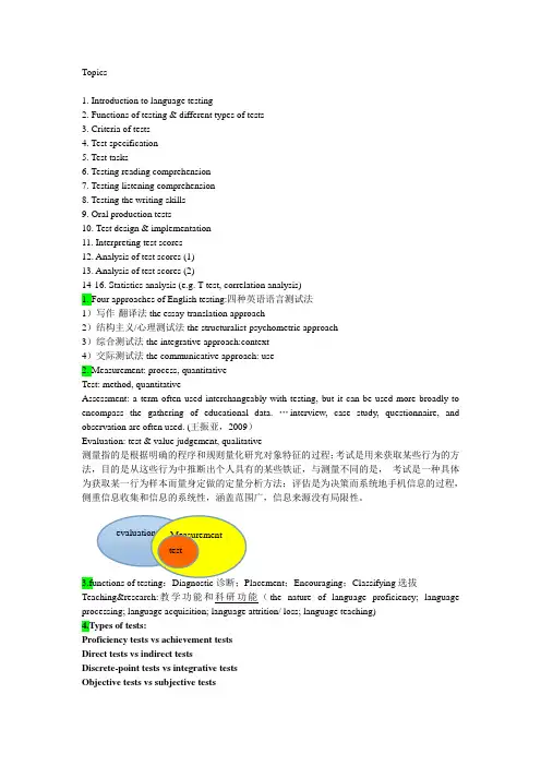
Topics1. Introduction to language testing2. Functions of testing & different types of tests3. Criteria of tests4. Test specification5. Test tasks6. Testing reading comprehension7. Testing listening comprehension8. Testing the writing skills9. Oral production tests10. Test design & implementation11. Interpreting test scores12. Analysis of test scores (1)13. Analysis of test scores (2)14-16. Statistics analysis (e.g. T-test, correlation analysis)1. Four approaches of English testing:四种英语语言测试法1)写作-翻译法the essay-translation approach2)结构主义/心理测试法the structuralist-psychometric approach3)综合测试法the integrative approach:context4)交际测试法the communicative approach: use2. Measurement: process, quantitativeTest: method, quantitativeAssessment: a term often used interchangeably with testing, but it can be used more broadly to encompass the gathering of educational data. …interview, case study, questionnaire, and observation are often used. (王振亚,2009)Evaluation: test & value judgement, qualitative测量指的是根据明确的程序和规则量化研究对象特征的过程;考试是用来获取某些行为的方法,目的是从这些行为中推断出个人具有的某些铁证,与测量不同的是,考试是一种具体为获取某一行为样本而量身定做的定量分析方法;评估是为决策而系统地手机信息的过程,侧重信息收集和信息的系统性,涵盖范围广,信息来源没有局限性。
Accessibility test : 软体适用性测试Ad hoc testing : 随机测试Algorithm analysis : 算法分析Alpha testing : α测试Anomaly : 异常Artifact : 工件Automated Testing : 自动化测试Architecture : 构架Assertion checking : 断言检查Audit : 审计Application under test (AUT) : 所测试的应用程序Baseline : 基线Behaviour : 行为Benchmark : 基准Beta testing : β测试Best practise : 最佳实践Black box testing : 黑盒测试Blocking bug : 阻碍性错误Bottom-up testing : 自底向上测试Branch coverage : 分支覆盖Brute force testing : 强力测试Bug : 错误Bug report : 错误报告Bug tracking system : 错误跟踪系统Build : 工作版本(内部小版本)Boundary values : 边界值Buddy test : 合伙测试Buffer : 缓冲Bug bash : 错误大扫除Build-in : 内置Build Verfication tests(BVTs) : 版本验证测试Cause-effect graph : 因果图Capture/Replay Tool : 捕获/ 回放工具Character Set : 字符集Capability Maturity Model (CMM) : 能力成熟度模型Capability Maturity Model Integration (CMMI) : 能力成熟度模型整合Closeout : 收尾Code coverage : 代码覆盖Code page : 代码页Code rule : 编码规范Code sytle : 编码风格Common sense : 常识Compatibility Testing : 兼容性测试Condition coverage : 条件覆盖Configuration testing : 配置测试Control flow graph : 控制流程图Concurrency user : 并发用户Configuration item : 配置项Core team : 核心小组Customer-focused mindset : 客户为中心的理念体系Crash : 崩溃Criticality analysis : 致命度分析Cyclomatic complexity : 圈复杂度Data Flow Analysis : 数据流分析Decision coverage : 判定覆盖Debug : 调试Defect : 缺陷defect density : 缺陷密度Deployment : 部署Desk checking : 桌前检查Dynamic analysis : 动态分析Entry criteria : 准入条件Equivalence class : 等价类Equivalence partition testing : 等价划分测试Error : 错误Error guessing : 错误猜测Error seeding : 错误播种Exception : 异常/ 例外Exception handlers : 异常处理器Exhaustive testing : 穷尽测试Exploratory testing : 探索性测试Event-driven : 事件驱动Envisioning Phase : 构想阶段Failure : 失效Fault : 故障Field testing : 现场测试Framework : 框架Functional testing : 功能测试Hard-coding : 硬编码Hotfix : 热补丁G11N(Globalization) : 全球化Gap analysis : 差距分析Garbage characters : 乱码字符Glossary : 术语表Glass-box testing : 白箱测试或白盒测试GUI(Graphical User Interface) : 图形用户界面I18N(Internationalization) : 国际化Incremental testing : 渐增测试Installing testing : 安装测试Integration testing : 集成测试Interface : 接口Inspection : 审查Issue : 问题Iteration : 迭代Iterative development : 迭代开发Key concepts : 关键概念Key Process Area : 关键过程区域Keyword driven testing : 关键字驱动测试Kick-off meeting : 启动会议Lag time : 延迟时间Lead time : 前置时间L10N(Localization) : 本地化Localizability testing : 本地化能力测试Localization testing : 本地化测试Load testing : 负载测试Maintenance : 维护Maintainability : 可维护性Master project schedule : 总体项目方案Measurement : 度量Memory leak : 内存泄漏Migration testing : 迁移测试Milestone : 里程碑Mock up : 模型,原型Monkey testing : 跳跃式测试Module testing : 模块测试Negative Testing : 逆向测试, 反向测试, 负面测试N/A(Not applicable) : 不适用的Off-the-shelf software : 套装软件Pair Programming : 成对编程Path coverage : 路径覆盖Peer review : 同行评审Performance : 性能Performance indicator : 性能(绩效)指标Performance testing : 性能测试Pilot : 试验Pilot testing : 引导测试Portability : 可移植性Positive testing : 正向测试Postcondition : 后置条件Pseudo code : 伪代码Precondition : 前提条件Priority : 优先权Prototype : 原型Quality assurance(QA) : 质量保证Quality Control(QC) : 质量控制Recovery testing : 恢复测试Refactoring : 重构Regression testing : 回归测试Release : 发布Release note : 版本说明Reliability : 可靠性Return of Investment( ROI ) : 投资回报率Review : 评审Requirements-based testing : 基于需求的测试Requirements management tool : 需求管理工具Risk assessment : 风险评估Root Cause Analysis(RCA) : 根本原因分析Robustness : 强健性Sanity testing : 健全测试Screen shot : 抓屏、截图Severity : 严重性Security testing : 安全性测试Shipment : 发布Smoke testing : 冒烟测试Software life cycle : 软件生命周期Software development plan(SDP) : 软件开发计划Static testing : 静态测试Simulation : 模拟Simulator : 模拟器SLA(Service level agreement) : 服务级别协议Software development process : 软件开发过程Source code : 源代码Specification : 规格说明书Spiral model : 螺旋模型Statement coverage : 语句覆盖Stepwise refinement : 逐步优化Stress Testing : 压力测试Structural coverage : 结构化覆盖Stub : 桩Synchronization : 同步Syntax testing : 语法分析System analysis : 系统分析System design : 系统设计System integration : 系统集成System Testing : 系统测试Test :测试Testing bed: 测试平台Test case : 测试用例Testing coverage : 测试覆盖Test design : 测试设计Test driver : 测试驱动Testing environment : 测试环境Test infrastructure : 测试基础建设Testing item : 测试项Testing plan : 测试计划Testing procedure : 测试过程Test scenario : 测试场景Test script : 测试脚本Test strategy : 测试策略Test suite : 测试包Test target : 测试目标Testability : 可测试性Testware : 测试工具Top-down testing : 自顶向下测试Thread testing : 线程测试Traceability : 可跟踪性Traceability matrix : 跟踪矩阵Trade-off : 平衡Unit testing : 单元测试User interface(UI) : 用户界面Usability testing : 可用性测试Usage scenario : 使用场景User acceptance Test : 用户验收测试User profile : 用户信息User scenario : 用户场景Version : 版本Virtual user : 虚拟用户Volume testing : 容量测试V&V (Verification & Validation) : 验证& 确认Walkthrough : 走读Waterfall model : 瀑布模型White box testing : 白盒测试Work breakdown structure (WBS) : 任务分解结构Web testing : 网站测试Zero bug bounce (ZBB) : 零错误反弹。

AfPS GS2019:01PAKProduct Safety Commission(AfPS)产品安全委员会(AfPS)GS Specification Testing and assessment of Polycyclic AromaticHydrocarbons(PAHs)多环芳烃(PAHs)的GS规范测试和评价in the awarding of GS Marks-Specification pursuant to Article21(1)No.3of the Product Safety Act(ProdSG)在授予GS标志时-根据产品安全法(ProdSG)的第21(1)条的No.3的规范-AfPS GS2019:01PAKDate of issue:15May2019发行日期:2019年5月15日Management:部门:Federal Institute for Occupational Safety and Health联邦职业安全与健康研究所Table of Contents目录Preliminary observations初步观察1Purpose/Intention目的/意图2Basics基本原理3Procedure过程3.1Risk assessment风险评估3.2Categorisation分类3.3Test and Assessment测试和评估4Transitional regulations/periods过渡性法规/时期4.1GS mark certificates,issued from1July2020onwardsGS标志证书,自2020年7月1日后颁发4.2GS mark certificates,issued before1July2020GS标志证书,在2020年7月1日之前颁发Annex:Test附件:试验Instructions说明1Aim and purpose目标和目的2Procedure过程2.1Brief description简要说明2.2Equipment设备2.3Chemicals and solutions化学品和溶液3Preparation and measurement准备和测试3.1Sample preparation样品制备3.2Measuring procedure测量程序3.3Special characteristcs特殊特征Annex:Gas-chromatographic conditions(informative)附件:气相色谱法条件(提供有用信息的)Testing and assessment of polycyclic aromatic hydrocarbons(PAHs)inthe awarding of GS marks在GS认证中多环芳烃(PAHs)的测试和评估Preliminary observations初步观察On4August2014the Product Safety Commission(AfPS)has determined the requirements of PAH testing in the awarding of the GS mark as specification according to Article21(1)No.3of the Product Safety Act(ProdSG).2014年8月4日,产品安全委员会(AfPS)根据《产品安全法》(ProdSG)第21(1)No.3条,在授予GS标志时确定了PAH测试的要求On15May2019the requirements were reviewed and revised.The GS specification AfPS GS2014:01PAK shall be replaced by this document.The implementation is achieved by means of this PAH document.2019年5月15日,我们对这些要求进行了审查和修订。
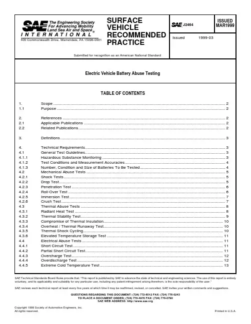
SAE Technical Standards Board Rules provide that: “This report is published by SAE to advance the state of technical and engineering sciences. The use of this report is entirely voluntary, and its applicability and suitability for any particular use, including any patent infringement arising therefrom, is the sole responsibility of the user.”SAE reviews each technical report at least every five years at which time it may be reaffirmed, revised, or cancelled. SAE invites your written comments and suggestions.QUESTIONS REGARDING THIS DOCUMENT: (724) 772-8512 FAX: (724) 776-0243TO PLACE A DOCUMENT ORDER; (724) 776-4970 FAX: (724) 776-0790SAE WEB ADDRESS Table 1Measurement Accuracies (4)Table 2Shock Levels and Durations (5)Table 3Penetration Characteristics (6)Table 4Thermal Heatup Rates and Durations (9)Table 5Number and Type of Devices to be Shorted (12)Table 6Test Conditions Sequence and Required Actions (13)1.Scope—This SAE Recommended Practice is intended as a guide toward standard practice and is subject tochange to keep pace with experience and technical advances. It describes a body of tests which may be used as needed for abuse testing of electric or hybrid electric vehicle batteries to determine the response of such batteries to conditions or events which are beyond their normal operating range. This document is derived from a similar document originally developed by the U.S. Advanced Battery Consortium. (See 2.2.1.)1.1Purpose—These tests are intended to simulate abuse conditions and potential internally initiated failures thatmay be experienced in electrochemical storage systems. These tests were derived from Failure Mode and Effect Analysis, user input and historical abuse testing. The outcome of testing shall be documented for use by potential users of the tested properties. It is not the intent of this procedure to apply acceptance criteria; each application has its own unique requirements and ancillary support systems. Users of these technologies shall make their own determination as to what measures to take to ensure a sound application of said technology.The tests are designed to provide a common framework for various Electrochemical Storage Systems (ECSS) technologies. The primary purpose of the tests is to gather response information to external/internal inputs.Some tests and/or measurements may not be required for some ECSS technologies and designs if it can be demonstrated that the test is not applicable and the measurement will yield no useful information.Note that the device to be tested using any of the procedures in this document is referred to as an Electrochemical Storage System (ECSS); this terminology may refer to an electrochemical cell, module or complete battery system, depending on the particular test.2.References2.1Applicable Publications—The following publications form a part of this specification to the extent specifiedherein. Unless otherwise specified, the latest issue of SAE publications shall apply.2.1.1SAE P UBLICATIONS—Available from SAE, 400 Commonwealth Drive, Warrendale, PA 15096-0001.SAE J1715—Electric Vehicle Terminology2.2Related Publications—The following publications are provided for information purposes only and are not arequired part of this document.2.2.1USABC P UBLICATION—Available from NTIS, 5285 Port Royal Road, Springfield, VA 22161.Electrochemical Storage System Abuse Test Procedure Manual, February 1999 Version 1.0,T. Unkelhaeuser & D. Smallwood, published as Sandia Laboratories report SAND99-04972.2.2AIHA P UBLICATION—Available from American Industrial Hygiene Association, 1997, AIHA Publications,Department #796, Alexandria, VA 22334-0796.Emergency Response Planning Guidelines, Level 23.Definitions3.1Electrochemical Storage Systems (ECSS)—A device for storing electrical energy in a reversibleelectrochemical form for use in mobile or stationary applications. In this document, the ‘device under test’is always referred to as an ECSS whether it consists of a single cell, a multiple cell assembly or module, or a complete battery pack or system.3.2Emergency Response Planning Guidelines, Level 2 (ERPG-2)—ERPG-2 levels are defined as themaximum airborne concentration below which it is believed that nearly all individuals could be exposed for up to 1 h without experiencing or developing irreversible or other serious health effects or symptoms which could impair an individual’s ability to take protective action. This guideline is taken from the American Industrial Hygiene Association. Other world standards with like intent may be substituted, because use of these concentration levels is for comparison purposes only.3.3Fully Charged—100% State of Charge. The state of an ECSS after a full charge cycle as specified by theECSS manufacturer. For purposes of this document, an ECSS is considered fully charged up to 4 h after the completion of the charge cycle provided that the state of charge is not expected to fall below 95%.4.Technical Requirements4.1General Test Guidelines—Subjecting batteries to conditions outside their intended operating rangenecessarily involves some risk of unintended failures. The responsible testing organization should consult the battery manufacturer for information regarding the possible consequences of such failures, including the potential release of hazardous substances, so that appropriate precautions can be taken for the safety of testing personnel.4.1.1H AZARDOUS S UBSTANCE M ONITORING—The release of hazardous substances should be measured andreferenced to the ERPG-2 levels. ERPG-2 refers to the Emergency Response Planning Guidelines, Level 2, from the American Industrial Hygiene Association. ERPG-2 levels are defined as the maximum airborne concentration below which it is believed that nearly all individuals could be exposed for up to 1 h without experiencing or developing irreversible or other serious health effects or symptoms which could impair an individual’s ability to take protective action. Use of these levels as a reference is done for comparison purposes only.Tests which require hazardous substance monitoring should be conducted in a closed volume of appropriate size to accommodate the test article and provide adequate air space to ensure a “normal”atmosphere. Any released gas concentration in that volume shall be normalized to a 1 m3 volume for quantitative analysis. If it is not practical to perform any test in a closed volume due to test article size, it is permissible to perform the test out of doors provided that wind speed is 3 mph or less. A minimum of three hazardous substances monitors, approximately equally spaced around the unit, should be placed as close as reasonable to the test and moved as close as practical to the ECSS after the test. (The rollover test is an exception to this.) Hazardous substance monitors shall be selected with respect to anticipated release products;manufacturer’s input will generally be required to determine this. If it is reasonable to expect that a specific technology will not vent during a particular test, or that gas collected will not be significantly different from that previously collected, gas collection and analysis are not required. The time resolution of such sampling is not specified because of the wide variability in test dynamics and release amounts/rates expected.The flammability of any expelled materials must be determined. The lower limit of flammability in air is used for flammable gases and liquids. For example, the lower limit of flammability in air for H2 is 4%.For substances not considered hazardous, the EPA reportable release limits are used as a reference for comparison purposes only. A release means any spilling, leaking, pumping, pouring, emitting, emptying, discharging, injecting, escaping, leaching, dumping, or disposing into the environment.4.1.2T EST C ONDITIONS AND M EASUREMENT A CCURACIES—All ECSS test articles shall be in a fully charged state, atnormal operating temperature with any cooling media in place and thermal control systems running unless specifically stated otherwise. All test articles will be observed for a time period of at least 1 h or until such time that said test article is judged safe to handle after each test unless specifically stated otherwise.Except where specifically stated otherwise (e.g., temperature abuse tests), the ambient temperature for any tests defined in this document shall be 25 °C ± 3 °C, and the ECSS environment shall be stabilized at this temperature prior to the start of testing.Measured data shall be acquired at rates and with accuracies adequate to assure that the usefulness of the test data is not compromised. In the absence of more specific requirements by the test sponsor, the measurement accuracies in Table 1 shall be considered acceptable. Because of the wide variety of test dynamics, it is not possible to specify absolute data rates. However, the required data for a particular test shall be acquired at a rate such that errors due to test dynamics will not exceed the required measurement accuracies. For example, if the required accuracy for a given test is 10 °C, the temperature shall be measured sufficiently often that measurement delays will not contribute more than 10 °C error to the resulting data during the important parts of the test.TABLE 1—MEASUREMENT ACCURACIESParameter AccuracyTemperature±2 °C ± 5% of readingVoltage, Current, Resistance1% of readingVibration, Deformation4% of readingHazardous Substance Concentration10% of reading4.1.3N UMBER, C ONDITION, AND S IZE OF B ATTERIES TO BE T ESTED—Initial testing will probably be with a new ECSS,as systems or subsystems which have seen part of their useful life will not be available. Future efforts may include an ECSS well into, or near the end, of its useful life. Permutations of state of charge, system age, and temperature should be implemented at the test sponsor’s or manufacturer’s discretion based on the most susceptible condition of the technology. Note that information will generally be needed from the ECSS manufacturer to determine what types of hazardous substances (if any) may be expected to be released during a given test.Abuse testing is to be performed to characterize the ECSS response to undesirable conditions or environments associated with carelessness, poorly informed or trained users or mechanics, failure of specific ECSS control and support hardware, or transportation/handling incident or other accidents involving the ECSS. Some of these conditions can reasonably be expected to be encountered infrequently, but nevertheless represent conditions for which the ECSS was not designed or intended for use. Some of the tests are not applicable to all candidate ECSS technologies. Many of these tests may result in intentional destruction of the device under test. The required number of batteries to be subjected to testing will depend on actual performance (e.g., a single ECSS of some types may be capable of surviving all but the crush test, whereas for other technologies, as many as 3 to 4 batteries may be required). It is acceptable to use a new ECSS for each test. However, in many cases, it may be economically or technically desirable to subject a single device to multiple tests, either to reduce the number of test articles required or to study the interaction of multiple events (e.g., mechanical shocks followed by penetration, immersion, or high temperatures.)In general these tests should be conducted at the lowest level of assembly for which meaningful data can be gathered, i.e., cell, multi-cell module, or complete battery pack or system. The recommended lowest level of assembly to be used for each test is indicated on the title line for each test. Tests are grouped into three categories: mechanical, thermal, and electrical abuse. Some tests have been arbitrarily classified as they contain more than one of these elements.4.2Mechanical Abuse Tests—The mounting and support of the ECSS shall be as similar as possible to themanufacturers recommended EV installation requirements for mechanical shock and vibration tests. If the support structure has any resonance below 50 Hz, the input will be determined by the average of the acceleration at each of the major support points.4.2.1S HOCK T ESTS (M ODULE L EVEL OR A BOVE )4.2.1.1Test Description—Subject the ECSS to shock events at one or more defined shock levels. The low level shock is a robustness test which an ECSS will generally survive without damage. The mid-level shocks are more severe and the ECSS may be inoperable after the test. Shock levels and durations are defined in Table 2. Each shock level is specified in terms of a velocity change and a corresponding maximum duration. (Shock duration is defined as the time between 10% and 90% of peak value.) Achieving this velocity change over this maximum duration is the goal of the test; however, the characteristics of the acceleration (deceleration) pulse are limited by the test equipment used.The maximum duration places lower limits on the peak acceleration which must be seen during the test.For example, for the low level test, the lowest possible acceleration meeting the requirements would be achieved if the acceleration was an ideal square wave of about 12.5 g. The minimum peak acceleration in Table 2 is specified at about twice this level, recognizing that an ideal square wave cannot be achieved in a real test. It is expected that a simple pulse shape (such as a half-sine) will be used for the test, but the pulse shape is not specified to allow as much flexibility as possible in the testing laboratory. Advanced techniques which more accurately simulate actual deceleration time histories are not excluded. It is generally in the interest of the ECSS manufacturer to keep the pulse duration as long as possible while meeting the specification. However, if the ECSS is robust, it may be desirable to increase the peak acceleration and/or reduce the duration if this reduces test complexity and cost.4.2.1.2Measured Data—The following data shall be collected as part of this test:a.Air concentrations of hazardous gases, or concentrations of hazardous liquids or solids, expected to be released shall be collected and analyzed as a function of time. b.Acceleration input to ECSS case, with a minimum of 2 kHz bandwidth.c.Measurements of the ECSS deformation after the test.d.Temperature of the ECSS case as a function of time.e.Potential and resistance of the ECSS case with respect to the positive and negative terminals before and after the test.f.Still photographs, of the test setup, and the ECSS before and after the test.g.High-speed motion pictures of test, 400 frames/s.4.2.2D ROP T EST (P ACK L EVEL O NLY )4.2.2.1Test Description—Drop the ECSS (free drop) from 10 m (33 ft) onto a centrally located, cylindrical object(telephone pole or equivalent) having a radius of 150mm. The ECSS shall impact across the radius (not the end) of the cylindrical object. A horizontal impact with an equivalent velocity change is acceptable.The ECSS should be observed for a minimum of 1 h after the test. Note that this test may not be suitable for use with batteries whose enclosures are not independent structural components.TABLE 2—SHOCK LEVELS AND DURATIONSLevelVelocity (m/s)Max Duration (ms)Minimum Acceleration Acceptable Pulse Form Low6.7 5520 g for 11 ms 25 g 30 ms halfsine Mid-111.1 6530 g for 16 ms 35 g 51 ms halfsine Mid-213.3 11020 g for 22 ms 25 g for 60 ms halfsine4.2.2.2Measured Data—The following data shall be collected as part of this test:a.Air concentrations of hazardous gases, or concentrations of hazardous liquids or solids, expected tobe released shall be collected and analyzed as a function of time.b.Acceleration input to ECSS case, with a minimum of 10 kHz bandwidth.c.Measurements of the ECSS deformation after the test.d.Temperature of the ECSS case as a function of time.e.Potential and resistance of the ECSS case with respect to the positive and negative terminals beforeand after the test.f.Still photographs, of the test setup, and the ECSS before and after the test.g.High-speed motion pictures of test, 400 frames/s.4.2.3P ENETRATION T EST (C ELL L EVEL OR A BOVE)4.2.3.1Test Description—Penetrate the ECSS with a mild steel (conductive) pointed rod. The rate of penetrationshall be 25 cm/s or less. The diameter of the rod and the depth of penetration can be found in Table 3.The orientation of the penetration shall be perpendicular to the electrode plates.TABLE 3—PENETRATION CHARACTERISTICSSize of Test Object Diameter of Rod Minimum Depth of PenetrationCell 3 mm Through cellModule/Pack20 mm Through 3 cells or 100 mm4.2.3.2Measured Data—The following data shall be collected as part of this test:a.Air concentrations of hazardous gases, or concentrations of hazardous liquids or solids, expected tobe released shall be collected and analyzed as a function of time.b.Measurements of the ECSS deformation after the test.c.Temperature of the ECSS case as a function of time.d.Potential and resistance of the ECSS case with respect to the positive and negative terminals beforeand after the test.e.Still photographs, of the test setup, and the ECSS before and after the test.f.High-speed motion pictures of test, 400 frames/s.g.The ECSS should be observed for a minimum of 1 h after the test with the rod remaining in place.4.2.4R OLL-OVER T EST (M ODULE L EVEL OR A BOVE)4.2.4.1Test Description—Rotate the ECSS one complete revolution in 1 min in a continuous slow roll fashion, andobserve whether any material leaks from the ECSS. Then rotate the ECSS in 90 increments for one full revolution. Observe the ECSS for 1 h at each position and for a minimum of 1 h after the test.4.2.4.2Measured Data—The following data shall be collected as part of this test:a.Air concentrations of hazardous gases, or concentrations of hazardous liquids or solids, expected tobe released shall be collected and analyzed as a function of time.b.Temperature of the ECSS case as a function of time.c.Potential and resistance of the ECSS case with respect to the positive and negative terminals beforeand after the test.d.Still photographs of the test setup and the ECSS before the test and at each rotational position.e.Analysis of any substance that may leak from the battery, particularly its flammability.4.2.5I MMERSION T EST (M ODULE L EVEL OR A BOVE)4.2.5.1Test Description—With the ECSS in its normal operating orientation, immerse the ECSS in salt water(nominal composition of seawater) for a minimum of 2 h or until any visible reactions have stopped. The water depth must be enough to completely submerge the ECSS.4.2.5.2Measured Data—The following data shall be collected as part of this test:a.Temperature of the ECSS case as a function of time.b.Air concentrations of extremely hazardous substances as a function of time, measured above theECSS with one or more hazardous substance monitors.c.Potential and resistance of the ECSS case with respect to the positive and negative terminals beforeand after the test.d.Still photographs, of the test setup, and the ECSS before and after the test. The entire test shall bevideo taped.e.If there are clearly visible releases of substances from the ECSS in the water, samples of these shouldbe analyzed for toxicity.4.2.6C RUSH T EST (C ELL L EVEL OR A BOVE)4.2.6.1Test Description—The ECSS shall be crushed between a fixed surface and a textured platen. The platenshall have semi-cylindrical intruders that have a 75 mm radius and placed 30 mm from one another across the face of the platen. Figure 1 illustrates the approximate shape of the platen.FIGURE 1—CRUSH TEST PLATENThe ECSS shall be at nominal operating temperature. It shall have all integrated control and interconnect circuitry (if provided--may not be applicable at the cell level) in place and operating. An ECSS is to be crushed once in each of the three axes (using a different ECSS for each crush), with the irregular surface of the platen at the most vulnerable location. For each unit, crush to 85% of the initial dimension and hold for 5 min. After the hold period, continue the crush to 50% of the initial dimension. The crush force may be limited to a maximum of 1000 times the weight of the ECSS. If the test is performed outside, the wind speed should be <3 mph. A minimum of three hazardous substances monitors, approximately equally spaced around the unit, should be placed as close as reasonable to the test and moved as close as practical to the ECSS after the test.4.2.6.2Measured Data—The following data shall be collected as part of this test:a.Air concentrations of hazardous gases, or concentrations of hazardous liquids or solids, expected tobe released shall be collected and analyzed as a function of time.b.Internal and external ECSS temperature.c.ECSS voltage, as appropriate.d.Video and still photographs of the ECSS before, during, and after the test.4.3Thermal Abuse Tests4.3.1R ADIANT H EAT T EST(C ELL L EVEL OR A BOVE)4.3.1.1Test Description—With the ECSS at 80% SOC, expose it to high temperature for 10 min by placing itinside a radiant heating fixture. The fixture shall be programmed to reproduce the temperature experienced in a fuel fire (890 °C nominal). The programmed temperature shall be achieved within 90 s and held for a period of 10 min or until another condition occurs which would prevent the completion of the tests. The ECSS should be in its normal operation orientation and will not be insulated or protected unless this is the standard configuration for the test article. If the ECSS ignites, it may be extinguished with a method appropriate for the technology.The test fixture for this test is a cylindrical metallic fixture whose inside is coated such that it will radiate approximately like a black body. The exterior is radiated with radiant heat. The test temperature is controlled by thermocouples mounted on the interior surface of the fixture, with the device under test placed in the center of the fixture such that it does not contact the fixture walls. A sketch of such a test fixture is shown in Figure 2. If such a fixture is not available, this test can be conducted using some other means (e.g., a tube furnace and conveyer mechanism) that would expose the ECSS to non-contact heat from a cylindrical radiating surface at 890 °C, where the surface temperature which the ECSS sees increases from ambient to the test value within 90 s.FIGURE 2—TEST FIXTURE4.3.1.2Measured Data—The following data shall be collected as part of this test:a.Air concentrations of hazardous gases, or concentrations of hazardous liquids or solids, expected tobe released shall be collected and analyzed as a function of time.b.Temperature of the ECSS case as a function of time.c.Potential and resistance of the ECSS case with respect to the positive and negative terminals beforeand after the test.d.Video and still photographs, of the test setup, and the ECSS before, during and after the test.4.3.2T HERMAL S TABILITY T EST (C ELL L EVEL OR A BOVE)4.3.2.1Test Description—The ECSS shall be in a fully charged state and at normal operating temperature at thebeginning of the test. If the temperature at which a major exothermic reaction occurs is known, the test may begin at 10% less than this temperature to save time. Place the ECSS in a device or chamber capable of heating the ECSS to 200 °C above its operating temperature. For cells, it is desirable for this device to be capable of maintaining a near adiabatic state (Accelerated Rate Calorimeter (ARC) apparatus or similar). Increase the temperature in increments as shown in Table 4, and hold at each temperature step for the minimum time shown in Table 4, or until any self heating is detected. If self heating is detected, it is desirable for the chamber temperature to track the ECSS temperature until it stabilizes; this will minimize the test duration. The temperature is then increased to the next increment and continued as described previously until either (a) additional self heating is detected, (b) the temperature reaches 200 °C above the operating temperature of the ECSS or (c) a catastrophic event occurs (e.g., venting or major damage to the ECSS.)If the ECSS experiences a thermal runaway, the test should be repeated to further define the exact thermal stability limit. Increase the temperature at a constant rate to the first step below the event temperature. The temperature will then be increased in 2 °C increments and held for a minimum of 1 h until the event is repeated and the thermal stability limit is defined.This test should be repeated with cells that have been overcharged to 150% of the rated capacity (using the conditions of Procedure 4.4.3) and cells that have been cycled to 50% and 100% of nominal life. The overcharge may be limited to a value that will not physically damage the cell (e.g., by venting or rupture) prior to conduct of the thermal stability test.4.3.2.2Measured Data—The following data shall be collected as part of this test:a.Temperature(s) at which venting occursb.Temperature(s) of any smoke generation or other major eventsc.Cell temperature profile with respect to timed.Oven/chamber temperature profile with respect to timeTABLE 4—THERMAL HEATUP RATES AND DURATIONSECSS Assembly Level Heatup Rate Increment(°C)Hold Time at EachTemperature Step(min)Cell530 Module or higher (exothermtemperature known)10120Module or higher (exothermtemperature unknown)201204.3.3C OMPROMISE OF T HERMAL I NSULATION(M ODULE LEVEL OR ABOVE)4.3.3.1Test Description—With the ECSS at nominal operating temperature and fully charged, compromise theinsulation system integrity or other applicable device and allow the case external temperature to reach steady state.4.3.3.2Measured Data—The following data shall be collected as part of this test:a.Internal and external temperature distribution4.3.4O VERHEAT/T HERMAL R UNAWAY T EST (M ODULE L EVEL OR A BOVE)4.3.4.1Test Description—With the ECSS at nominal operating temperature, fully charged, contained in a closedvolume, and all thermal controls (primary and secondary) disabled, perform C/1 cycling utilizing the manufacturers defined charge algorithm for 20 cycles with no rest period between charge or discharge.Perform three baseline C/3 cycles after the test with thermal control active to determine the effects on the ECSS.4.3.4.2Measured Data—The following data shall be collected as part of this test:a.Note any venting of the ECSSb.Internal (if possible) and external ECSS temperaturec.Voltage and resistance of the ECSS case with respect to the positive and negative terminals beforeand after the testd.Still photographs of the ECSS before, during, and after the teste.ECSS voltage and current as a function of time4.3.5T HERMAL S HOCK C YCLING (C ELL L EVEL OR A BOVE)4.3.5.1Test Description—With the ECSS at 50% State of Charge, contained in a closed volume, and all thermalcontrols (primary and secondary) disabled, thermally cycle the ECSS with ambient air cycling between 80°C to –40 °C. The time to reach each temperature extreme shall be 15 min or less; this test may be performed either through the use of a fast-response chamber, or by moving test articles between two chambers at the two test temperatures. The ECSS shall remain at each extreme for a minimum of 1 h at the cell level, 6 h at the module level, or as required to reach uniform temperature at the pack level. A total of five cycles shall be performed. After thermal cycling, inspect the ECSS for any damage, paying special attention to any seals that may exist. Also, determine whether control circuitry, if any, is operational.Perform three C/3 discharge cycles at 25 °C ambient air temperature (using the manufacturers recharge algorithm) to determine immediate effects of the thermal cycling.4.3.5.2Measured Data—The following data shall be collected as part of this test:a.ECSS voltage during thermal cyclingb.Note any venting of the ECSSc.Voltage and resistance of the ECSS case with respect to the positive and negative terminals beforeand after the testd.Still photographs of the ECSS before and after the test。


第33卷第4期江西师范大学学报(自然科学版)Vol .33No .42009年8月 JOURNAL OF J I A NGX INOR MAL UN I V ERSI TY (NAT URAL SC I E NCE ) Aug .2009收稿日期:2009204201基金项目:国家“863”计划预研项目.作者简介:韩采芹(19822),女,四川苍溪人,硕士研究生,主要从事数字CCD 相机光电特性研究.文章编号:100025862(2009)0420398203不同光照条件下数字CC D 相机响应不均匀性研究韩采芹1, 陶跃珍1, 李 华2, 沈忙作2(1.四川理工学院机械工程学院,四川自贡 643000;2.中国科学院光电技术研究所,四川成都 610209)摘要:从理论上分析了数字CCD 相机光电响应不均匀性的原因,通过建立数字CCD 相机响应不均匀性测试系统和三维模型,推导出了数字CCD 相机响应不均匀性的计算公式,对数字CC D 相机的响应不均匀性进行测量与分析,给出了测试系统的结构框图和部分测试结果.关键词:CC D 相机;响应不均匀性;32D 模型中图分类号:T N 206 文献标识码:A在新型光电传感器中,电荷耦合器件(CCD )[1]由于本身具有优良的光电和机械特性而在电视摄像、现代办公设备、机器人视觉、目标跟踪和工业检测等领域得到了广泛应用.但是在实际应用中,特别是在高精度的测量中,CCD 各像元光电特性的不均匀会给测量结果带来较大的误差.为了提高测量精度,必须对CCD 器件本身的响应不均匀性进行测量[223],以便在测量过程中能对检测结果进行校正.CCD 是一种大规模半导体集体器件,生产工艺相当复杂,在生产制造过程中,难免产生掺杂浓度的不均匀、淀积厚度的差异,以及光刻误差.一旦制成成品,这种先天性的缺陷就无法改变,从而引入了固定模式的噪声,表现为暗电流及响应率的不均匀性[4210].1 响应不均匀性分析图1 T 帧图像输出信号在CCD 成像系统中,CCD 各光敏单元对相同照度产生的不同输出信号称为CCD 响应的不均匀性.该参数表征了CCD 各像元响应度的不一致性.它不仅与器件的制造工艺有关,而且还与入射光的波长和衬底材料性能有关.由于近红外光在硅中穿透能力较强,所以用近红外光所测得的还包含了衬底材料性能对不均匀性的影响.由于响应不均匀性PRNU 的随机性很大,没有一定的规律,而且因器件而异,所以,对于某些弱信号检测或高精度应用而言,必须进行实际测量,然后加以补偿才能达到均匀性要求.一般说来,CCD 像元数越多,不均匀性越严重.采集CCD 相机输出端数据,然后对采集的数据按照三维模型进行处理.设在一定均匀照明下,连续采集T 帧具有X ×Y 个像素的图像.每一幅二维图像具有Y 列X 行,共X ×Y 个信号值,T 帧图像共有X ×Y ×T 个具有三维坐标的输出信号值,如图1所示.为区别于三维立体图,把这种图像称为三维结构图像.任一点的坐标为(x,y,t ),x =1,2,…,X;y =1,2,…,Y ;t =1,2,…,T;任一点的信号值记为S (x,y,t ).CCD 相机响应不均匀性被定义为在50%饱和曝光量条件下,各像元输出信号的标准差与平均值之比,符号为PRNU ,即PRUN =1珔S 1X Y ∑X x =1∑Y y =1(珔S (x,y )-珔S )2,(1)其中:珔S (x,y )=1T ∑T t =1S (x,y,t )为第(x,y )光敏元的时间序列平均值;珔S =1X YT ∑X x =1∑Y y =1∑Tt =1S (x,y,t )为所有像素的灰度平均值.运用上述公式可以得到某照度下图像输出信号的时间序列平均值珔S (x,y )和响应不均匀性PRNU.图2 CCD 相机响应不均匀性测量系统2 测量系统图2为CCD 相机相应不均匀性测量系统原理框图.光源由25个发光二极管(LE D )组成,用来提供均匀光场,测量得到光照度的不均匀性为0.1%,时间稳定性为0.74%.通过改变稳压电源的电压,从而在CCD 相机光敏面处获得变化的光照度.CCD 相机和光照度计放在导轨上,测量时,先将光照度计的探头放置在光源所对应的中心处,测出光照度,移走光照度计,在不改变光照度的情况下,再将待测CCD 相机的光敏面放置在相同位置处.CCD 相机输出的信号通过图像采集卡转换成数字信号后送入计算机,从而获得CCD 相机在该照度下各光敏元实际测得的灰度值.3 响应不均匀性测量与分析运用上述测试装置测试了在不同光照条件下Kodak 相机、Dalsa 相机和Coolsnap 相机的响应不均匀性.首先使CCD 相机无任何光输入,连续采集100帧图像;然后改变入射到CCD 相机的光照度,连续采集100帧图像.采集完后根据(1)式计算CCD 相机的时间序列平均值珔S (x,y )和响应不均匀性,结果如图3所示.(a )Kodak 相机(b )Dalsa相机(c ) Coolsnap 相机图3 响应不均匀性三维结构图993第4期韩采芹,等:不同光照条件下数字CCD 相机响应不均匀性研究004江西师范大学学报(自然科学版)2009年图3的z轴表示所在像点时间序列平均值,而且图中每一点代表此点在所在的行列坐标点上,CCD相机对应位置所具有时间序列平均值的情况.(a)是Kodak相机在33.281lx・m s曝光量下时间序列平均值三维分布,时间序列平均值在空间水平方向呈左低右高分布,并且各像点的时间序列平均值相差很大,是由于Kodak相机是行间转移结构;图3(b)是Dalsa相机在12.070lx・m s曝光量下时间序列平均值三维分布,时间序列平均值在空间水平方向呈左高右低分布,并且存在多处明显小于其余各点,这些点为Dalsa相机光敏面上的奇异点,Dalsa相机是由两块光敏面组成的帧转移结构;图3(c)是Coolsnap相机在66.910lx・m s曝光量下时间序列平均值三维分布,时间序列平均值在空间水平方向呈四周的信号强于其它地方,并且存在3处明显低于其余各点,这3点就为Coolsnap相机光敏面上的奇异点.这说明,在一定曝光量下,面阵CCD相机每个像敏单元的时间序列平均值是不相同的,即CCD相机的响应是不完全均匀的.由公式(1)计算得到,在图3对应的曝光量下,Kodak相机的响应不均匀性为4.36%,Dalsa相机的响应不均匀性为2.53%,Coolsnap相机的响应不均匀性为0.73%.这表明:Coolsnap相机的响应不均匀性最好.由于Coolsnap相机采用了致冷技术,响应不均匀性得到一定的改善.4 结论此方法测试是采用发光二极管产生均匀光场,具有很好的均匀性.在实验室内,根据成像系统响应不均匀性理论,对CCD相机器件进行评价,得到较为满意的结果,而且具有很好的重复性.这种方法不但能评价科学级CCD相机噪声,对普通CCD相机也完全适用.本工作对进一步研究CCD相机相应不均匀性具有实际意义.参考文献:[1]陈迎娟,张之江,张智强.CCD像素相应不均匀性的校正方法[J].光学精密工程,2004,12(2):2162220.[2]张鑫,林家明,张哲,等.大视场CC D成像系统像面均匀性测试技术研究[J].光学技术,2005,31(6):8462848.[3]李恩德,段海峰,杨泽平,等.电荷耦合器件光电响应特性标定研究[J].强激光与粒子束,2006,18(2):2272229.[4]李同保,万光毅,张淑智,等.光探测器响应度均匀性的自动测量装置[J].光电工程,1993,20(3):34240.[5]李永远,谢小平.CCD输出信号处理[J].应用光学,1997,18(1):21223.[6]Ja mes R.Janesick.Present and future CCD’s f or UV and X2tay scientifie measure ments[J].I EEE Trans,1985,32(1):4092416.[8]Patric M,Eppers on.Electr o2op tical characterizati on of tektr onix TK512M2011charge2coup led devices[J].Op t Engng,1987,26(8):7152723.[9]O rbock J D.Charge transfer efficiency measure ments at l ow signal levels on STI S2S OHO TK1024CCD’s[J].SP I E,1990,12423:1052112.[10]张保民.成像系统分析导论[M].北京:国防工业出版社,1992.Research for Respon se Nonun i form ity of D i g it a l CCD Cam erai n D i fferen t I n ten sity of Illu m i n a ti onHAN Cai2qin1, T AO Yue2zhen1, L I Hua2, SHEN Mang2zuo2(1.School of Mechanical Engineering,Sichuan University of Science and Engineering,Zigong Sichuan643000,China;2.The I nstitute of Op itics and Electr onics,the Chinese Acade my of Sciences,Chengdu610209,China)Abstract:I n this paper,the causes f or digital CCD ca mera’s op tics2electr on res ponse nonunif or m ity is theoretically analyzed.Thr ough establishing digital CCD ca mera res ponse nonunif or m ity testing syste m and32D model,this pa2 per deduces the calculati on f or mula of the res ponse nonunif or m ity,res ponse nonunif or m ity of digital CCD camera was measured and analyzed.A t the sa me ti m e,the fra me work of the testing syste m and a part of the tested results was given.Key words:CCD ca mera;res ponse nonunif or m ity;32D model(责任编辑:冉小晓)。

iec29119软件测试国际标准IEC 29119: Software Testing International StandardIntroduction:Software testing plays a crucial role in ensuring that software products meet the necessary quality standards before they are released to the market. To ensure uniformity and consistency in software testing procedures, the International Electrotechnical Commission (IEC) has developed the IEC 29119: Software Testing International Standard. This standard provides a comprehensive framework for software testing processes, techniques, documentation, and terminology. In this article, we will explore the key aspects of the IEC 29119 standard and its significance in the software testing industry.1. Overview of IEC 29119:The IEC 29119 standard consists of five parts, each focusing on different aspects of software testing. These parts include:- Part 1: Concepts and Definitions- Part 2: Test Processes- Part 3: Test Documentation- Part 4: Test Techniques- Part 5: Keyword-Driven Testing2. Part 1: Concepts and Definitions:Part 1 of the IEC 29119 standard provides a clear understanding of the fundamental concepts and definitions related to software testing. It establishes a common vocabulary that ensures uniformity in communication among testers and stakeholders. This section covers key terms such as test case, test plan, test execution, and test management, among others.3. Part 2: Test Processes:Part 2 focuses on the test processes involved in software testing. It defines a systematic approach to software testing, covering various stages such as test planning, test analysis, test design, and test implementation. This part emphasizes the importance of traceability, risk-based testing, and the need for continuous improvement in the testing process.4. Part 3: Test Documentation:Part 3 provides guidelines for the creation and maintenance of test documentation. It emphasizes the importance of clear and concise documentation to ensure effective test planning, test execution, and test reporting. This section covers various documentation types, including test plans, test cases, test scripts, and test logs.5. Part 4: Test Techniques:Part 4 focuses on different test techniques that can be employed during software testing. It provides detailed guidance on various techniques such as black-box testing, white-box testing, boundary value analysis, equivalence partitioning, and decision table testing. This section aims to assist testers in selecting appropriate techniques based on their specific testing objectives and requirements.6. Part 5: Keyword-Driven Testing:Part 5 introduces the concept of keyword-driven testing, which is an approach that allows testers to create reusable test scripts using keywords and associated test data. This section provides guidelines on how to develop and maintain keyword-driven test scripts, enabling efficient and effective test automation.7. Benefits of IEC 29119:The implementation of IEC 29119 brings several benefits to the software testing industry. Some of the key benefits include:- Improved consistency: The standard ensures consistent testing processes, techniques, and documentation, leading to improved communication and collaboration among testing teams.- Increased reliability: By following the standard's guidelines, organizations can enhance the reliability of their software products, resulting in reduced defects and improved customer satisfaction.- Industry-wide recognition: Adhering to the IEC 29119 standard demonstrates an organization's commitment to quality and professionalism in software testing, enhancing its reputation in the industry.- Facilitates international cooperation: Since the standard is internationally recognized, it promotes cooperation and mutual understanding among organizations from different countries, leading to the exchange of best practices and continuous improvement in software testing processes.8. Criticisms and Controversies:Despite its many benefits, the IEC 29119 standard has faced criticism and controversies within the software testing community. Some critics argue that the standard is too prescriptive and limits innovation and flexibility in testing approaches. Additionally, there have been debates about the standard's relevance in agile and DevOps environments, where iterative and continuous testing methodologies are prevalent.Conclusion:The IEC 29119: Software Testing International Standard serves as a comprehensive guideline for organizations in the field of software testing. By establishing uniformity in processes, techniques, and documentation, the standard aims to enhance the quality and reliability of software products. While it has faced criticisms, the standard's widespread recognition and adoption within the industry underline its significance in ensuring consistent and effective software testing practices.。

Reference number ISO 3452-1:2008(E)© ISO 2008INTERNATIONAL STANDARD ISO 3452-1First edition 2008-09-01Non-destructive testing — Penetrant testing —Part 1:General principlesEssais non destructifs — Examen par ressuage — Partie 1: Principes générauxISO 3452-1:2008(E)PDF disclaimerThis PDF file may contain embedded typefaces. In accordance with Adobe's licensing policy, this file may be printed or viewed but shall not be edited unless the typefaces which are embedded are licensed to and installed on the computer performing the editing. In downloading this file, parties accept therein the responsibility of not infringing Adobe's licensing policy. The ISO Central Secretariat accepts no liability in this area.Adobe is a trademark of Adobe Systems Incorporated.Details of the software products used to create this PDF file can be found in the General Info relative to the file; the PDF-creation parameters were optimized for printing. Every care has been taken to ensure that the file is suitable for use by ISO member bodies. In the unlikely event that a problem relating to it is found, please inform the Central Secretariat at the address given below.COPYRIGHT PROTECTED DOCUMENT© ISO 2008All rights reserved. Unless otherwise specified, no part of this publication may be reproduced or utilized in any form or by any means, electronic or mechanical, including photocopying and microfilm, without permission in writing from either ISO at the address below or ISO's member body in the country of the requester. ISO copyright officeCase postale 56 • CH-1211 Geneva 20 Tel. + 41 22 749 01 11 Fax + 41 22 749 09 47 E-mail copyright@ Web Published in Switzerlandii © ISO 2008 – All rights reservedISO 3452-1:2008(E)ForewordISO (the International Organization for Standardization) is a worldwide federation of national standards bodies (ISO member bodies). The work of preparing International Standards is normally carried out through ISO technical committees. Each member body interested in a subject for which a technical committee has been established has the right to be represented on that committee. International organizations, governmental and non-governmental, in liaison with ISO, also take part in the work. ISO collaborates closely with the International Electrotechnical Commission (IEC) on all matters of electrotechnical standardization. International Standards are drafted in accordance with the rules given in the ISO/IEC Directives, Part 2.The main task of technical committees is to prepare International Standards. Draft International Standards adopted by the technical committees are circulated to the member bodies for voting. Publication as an International Standard requires approval by at least 75 % of the member bodies casting a vote.Attention is drawn to the possibility that some of the elements of this document may be the subject of patent rights. ISO shall not be held responsible for identifying any or all such patent rights.ISO 3452-1 was prepared by the European Committee for Standardization (as EN 571-1:1997) and was adopted, under a special "fast-track" procedure, by Technical Committee ISO/TC 135, Non-destructive testing, Subcommittee SC 2, Surface methods, in parallel with its approval by the ISO member bodies.ISO 3452-1 cancels and replaces ISO 3452:1984 which has been technically revised.Throughout the text of this document, read "this European Standard" and "this standard" to mean "this International Standard".ISO 3452 consists of the following parts, under the general title Non-destructive testing — Penetrant testing:⎯Part 1: General principles⎯Part 2: Testing of penetrant materials⎯Part 3: Reference test blocks⎯Part 4: Equipment⎯Part 5: Penetrant testing at temperatures higher than 50 °C⎯Part 6: Penetrant testing at temperatures lower than 10 °CAnnex ZZ provides a list of corresponding International and European Standards for which equivalents are not given in the text.© ISO 2008 – All rights reserved iiiISO 3452-1:2008(E)iv © ISO 2008 – All rights reservedPage 2EN 571-1:1997ForewordThis European Standard has been prepared by Technical Committee CEN/TC 138,Non-destructive testing,the secretariat of which is held by AFNOR.This European Standard shall be given the national standard,either by publication of text or by endorsement,at the latest by conflicting national standards shall be the latest by July 1997.In the framework of its scope,Technical Committee CEN/TC 138entrusted CEN/TC 138/WG 4,Liquidpenetrant testing,to prepare this European Standard.EN 571comprises a series of European Standards on penetrant testing which is made of the following:EN 571-1Non-destructive testing ÐPenetrant testing ÐPart 1:General principlesEN 571-2Non-destructive testing ÐPenetrant testing ÐPart 2:Testing of penetrant materials EN 571-3Non-destructive testing ÐPenetrant testing ÐPart 3:Reference test blocksThis European Standard has been prepared under a mandate given to CEN by the European Commission and the European Free Trade Association,and supports essential requirements of EU Directive(s).According to the CEN/CENELEC Internal Regulations,the national standards organizations of the following countries are bound to implement this EuropeanStandard:Austria,Belgium,Denmark,Finland,France,Germany,Greece,Iceland,Ireland,Italy,Luxembourg,Netherlands,Norway,Portugal,Spain,Sweden,Switzerland and the United Kingdom.ContentsPageForeword 21Scope 32Normative references 33Definitions 34Safety precautions 35General principles 36Products,sensitivity and designation 47Compatibility of testing materials withthe part(s)to be tested58Test procedure 59Test report 8Annexes A (normative)Main stages of thepenetrant examination9B (informative)Example of a test report10ISO 3452-1:2008(E)© ISO 2008 – All rights reserved1Page 3EN 571-1:19971)In preparation.1ScopeThis standard defines a method of penetrant testing used to detect discontinuities,e.g.cracks,laps,folds,porosity and lack of fusion,which are open to thesurface of the material to be tested.It is mainly applied to metallic materials,but can also be performed on other materials,provided that they are inert to the test media and they are not excessively porous,examples of which are castings,forgings,welds,ceramics,etc.This standard is not intended to be used foracceptance criteria and gives no information relating to the suitability of individual test systems for specific applications nor requirements for test equipment.The term `discontinuity'is used here in the sense that no evaluation concerning acceptability or non-acceptability is included.Methods for determining and monitoring the essential properties of penetrant testing products to be used are specified in EN 571-2and EN 571-3.2Normative referencesThis European Standard incorporates by dated orundated reference,provisions from other publications.These normative references are cited at theappropriate places in the text and the publications are listed hereafter.For dated references,subsequent amendments to or revisions of any of thesepublications apply to this European Standard onlywhen incorporated in it by amendment or revision.For undated references the latest edition of the publication referred to applies.EN 473Qualification and certification of NDT personnel ÐGeneral principlesprEN 571-2Non-destructive testing ÐPenetrant testing ÐPart 2:Testing of penetrant materials 1)prEN 571-3Non-destructive testing ÐPenetrant testing ÐPart 3:Reference test blocks 1)prEN 956Non-destructive testing ÐPenetrant testing ÐEquipment prEN 1330-6Non-destructive testing ÐTerminology ÐPart 6:Terms used in penetrant systems 1)prEN1956Non-destructive testing ÐPenetrant testing and testing ÐViewing 3DefinitionsFor the purposes of this standard the definitions of prEN 1330-6apply.4Safety precautionsAs penetrant inspection techniques often require the use of harmful,flammable and/or volatile materials,certain precautions shall be taken.Prolonged or repeated contact of these materials with the skin or any mucous membrane should be avoided.Working areas shall be adequately ventilated and sited away from sources of heat,sparks and naked flames in accordance with local regulations.The penetrant testing products and equipment shall be used with care and always in compliance with the instructions supplied by the manufacturer.When using UV-A sources,care shall be taken toensure that unfiltered radiation from the UV-A source does not directly reach the eyes of the operators.Whether it forms an integral part of the lamp or is a separate component,the UV-A filter shall always be maintained in good condition.There is legislation and regulations regarding health,safety,pollution and storage,etc.5General principles5.1PersonnelThe examination shall be carried out or supervised by competent personnel and,if required,qualified and certified according to EN 473or to a system agreed upon by the contracting parties.5.2Description of the methodPrior to penetrant testing the surface to be inspected shall be cleaned and dried.Then suitable penetrants are applied to the test area and enter into discontinuities open to the surface.After theappropriate penetration time has elapsed the excess penetrant is removed from the surface and thedeveloper applied.This absorbs the penetrant that has entered and remains in the discontinuities and may give a clearly visible enhanced indication of the discontinuity.Should complementary non-destructive testing be required,the penetrant inspection shall be performed first unless agreed upon between the contractingparties so as not to introduce contaminants into open discontinuities.If penetrant inspection is usedfollowing another non-destructive testing technique,the surface shall be cleaned carefully to remove contaminants before application.ISO 3452-1:2008(E)2© ISO 2008 – All rights reservedPage 4EN 571-1:19975.3Process sequenceThe sequence of operations is illustrated for the general case in annex A.Testing generally proceeds through the following stages:a)preparation and precleaning (see 8.2);b)application of penetrant (see 8.3);c)excess penetrant removal (see 8.4);d)application of developer (see 8.5);e)inspection (see 8.6);f)recording (see 8.7);g)postcleaning (see 8.8).5.4EquipmentThe equipment for carrying out penetrant testingdepends on the number,size and shape of the parts to be tested.For the requirements of equipment,see EN 956.5.5EffectivenessThe effectiveness of the penetrant testing depends upon many factors such as:a)types of penetrant materials and testing equipment;b)surface preparation and condition;c)material under examination and expected discontinuities;d)temperature of the test surface;e)penetration and development time;f)viewing conditions,etc.6Products,sensitivity and designation6.1Product familyVarious test systems exist in penetrant testing.A product family is understood as a combination of the following penetrant testing materials:penetrant,excess penetrant remover and developer.When tested in accordance with prEN 571-2the penetrant and excess penetrant remover shall be from one manufacturer.Only approved product families shall be used.6.2Testing productsThe testing products are given in table 1.6.3SensitivityThe sensitivity level of a product family shall be determined using reference block 1as described in prEN 5713.The assessed level always refers to the method used for type testing of the approved product family.6.4DesignationThe approved product family to be used for penetrant testing is given a designation comprising the type,the method and the form for the testing products,and a figure which indicates the sensitivity level achieved by testing with the reference block 1as described in prEN 571-3.ExampleDesignation of an approved product family comprising fluorescent penetrant (I),water as excess penetrant remover (A)and a dry powder developer (a),and a system sensitivity of level 2is the following penetrant testing system when using prEN 571-1and prEN 572-2giving the example:product family EN 571-IAa-2.ISO 3452-1:2008(E)© ISO 2008 – All rights reserved3Page 5EN 571-1:19977Compatibility of testing materials with the part(s)to be tested7.1GeneralThe penetrant testing products shall be compatible with the material to be tested and the use for which the part is designed.7.2Compatibility of penetrant testing products The penetrant testing materials shall be compatible with each other.Penetrant materials from different manufacturers shall not be mixed during the initial filling of the facility.Dragout losses shall not be replaced using penetrant materials from different manufacturers.7.3Compatibility of penetrant testing materials with parts under examination7.3.1In most cases the compatibility of products can be assessed prior to use by means of the corrosion test detailed in prEN 571-2.7.3.2The chemical or physical properties of some non-metallics can be adversely affected by penetrant testing materials;their compatibility has to beestablished before inspecting parts manufactured from,and assemblies that include,such materials.7.3.3In situations where contamination might occur,it is essential to ensure that the penetrant testing materials do not have a deleterious effect on fuels,lubricants,hydraulic fluids,etc.7.3.4For parts associated with peroxide rocket fuel,explosive stores (these include all items containing explosive propellant,initiating or pyrotechnicmaterials),oxygen equipment or nuclear applications the compatibility of penetrant testing materials shall require special consideration.7.3.5If,after postcleaning,penetrant testing materials remain on the parts there is a possibility of corrosion,e.g.of stress corrosion or of corrosion fatigue.8T est procedure8.1Written test procedureWhen contractually required a written test procedure shall be prepared and approved prior to the examination.8.2Preparation and precleaningContaminants,e.g.scale,rust,paint shall be removed,if necessary using or chemical methods or a combination of Precleaning shall ensure that is free from residues and that it to enter any discontinuity.The cleaned area shall be largeenough to prevent interference from areas adjacent to the actual test surface.8.2.1Mechanical precleaningScale,slag,rust,etc.,shall be removed using suitable methods such as brushing,rubbing,abrasion,blasting,high pressure water blasting,etc.These methods remove contaminants from the surface and generally are incapable of removing contaminants from within surface discontinuities.In all cases and in particular in the case of shot blasting,care shall be taken to ensure that the discontinuities are not masked by plastic deformation or clogging from abrasive materials.If necessary,to ensure that discontinuities are open to the surface subsequent etching treatment shall be carried out,followed by adequate rinsing and drying.8.2.2Chemical precleaningChemical precleaning shall be carried out usingsuitable chemical cleaning agents,to remove residues such as grease,oil,paint or etching materials.Residues from chemical precleaning processes can react with penetrant and greatly reduce its sensitivity.Acids and chromates in particular can greatly reduce the fluorescence of fluorescent penetrants and the colour of the colour contrast penetrant.Therefore,chemical agents shall be removed from the surface under examination,after the cleaning process,using suitable cleaning methods which may include water rinsing.8.2.3DryingAs the final stage of precleaning,the parts to be tested shall be thoroughly dried,so that neither water nor solvent remains in the discontinuities.8.3Application of penetrant8.3.1Methods of applicationThe penetrant can be applied to the part to be tested by spraying,brushing,flooding,dipping or immersion.Care shall be taken to ensure that the test surface remains completely wetted throughout the entire penetration time.8.3.2TemperatureIn order to minimize moisture entering discontinuities,the temperature of the test surface shall generally be within the range from 10ÊC to 50ÊC.In special cases temperatures as low as 5ÊC may be used.For temperatures below 10ÊC or above 50ÊC onlypenetrant product families and procedures approved in accordance with prEN 571-2for this purpose shall be used.NOTE.Especially in the low temperature range there is a danger of water condensing in the discontinuities and on the surfaces,and this water will prevent the penetrant from entering the discontinuities.ISO 3452-1:2008(E)4© ISO 2008 – All rights reservedPage 6EN 571-1:19978.3.3Penetration timeThe appropriate penetration time depends on the properties of the penetrant,the applicationtemperature,the material of the part to be tested and the discontinuities to be detected.The penetration time can vary from 5min to 60min.The penetration time should be at least as time used for the determination of If not,the actual penetration time shall be the written test procedure.In no case shall penetrant be allowed to dry during the time.8.4Excess penetrant removal8.4.1GeneralThe application of the remover medium shall be such that no penetrant is removed from the discontinuities.8.4.2WaterThe excess penetrant shall be removed using a suitable rinsing technique.Examples:spray rinsing or wiping with a damp cloth.Care shall be taken to minimize the effect of mechanical action caused by the rinsing method.The temperature of the water shall not exceed 50ÊC.8.4.3SolventsGenerally,the excess penetrant shall be removed first by using a clean lint-free cloth.Subsequent cleaning with a clean lint-free cloth lightly moistened with solvent shall then be carried out.Any other removal technique shall be approved by the contracting parties,particularly when solvent remover is sprayed directly on to the part to be tested.8.4.4Emulsifier8.4.4.1Hydrophilic (water-dilutable)To allow the post-emulsifiable penetrant to be removed from the test surface,it shall be renderedwater-rinsable by application of an emulsifier.Before the application of the emulsifier,a water wash should be performed in order to remove the bulk of theexcess penetrant from the test surface and to facilitate a uniform action of the hydrophilic emulsifier which will be applied subsequently.The emulsifier shall be applied by immersion or by foam equipment.The concentration and the contact time of the emulsifier shall be evaluated by the user through pre-tests according to the manufacturer'sinstructions.The predetermined emulsifier contact time shall not be exceeded.After emulsification,a final wash shall be carried out as described in 8.4.2.8.4.4.2Lipophilic (oil-based)To allow the post emulsifiable penetrant to be removed from the test surface,it shall be renderedwater-rinsable by application of an emulsifier.This can only be done by immersion.The emulsifier contact time shall be evaluated by the user through pre-tests according to the manufacturer's instructions.This time shall be sufficient to allow only the excess penetrant to be removed from the test surface during the subsequent water wash.The emulsifying time shall not be exceeded.Immediately after emulsification,a water wash shall be carried out as described in 8.4.2.8.4.5Water and solventFirst the excess water-washable penetrant shall be removed with water (see 8.4.2).Subsequent cleaning with a clean lint-free cloth,lightly moistened with solvent,shall be then carried out.8.4.6Excess penetrant removal checkDuring excess penetrant removal the test surface shall be visually checked for penetrant residues.Forfluorescent penetrants,this shall be carried out under a UV-A source.The minimum UV-A irradiance at the test surface shall not be less than 3W/m 2(300m W/cm 2).When faced with excessive background on parts after excess penetrant removal has been carried out,the decision on future action shall be taken by a suitably qualified person.8.4.7DryingIn order to facilitate rapid drying of excess water,any droplets and puddles of water shall be removed from the part.Except when using water-based developer the test surface shall be dried as quickly as possible after excess penetrant removal,using one of the following methods:a)wiping with a clean,dry,lint-free cloth;b)evaporation at ambient temperature after hot water dip;c)evaporation at elevated temperature;d)forced air circulation;e)a combination of the methods listed under a)to d).If compressed air is used,particular care shall be taken to ensure that it is water-and oil-free and impinging pressure on the surface of the part is kept as low as possible.The method of drying the part to be tested shall be carried out in a way ensuring that the penetrant entrapped in the discontinuities does not dry.The surface temperature shall not exceed 50ÊC during drying unless otherwise approved.8.5Application of developer8.5.1GeneralThe developer shall be maintained in a uniformcondition during use and shall be evenly applied to the test surface.The application of the developer shall be carried out as soon as possible after the removal of excess penetrant.ISO 3452-1:2008(E)© ISO 2008 – All rights reserved5Page 7EN 571-1:19978.5.2Dry powderDry powder may only be used with fluorescentpenetrants.The developer shall be uniformly applied to the test surface by one of the following techniques:dust storm,electrostatic spraying,flock gun,fluidized bed or storm cabinet.The test surface shall be thinly covered;local agglomerations are not permitted.8.5.3Water-suspendable developerA thin uniform application of the developer shall be carried out by immersion in agitated suspension or by spraying with suitable equipment in accordance with the approved procedure.Immersion time andtemperature of the developer shall be evaluated by the user through pre-tests according to the manufacturer's instructions.The immersion time shall be as short as possible to ensure optimum results.The part shall be dried by evaporation and/or by the use of a forced air circulation oven.8.5.4Solvent-based developerThe developer shall be applied by spraying uniformly.The spray shall be such that the developer arrivesslightly wet on the surface,giving a thin,uniform layer.8.5.5Water soluble developerA thin uniform application of the developer shall be carried out by immersion or by spraying with suitable equipment in accordance with the approved procedure.Immersion time and temperature of the developer shall be evaluated by the user through pretests according to the manufacturer's instruction.The immersion time should be as short as possible to ensure an optimum result.The part shall be dried by evaporation and/or by the use of a forced air circulation oven.8.5.6Water or solvent based for special application (e.g.peelable developer)When an indication that needs to be recorded is shown with the penetrant inspection process the following procedure should be used.±Wipe off developer with a clean,dry,lint-free cloth.±Apply the same penetrant by any convenient means,then follow exactly the same process as initially used,up to application of the developer.±After excess penetrant removal and drying of the part,apply the peelable developer as recommended by the manufacturer.±When the recommended development time has elapsed,carefully peel off coating.Indication(s)appear(s)on coating which was in direct contact 8.5.7Development timeThe development time should be between 10min and 30min;longer times may be agreed between the contracting parties.The development time begins±immediately after application when dry developer is applied;±immediately after drying when wet developer is applied.8.6Inspection8.6.1GeneralGenerally,it is advisable to carry out the firstexamination just after the application of the developer or as soon as the developer is dry.This facilitates a better interpretation of indications.The final inspection shall be carried out when the development time has elapsed.Aids for visual examination,such as magnification instruments or contrast spectacles,can be used.NOTE.The diameter,width or intensity of the indication provide limited information.8.6.2Viewing conditions8.6.2.1Fluorescent penetrantsPhotochromatic spectacles shall not be worn.Sufficient time shall be allowed for the operator's eyes to become dark-adapted in the inspection booth,usually at least 5min.UV radiation shall not be directed in the operator's eyes.All surfaces which can be viewed by the operators shall not fluoresce.No paper or cloth which fluoresces under UV light shall be in sight of the operator.A UV-A background lighting may be provided,ifnecessary,to allow the operator to move freely inside the booth.The test surface shall be viewed under a UV-Aradiation source,in accordance with prEN 1956.The UV-A irradiance at the surface inspected shall not be less than 10W/m 2(1000m W/cm 2).The statements above shall apply to inspections in darkened rooms where the visible light is limited to a maximum of 20lx.8.6.2.2Colour contrast penetrantsThe test surface shall be inspected under daylight or under artificial white light with an illuminance of not less than 500lx on the surface of the tested part.The viewing conditions shall be such that glare and reflections are avoided.ISO 3452-1:2008(E)6© ISO 2008 – All rights reservedPage 8EN 571-1:19978.7RecordingRecording may be done by any of the following methods:a)written description;b)sketch;c)adhesive tape;d)peelable developer;e)photograph;f)photocopy;g)video.8.8Postcleaning and protection8.8.1PostcleaningAfter final inspection,postcleaning of the part is necessary only in those cases where the penetrant testing products could interfere with subsequent processing or service requirements.8.8.2ProtectionIf required a suitable corrosion protection shall be applied.8.9RetestingIf retesting is necessary,e.g.because no unambiguous evaluation of indications is possible,the entire test procedure,starting with the precleaning,shall be repeated.If necessary,more favourable test conditions shall be chosen for this procedure.The use of a different type of penetrant or a penetrant of the same type from a different supplier is not allowed unless a thorough cleaning has been carried out to remove penetrant residues remaining in the discontinuities.9T est reportThe test report shall contain the following information with reference to this standard:a)information on the part tested ±designation ±dimensions ±material±surface condition ±production stage;b)purpose of testing;c)designation of the penetrant system used,asspecified in 6.4,giving the manufacturer's name and product designation as well as the batch number;d)test instructions;e)deviations from the test instructions;f)test results (description of discontinuities detected);g)test location,date of testing,name of the operator;h)name,certification and signature of the test supervisor.The layout of a form that can be used for the test report is given in annex B.It shall include all thedetails relating to the method which are important for the evaluation of the test results,and additionalinformation relating to the parts to be tested,although this data should be modified,as appropriate,depending on the type of part.If another form is used it shall contain all the information detailed in items a)to h).The test report may be omitted if a test procedure fulfilling the requirements of 8.1is submitted,containing the information mentioned in clause 9from a)to d)and if the information under e)to h)is documented in an appropriate manner.。
半成品测试的基本知识和常用术语本文介绍了半成品测试的概念、目的、类型和方法,以及在不同行业和领域中常用的半成品测试的专业英语术语和相关单词。
本文旨在帮助读者了解半成品测试的基本知识和常用术语,以便在实际工作中进行有效的沟通和交流。
一、什么是半成品测试?半成品测试(intermediate product testing)是指在产品或服务的生产过程中,对已经完成部分加工或制造的产品或服务进行的检验或验证的过程。
半成品测试的目的是:监控和控制生产过程的质量,及时发现和解决问题,防止不合格品流入后续工序或最终用户。
评估和改进产品或服务的功能、性能、可靠性、安全性等方面的特性,满足用户或客户的需求和期望。
降低生产成本,提高生产效率,避免浪费资源和时间。
半成品测试是产品质量管理(product quality management)的重要组成部分,也是产品研发(product development)和创新(product innovation)的必要环节。
半成品测试可以帮助生产者或服务提供者优化生产流程,提高产品或服务的竞争力,增强用户或客户的信任和满意度。
二、半成品测试有哪些类型和方法?根据不同的行业和领域,半成品测试可以有不同的类型和方法。
一般来说,半成品测试可以分为以下几种类型:功能测试(functional testing):是指对半成品的功能是否符合设计要求或用户需求进行的测试。
功能测试通常采用黑盒测试(black-box testing)的方法,即不关注半成品内部的结构或原理,只关注输入数据和输出结果。
功能测试可以检验半成品是否能够正常工作,是否存在缺陷或故障。
性能测试(performance testing):是指对半成品在特定条件下的性能表现进行的测试。
性能测试通常采用白盒测试(white-box testing)或灰盒测试(gray-box testing)的方法,即需要了解半成品内部的结构或原理,以及影响性能的因素。
软件工程选择题 (中英文)软件工程选择题 (中英文)=========================1.What is the purpose of software engineering?软件工程的目的是什么?A.To develop high-quality software efficiently and effectively.高效、有效地开发高质量的软件。
B.To solve complex problems using computer programs.使用计算机程序来解决复杂的问题。
C.To design user-friendly interfaces for software applications.设计用户友好的软件界面。
D.To ensure the security and privacy of software systems.确保软件系统的安全和隐私。
2.What is the software development life cycle (SDLC)?软件开发生命周期(SDLC)是什么?A.It is a process for designing and building software systems.这是一种设计和构建软件系统的过程。
B.It is a set of software engineering practices and methodologies.这是一套软件工程实践和方法论。
C.It is a framework for managing and controlling software projects.这是一个管理和控制软件项目的框架。
D.It is a systematic approach to developing software products.这是一种系统化的开发软件产品的方法。
3.What is the mn goal of requirements engineering?需求工程的主要目标是什么?A.To identify and document user needs and system requirements.确定和记录用户需求和系统要求。
测试标准英文Testing Standards。
Testing standards are a set of criteria and guidelines used to determine the quality, reliability, and performance of a product or system. These standards are essential for ensuring that products meet the required specifications and are safe for use by consumers. In this document, we will discuss the importance of testing standards, the different types of testing standards, and the benefits of adhering to these standards.Importance of Testing Standards。
Testing standards play a crucial role in ensuring the quality and safety of products. They provide a frameworkfor evaluating the performance, durability, andfunctionality of a product, helping manufacturers identify any potential issues or defects. By adhering to testing standards, companies can demonstrate their commitment toproducing high-quality products that meet industry regulations and consumer expectations.Types of Testing Standards。
《审计学(英语)》Auditing课程代码:040273A Course Code:040273A课程名称:审计学(英语)Course Name:Auditing学时:48Periods:48学分:3Credits:3考核方式:考试课Assessment:Examination先修课程:会计学基础(英语)Preparatory Courses:Accounting Fundamentals本课程包括五个部分,涉及审计业务的各个方面,具体内容为:(1)第一课,鉴证业务的概念、审计准则和监管、职业行为准则Assurance engagements, auditing standards and regulations, Code of professional conduct;(2)第二课,接受业务委托、继续业务委托和审计计划Auditing acceptance, continuance and planning;(3)第三课,内部控制,信息系统和会计系统Internal controls, information systems and regulations;(4)第四课,审计程序,实质性程序Audit procedures,substantive testing;(5)第五课,审计完成阶段,审计质量和审计报告Completion of the audit, audit quality and audit report。
本课程的目标在于帮助学生通过学习上述六个部分,建立审计工作所必须的知识和技能,能够客观评价环境和状况、识别可能存在的问题和寻找可供选择的解决方案,并在此基础上,利用道德判断和职业判断,形成合理的建议。
This six-lesson course covers a variety of auditing and assurance topics, a summary of which is provided later.The goal of this course is to assist students, through the study of these topics in developing the professional competence and skills that will enable students to understand the requirements of auditing. This course also helps to develop students’ ability to assess a situation, identify issues and alternatives, and formulate recommendations using ethical\professional judgments.《审计学(英文)》教学大纲课程编号:040273A课程类型:专业必修课学时:48学分:3适用专业:会计学(国际会计)先修课程:会计学基础(英语)一、教学目标The goal of this course is to assist you, through the study of topics, in developing the professional competence and skills that will enable you to understand the requirements of audit and assurance. This course will also help you to develop your ability to assess a situation, identify issues and alternatives, and formulate recommendations using ethical, professional judgment.The competencies you will develop and strengthen through the study of this course include:●Your technical knowledge of issues in audit and assurance●Your ability as a professional to focus clearly on the interests of your clients, bothinternal and external●Your ability as a professional to conduct yourself in a manner worthy of the trust of thepublic, your clients and your employers and colleagues, and in a manner that enhancesthe ethical reputation of the accounting profession●Your application of a systematic methodology in solving a range of problems.二、教学基本要求This course is competency-based, emphasizing development of the key areas of knowledge, skills, and abilities required of accountants and senior financial managers, including●professional expertise●effective communication, management, and leadership skills●interpretive, judgmental, and analytical skills●competence in the use of the computer as a tool●management of change in the technologies, processes, and structures of organizations●use of complex information systems in decision makingEthics integrationEthics is the cornerstone on which all sound professions build their reputation and instill trust in those they serve. CGA members are pledged to adhere to a strict Code of Ethical Principles and Rules of Conduct. This renowned code is one of the chief reasons why business holds the CGA designation in such high esteem. To assist in learning and applying the business ethics that will guide students in their professional accounting careers, all courses include references to, and instructions in, profe ssional business ethics as outlined in the Association’s Ethics Readings Handbook. This handbook is made available online and used in the course studies by all students in the international accounting program.Standards of written communicationA high standard of written communication is expected of the professional accountant. Reports, observations, analyses, opinions, conclusions, recommendations — these and other valued outcomes of the professional accountant’s work must be communicated in clear, unambiguous language. For effective communication, and to enhance the impression of professionalism, an accountant’s writing must be free of errors and inadequacies relating to grammar, usage, spelling, and punctuation. A strong command of vocabulary should be in evidence.These universally accepted standards of the professional environment apply to all students in the international accounting program. In assignments and examinations, markers and examiners can only assess knowledge and understanding if the ability to communicate is at an appropriate standard. Especially in courses where longer reports are required, markers and examiners will expect student writing to display qualities of reasoned and persuasive argument, and clarity of presentation.The knowledge students acquired in this course is divided into three levels, as follows:LEVEL 1 — Mastery. Students are required to⏹attain an in-depth understanding of concepts and principles⏹develop a sound conceptual and comprehensive technical knowledge ofprocedures⏹become proficient in the application of knowledge to practice⏹become proficient users of reference documents and sources for further studyOn examinations, students should be prepared to demonstrate mastery of both the conceptual and technical aspects of a topic, including specific detail. Skills developed and examined at this level are comprehension, application, analysis, synthesis, and evaluation.LEVEL 2 — Comprehension. Students are required to⏹attain a broad understanding of concepts, principles, and procedures⏹develop a working knowledge of procedures⏹identify common reference documents and sources for further studyOn examinations, students should be prepared to demonstrate understanding of the conceptual aspects of a topic, and to apply technical skills. Skills developed and examined at this level are comprehension and application.LEVEL 3 — Background knowledge. Students are required to⏹identify common reference documents and sources⏹acquire a general knowledge of broad topic areasOn examinations, students should be prepared to demonstrate their general knowledge of a topic. They will not be required to answer in-depth questions. Skills developed and examined at this level are recall and general knowledge.Grading Guidelines:Exam GuidelinesThe following are guidelines on the type of questions and their approximate weightings:三、各教学环节学时分配四、教学内容Lesson 1: INTRODUCTION TO AUDIT AND ASSURANCEThis lesson reviews the framework for auditing in Canada and looks at auditing standards and other sources of audit guidance. You will also look at rules of professional conducts, legal implications and ethical standards that guide professional conduct. You will start working on the course projects; it is recommended that you print off and read through the projects so that, as you work through the contents of each lesson, you can continually be building your project submission.本章重点和难点:the essence,purpose of audit; the 3 types of audit; audit reporting本章教学组织和设计:Teacher lecturing本章的学习标准:GraspLesson 2: AUDIT ACCEPTANCE, CONTINUANCE AND PLANNINGThis lesson is an introduction to audit planning, including client acceptance and continuation with an engagement and preparation of engagement letters. You will also look at evaluation of audit risks, the process for assessing risk throughout the audit and assessing materiality.本章重点和难点:audit risk model; materiality; engagement letter本章教学组织和设计:Teacher lecturing and supervision on problems本章的学习标准:GraspLesson 3: INTERNAL CONTROLThis lesson examines internal controls, starting with the control environment and creation of controls over major areas of financial statements and introduces testing of the controls. You will study management of internal control process from design to implementation, monitoring and adjusting. You will also look at the objectives of internal controls. Lastly, you will examine the ways information technology affects the control environment and the differences between manual and computerized controls.本章重点和难点:five components of internal control under COSO framework; test of controls本章教学组织和设计:Teacher lecturing and supervision on problems, comprehensive case analysis本章的学习标准:GraspLesson 4: EXECUTION OF THE AUDILesson 4 looks at audit procedures, including writing proper procedures for testing controls and performing substantive tests. You will examine the nature of procedures required, the timingof audit work and the extent of testing required. This will include a look at audit sampling, use of confirmations, analytical procedures and computer-assisted audit techniques.本章重点和难点:substantive testing; procedures used本章教学组织和设计:Teacher lecturing and supervision on problems, comprehensive case analysis本章的学习标准:GraspLesson 5: AUDIT COMPLETIONLesson 5 examines audit completion, including determining the sufficiency and appropriateness of the audit evidence obtained. You will study audit file documentation and completion procedures to issue an audit report. Also discussed are the different types of audit reports and the circumstances under which different reports are required.本章重点和难点:types of audit reports本章教学组织和设计:Teacher lecturing and supervision on problems, comprehensive case analysis本章的学习标准:Grasp五、指定教材和主要学习参考书[1] Alvin A. Arens, Randal J. Elder, Mark S. Beasley, Auditing and Assurance Services: An Integrated Approach, Sixteenth Edition, Pearson Global Edition Copyright 2014[2] Rick Hayes, Roger Dassen, Arnold Schilder, and Philip Wallage. Principles of Auditing: An Introduction to International Standards on Auditing. Prentice Hall[3] IFAC Handbook of International Quality Control, Auditing, Review, Other Assurance, and Related Services Pronouncements— 2016 Edition (/auditing-assurance/clarity-center/clarified-standards)[4] Code of Ethics for Professional accountants(/publicationsresources/2012-handbook-code-eth ics-professional-accountants)[5]陈汉文,《审计学》.厦门大学出版社[6]《高级审计理论与实务》.厦门大学出版社。
本文的常用句型分为三个部分,讨论、结论和致谢,下列的9个类别中,1-4是讨论,5-7是结论部分,8是致谢的相关表达。
索引1. 表达观点和可能性2. 论文中前后参照3. 概述作品的意义和可能的应用4. 研究意义(展望未来)5. 突出成果(结论部分)6. 重申局限性(结论部分)7. 重申研究目的8. 致谢注:斜线间隔符是把同义的动词、副词、固定短语等隔开,所以大家使用的时候可以灵活选取,文中每一条并不是连起来的一整个句子。
一、表达观点和可能性1. To the best of our knowledge / As far as we know / We believe that no other authors have found that x = y.2. It would seem / appear that …3.Our findings would seem to show / demonstrate / suggest / imply that x = y.4.This factor may be responsible / is probably responsible / could well be responsible for this result.5. Presumably / We hypothesize / I argue that this factor is …6. We believe that our method could be used / probably be usefully employed in…Our approach would lend itself well for use by / may be useful for …7. In our opinion / view, this method could be used in …We believe / feel strongly that …8. There is evidence to suggest / support the hypothesis that …9. It is proposed / This may mean / It seems likely / It may be assumed that …10.This implies / suggests / would appear to indicate that …The results point to the likelihood / probability that …There isa strong / definite / clear / good probability that …二、论文中前后参照1. As was mentioned / stated / noted / discussed / reported in the Methods, …As reported above / previously / earlier / before …2.As mentioned / stated / outlined in the literature review …The above- / afore-mentioned X is …3.More details on this will be given below / in the next section / in the appendix. The following is / Here follows / Below is a list of …4. Please refer to Appendix 2 / Table 6 / the Supplementary Material for….三、概述作品的意义可能的应用1. This study is the first step / has gone some way towards enhancing our understanding of …2. These observations have several / three main / many implications for research into …3. This work has revealed / shown / highlighted / demonstrated / proved that …4. The present findings might help to solve / have important implications for solving / suggest several courses of action in order to solve this problem.5. X is suitable for / has the potential to …6.Our method / technique / approach / procedure could be applied to …7. One possible / potential / promising application of our technique would be …8. Results so far have been very promising / encouraging and …9. This approach has the potential / requirements / characteristics / features to …10. This could eventually / conceivably / potentially / hypothetically lead to …11. Our data suggest that X could be used / exploited / taken advantage of / made use of in order to …In our view these results are / constitute / represent an excellent initial step toward …12.We believe / are confident that our results may improve knowledge about …These early successes may hope to resolve / tackle / solve / deal with …Another / An additional / A further important implication is …13.Our research could help / be a useful aid for / possibly support decision makers because …We think that our findings could / might be useful for …14.We hope that our research will be helpful / useful / beneficial / constructive / valuable in solving the difficulty of …At the same time / In addition / Further / Furthermore we believethat …15.Our research suggests that the policy makers should encourage / it is important for policy makers toencourage stakeholders to …16. The findings of my research have serious / considerable / important managerial implications.四、研究意义(展望未来)1. Further work needs to be done / carried out / performed to establish whether …2. Further experimental investigations / tests / studies are needed to estimate …3. More / Additional / Further work on X, would help us to do Y.4. We hope / believe / are confident that our research will serve as a base for future studies on …5. It is recommended / We recommend / We suggest / We propose that further research should be undertaken in the following areas:6. More broadly / On a wider level, research is also needed to determine ….7. This research has raised / given rise to / thrown up many questions in need of further investigation / study / examination.8. This is an important / a fundamental / a vital issue for future research.9. The design and development of Xs will challenge / be a challenge for us for years. Future work should concentrate / focus on enhancing the quality of X.10. Future studies should target / aim at / examine / deal with / address X.11. Future studies on the current topic are therefore required / needed / recommended / suggested in order to establish / verify / validate / elucidate …12. Our results are encouraging / promising and should be validated by a larger sample size.13. These findings suggest the following directions / opportunities for future research: ….14. An important issue / matter / question / problem to resolve for future studies is …15. The prospect of being able to do X, serves as a continuous incentive for / stimulus for / impulse for / spur to future research.五、突出成果(结论部分)1. Our research / This paper has highlighted / stressed / underlined the importance of …We have managed to do / succeeded in doing / been able to do / found a way to do X. Wehave found an innovative / a new / a novel / acutting-edge solution for …2. We have obtained accurate / satisfactory / comprehensive results proving / demonstrating / showing that …3. We have devised a methodology / procedure / strategy which …4. We have confirmed / provided further evidence / demonstrated that …5. Considerable progress has been made / insight has been gained with regard to …6.Taken together, these findings suggest / implicate / highlight a role for X7. Our study provides the framework / a springboard / the backbone / the basis / a blueprint / an agenda/ a stimulus / encouragement for a new way to do X.8.The strength / strong point / value / impact / benefit / usefulness / significance / importance of our work / study / contribution lies in …9. X provides a powerful tool / methodology for …10.X ensures / guarantees that X will do Y, and it can be generalized to …11.Our investigations into this area are still ongoing / in progress and seem likely to confirm our hypothesis.12. These findings add to a growing body of literature on / substantially to our understanding of X.六、重申局限性(结论部分)1. Our work clearly has some limitations. Nevertheless / Despite this we believe our work could be the basis / a framework / a starting point / a springboard for2. Despite the fact that there are / In spite of the fact that / Although there are limitations due to Y, we…3. The most important limitation lies in / is due to / is a result of the fact that …4. The current study was limited by / unable to / not specifically designed to…5. The present study has only investigated / examined X. Therefore / Consequently …6. The project / analysis / testing / sampling was limited in several ways. First, …7.Finally, a number of potential limitations / weaknesses / shortfalls / shortcomings / weak points need to be considered. First, …8. However, given the small sample size, caution mustbe exercised / taken / used / applied. The findings might not be transferable to / generalized to / representative of …9. The picture / situation is thus still incomplete.七、重申研究目的1.As stated in the Introduction, our main aim / objective / target / purpose / goal was to …2.As stated in the Introduction, the research was conducted / undertaken / carried out in order to …3. Given that / Since our main aim was, as mentioned in the Introduction, to …4.Before interpreting our results, we remind the reader of / would just like to restate our main aims.5.Returning to the hypothesis / question posed at the beginning of this study, it is now possible to state that …八、致谢1.This work was carried out / performed within the framework of an EU project and was partly sponsored by …2. This research was made possible by / benefited from a grant from …3. Support was given by the Institute of X, who funded the work in all its / its initial stages.4.We thank / would like to thank the following people for their support, without whose help this work would never have been possible:5. We gratefully acknowledge the help provided by Dr. X / constructive comments of the anonymous referees.6. We are indebted / particularly grateful to Dr. Alvarez for …7. We thank / are grateful to / gratefully acknowledge Dr. Y for her help / valuable suggestions and discussions.8. Thanks are also due to / The authors wish to thank Prof. X, who gave us much valuable advice in the early stages of this work.9. Dr. Y collaborated with / worked alongside our staff during this research project.10. We also thank Prof. Lim for her ongoing collaboration with our department / technical assistance in all our experimental work.。