
V7-7H25D8-263-1;中文规格书,Datasheet资料
- 格式:pdf
- 大小:55.68 KB
- 文档页数:2
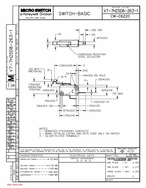

ISOMETRIC
TITLE
SCALEDATEDRDWGREVTHE INFORMATION CONTAINED IN THIS DOCUMENT IS PROPRIETARYTO E-SWITCH AND IS NOT TO BE COPIED OR TRANSFERREDSHEET OF
REVPCR NODESCRIPTIONDATEBYEG1260BSQ
6:110/7/2003D041201EAR1 1
123
CIRCUIT DIAGRAM1.30[.051 in].40[.016 in]1.50[.059 in]3.00[.118 in]
.40[.016 in]
.40[.016 in]
1.40[.055 in]
.50[.020 in].20[.008 in].50[.020 in]6.70[.264 in]
3.00[.118 in].70[.028 in]n2.70[.106 in]
.90[.035 in]2.50[.098 in]
1.10[.043 in]
.15[.006 in]0.2 CHAMFER
TYP.
0.2 CHAMFER
TYP.1.00[.039 in]NOTES:
1. ALL DIMENSIONS IN MM [INCH]
2. GENERAL TOLERANCE: X.X=`0.4
X.XX=`0.25
3. TERM. NOS. FOR REF. ONLY
4. RATING: 0.3A, 4VDC
5. PLATING: 40 MICRO INCHES NICKEL
W/40 MICRO INCHES OF SILVER
6. OPERATING FORCE: 150`100GF
7. OPERATING LIFE: 10,000 CYCLES
8. TRAVEL: 1.5OMM
9. DENOTES CRITICAL PARAMETER.7.70[.303 in]P.C.B. LAYOUT
STK525.............................................................................................Hardware User GuideSTK525 Hardware User Guide User Guide1
7608A–AVR–04/06Section 1Introduction...........................................................................................1-31.1Overview...................................................................................................1-31.2STK525 Starter Kit Features.....................................................................1-4Section 2Using the STK525.................................................................................2-62.1Overview...................................................................................................2-62.2Power Supply............................................................................................2-72.3RESET....................................................................................................2-102.4AT90USBxxx AVR Microcontroller..........................................................2-112.5Serial Links.............................................................................................2-112.6On-board Resources...............................................................................2-142.7STK500 Resources.................................................................................2-192.8In-System Programming.........................................................................2-202.10Test Points..............................................................................................2-232.11Configuration Pads.................................................................................2-242.12Solder Pads............................................................................................2-25Section 3Troubleshooting Guide.......................................................................3-26Section 4Technical Specifications.....................................................................4-27Section 5Technical Support...............................................................................5-28Section 6Complete Schematics.........................................................................6-29STK525 Hardware User Guide1-3 7608A–AVR–04/06Section 1IntroductionCongratulation for acquiring the AVR® STK525 Starter Kit. This kit is designed to givedesigners a quick start to develop code on the AT90USBxxx and for prototyping andtesting of new designs.1.1OverviewThis document describes the STK525 dedicated to the AT90USBxxx AVRmicrocontroller. This board is designed to allow an easy evaluation of the product usingdemonstration software.To complement the evaluation and enable additional development capability, theSTK525 can be plugged into the Atmel STK500 Starter Kit Board in order to use theAT90USBxxx with advanced features such as variable VCC, variable VRef, variableXTAL, etc. and supports all AVR development tools.To increase its demonstrative capabilities, this stand alone board has numerous on-board resources (USB, RS232, joystick, data-flash, microphone and temperaturesensor).This user guide acts as a general getting started guide as well as a complete technicalreference for advanced users.Introduction1-4STK525 Hardware User Guide7608A–AVR–04/06Figure 1-1 . STK525 Board1.2STK525 Starter Kit FeaturesThe STK525 provides the following features:AT90USBxxx TQFP device (2.7V
1(4) SCL1700-D01 Product Specification Jan. 20, 2006
VTI Technologies Oy VAT Reg. Business ID 1749605-7 Domicile Vantaa
SCL1700-D01 PRODUCT SPECIFICATION
/ 2(4) SCL1700-D01 Product Specification Jan. 20, 2006
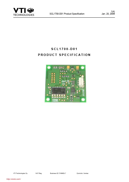
VTI Technologies Oy VAT Reg. Business ID 1749605-7 Domicile Vantaa 1 General description This document describes an inclination module, suitable for various industrial applications. Inclinometer is available in 2 axis configuration. The sensor used is a VTI standard inclinometer component SCA100T-D01. Output interface is analogue voltage. 1.1 Block diagram Products are based on SCA100T-D01 components, mounted on PCB. Electronics are not encapsulated. 1.2 Inclinometer Features • Measuring range: ±10° • Controlled frequency response • Easy to use and design in • High resolution analogue output • Dual axis inclination measurement • Advanced failure detection • Wide supply voltage range Benefits • Excellent long term stability • Outstanding shock durability • Harsh environment robustness • Fit, form and function compatible with commonly used 45 x 45mm dual axis inclination board

Features
• One of a Family of 9 Devices with User Memories from 1-Kbit to 256-Kbit • 256-Kbit (32-Kbyte) EEPROM User Memory ⎯ Sixteen 2-Kbyte (16-Kbit) Zones ⎯ Self-timed Write Cycle ⎯ Single Byte or 128-byte Page Write Mode ⎯ Programmable Access Rights for Each Zone • 2-Kbit Configuration Zone ⎯ 37-byte OTP Area for User-defined Codes ⎯ 160-byte Area for User-defined Keys and Passwords • High Security Features ⎯ 64-bit Mutual Authentication Protocol (Under License of ELVA) ⎯ Encrypted Checksum ⎯ Stream Encryption ⎯ Four Key Sets for Authentication and Encryption ⎯ Eight Sets of Two 24-bit Passwords ⎯ Anti-tearing Function ⎯ Voltage and Frequency Monitor • Smart Card Features ⎯ ISO 7816 Class A (5V) or Class B (3V) Operation ⎯ ISO 7816-3 Asynchronous T = 0 Protocol (Gemplus® Patent) * ⎯ Supports Protocol and Parameters Selection for Faster Operation ⎯ Multiple Zones, Key Sets and Passwords for Multi-application Use ⎯ Synchronous 2-wire Serial Interface for Faster Device Initialization * ⎯ Programmable 8-byte Answer-To-Reset Register ⎯ ISO 7816-2 Compliant Modules • Embedded Application Features ⎯ Low Voltage Operation: 2.7V to 5.5V ⎯ Secure Nonvolatile Storage for Sensitive System or User Information ⎯ 2-wire Serial Interface ⎯ 1.0 MHz Compatibility for Fast Operation ⎯ Standard 8-lead Plastic Packages, Green Compliant (exceeds RoHS) ⎯ Same Pinout as 2-wire Serial EEPROMs • High Reliability ⎯ Endurance: 100,000 Cycles ⎯ Data Retention: 10 years ⎯ ESD Protection: 4,000V min * Note: Modules available with either T=0 / 2-wire modes or 2-wire mode only.