川崎主泵构造原理及调试
- 格式:ppt
- 大小:5.76 MB
- 文档页数:29
川崎液压系统的设计原理分析分析挖掘机中应用广泛的川崎系统,介绍其系统结构原理和关键功能,并对挖掘机液压故障提出故障诊断步骤探讨,能对挖掘机液压系统普遍性故障排查有指导作用。
标签:川崎系统;液压;挖掘机近年来,国内港口矿物码头虽然频繁有许多高效率、环保节能的新型工程机械如堆取料机、全自动皮带系统等亮相,但液压挖掘机仍是矿物码头不可替代的主力机械,它负责码头堆场矿物的堆垛、加高、转堆以及联合门吊或卸船机交叉卸船作业,其工作内容和范围十分广泛。
而针对不同品牌和型号的挖掘机,其结构和设计上都存在一定的共性,以湛江港三分公司为例,早年投入使用的日立ZAXIS200,近年引进的现代R220、R330的7系列和9系列挖掘机,其液压系统特点均使用川崎液压设计,因此,研究分析川崎液压系统,对于一般性故障如何能快速判断、检测、故障排除有着重要意义。
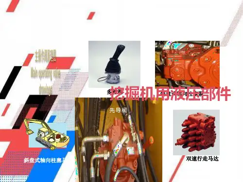
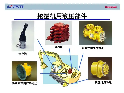
1 川崎液压系统功能设计分析川崎液压系统因其结构简单,系统响应快,维护方便等优点在挖掘机结构体系中被广泛使用,以现代R225LC-7为例,结构可简单概括为“一泵一阀四缸三马达”,其中一泵是指液压主泵,它是驱动整个液压系统的动力源;一阀是指主控阀,也称多路分配阀,是将来自于泵的高压油根据先导控制油路信号再分配到工作制动器。
四缸三马达则是挖掘机的动力输出装置,主要负责行走、旋转和油缸臂动作。
因此,从功能上看,整个液压系统包含了三大油路:(1)先导控制油路;(2)基础油路;(3)工作辅助油路。
1.1 先导控制油路先导控制油路由先导泵供油,经过滤油器和先导溢流阀(3.5kgf/cm2),然后大致分为三条线路:(1)是向主要液压器件提供常压油,如液压主泵EPPR阀提供私服压力(35bar)、回转马达驻车制动常压供油、主控阀行走信号测压点常压油等。
(2)是通过安全锁定电磁阀向操作手柄和踏板提供控制油,再反馈到主控阀相应的阀芯控制基础油路实现动作。
(3)是向电磁阀组件提供压力信号油。
1.2 基础油路基础油路是川崎系统的核心部分,它包括吸油油路(主泵端)、分配油路(主控阀端)和回油泄漏油路三部分,三种油路形成闭环控制。
川崎K3V系列斜盘式轴向柱塞泵使用说明书川崎重工业株式会社液压泵一、概述:液压泵将原动机的机械能转换成工作液体的压力能。
按其职能系统,属于液压能源元件,又称为动力元件。
液压传动中使用的液压泵都是靠密闭的工作空间的容积变化进行工作的,所以又称为容积式液压泵。
液压泵可分为齿轮泵,叶片泵,柱塞泵(按结构来分)本节主要介绍挖掘机上常用的齿轮泵、柱塞泵的基本概念、工作原理、结构特点、运用原理和维修知识。
1、液压泵的基本性能参数液压泵的主要性能参数是压力P 和流量Q(1)压力泵的输出压力由负载决定。
当负载增加时,泵的压力升高,当负载减小,泵的压力降低,没有负载就没有压力。
所以,在液压系统工作的过程中,泵的压力是随着负载的变化而变化的。
如果负载无限制的增长。
泵的压力也无限制的增高。
直至密封或零件强度或管路被破坏。
这是容积式液压泵的一个重要特点。
因此在液压系统中必须设置安全阀。
限制泵的最大压力,起过载保护作用。
在位置的布置上,安全阀越靠近泵越好。
液压泵说明书对压力有两种规定:额定压力和最大压力。
额定压力——是指泵在连续运转情况下所允许使用的工作压力,并能保证泵的容积效率和使用寿命。
最大压力——泵在短时间内起载所允许的极限压力,为液压系统的安全阀的调定值不能超过泵的最大压力值,最好的是等于或小于额定压力值。
(2)流量Q流量是指泵在单位时间输出液体的体积。
流量有理论流量和实际流量之分理论流量Q0,等于排量q 与泵转数的乘积:Q0=q*n*10-3(L/min)泵的排量是指泵每转一周所排出液体的体积。
泵的排量取决于泵的结构参数。
不同类型泵的排量记算方法也不同。
排量不可变的称为定量泵,排量可变的称为变量泵。
泵的实际流量Q小于理论流量Q0(因为泵的各密封间隙有泄漏)Q= Q0ηV = q.n.ηV /1000(L/min)式中ηV----泵的容积效率ηV =(Q(实际流量)/ Q0(理论流量))*100%齿轮泵的容积效率,ηV≥92%,柱塞泵ηV≥95%泵的泄漏量(漏损)与泵的输出压力有关,压力升高泄漏量(Q0-Q)即ΔQ增加,所以泵的实际流量是随泵的输出压力变化而变化的,而液压泵的理论流量与泵的输出压力无关。
Group 1 Pump Device2-1 Group 2 Main Control Valve2-21 Group 3 Swing Device2-46 Group 4 Travel Device2-58 Group 5 RCV Lever2-69 Group 6 RCV Pedal2-761. STRUCTUREThe pump device consists of main pump, regulator and gear pump.The main pump consists of two piston pumps(front & rear) and valve block.04Gear pump 251Support710O-ring 111Drive shaft(F)261Seal cover(F)717O-ring 113Drive shaft(R)271Pump casing 724O-ring 114Spline coupling 312Valve block 725O-ring 123Roller bearing 313Valve plate(R)728O-ring 124Needle bearing 314Valve plate(L)732O-ring 127Bearing spacer 401Hexagon socket bolt 774Oil seal141Cylinder block 406Hexagon socket bolt 789Back up ring 151Piston 466VP Plug 792Back up ring152Shoe 468VP Plug 806Hexagon head nut 153Set plate 490Plug808Hexagon head nut 156Bushing531Tilting pin 824Snap ring 157Cylinder spring 532Servo piston 885Pin158Spacer 534Stopper(L)886Spring pin 211Shoe plate 535Stopper(S)901Eye bolt 212Swash plate 548Pin 953Set screw 214Bushing 702O-ring 954Set screw72872579Proportional reducing valve 541Seat 543Stopper 1544Stopper 2545Steel ball544543545541079VIEW APort A B Pi PmPort nameDelivery portSuction portPilot portQmax cut portport size3/4"2 1/2"PF 1/4-15PF 1/4-15VIEW C412Hexagon socket screw 413Hexagon socket screw 436Hexagon socket screw 438Hexagon socket screw 496Plug601Casing611Feed back lever612Lever(1)613Lever(2)614Fulcrum plug615Adjust plug621Compensator piston 622Piston case623Compensator rod 624Spring seat(C)625Outer spring626Inner spring627Adjust stem(C)628Adjust screw(C)629Cover(C)630Lock nut 631Sleeve, pf641Pilot cover642Pilot cover(QMC)643Pilot piston644Spring seat(Q)645Adjust stem(Q)646Pilot spring647Stopper648Piston(QMC)651Sleeve652Spool653Spring seat654Return spring655Set spring656Block cover708O-ring722O-ring723O-ring724O-ring725O-ring728O-ring730O-ring732O-ring733O-ring734O-ring735O-ring755O-ring756O-ring763O-ring801Nut814Snap ring836Snap ring858Snap ring874Pin875Pin887Pin897Pin898Pin924Set screw925Adjust screw(QI)GEAR PUMP 3)307Poppet 308Seat309Spring seat 310Spring 311Screw 312Nut351Gear case 353Drive gear354Driven gear355Filter361Front case433Flange socket434Flange socket435Flange socket466Plug700Ring710O-ring725O-ring732O-ring850Snap ring850 355Rotary groupThe rotary group consists of drive shaft (F)(111), cylinder block(141), piston shoes(151,152), set plate(153), spherical bush(156), spacer(158) and cylinder spring(157). The drive shaft is supported by bearing(123,124) at its both ends.The shoe is caulked to the piston to from a spherical coupling. It has a pocket to relieve thrust force generated by loading pressure and the take hydraulic balance so that it slides lightly over the shoe plate(211). The sub group composed by a piston and a shoe is pressed against the shoe plate by the action of the cylinder spring via a retainer and a spherical bush.Similarly, the cylinder block is pressed against valve plate(313) by the action of the cylinder spring.Swash plate groupThe swash plate group consists of swash plate(212), shoe plate(211), swash plate support(251), tilting bush(214), tilting pin(531) and servo piston(532).The swash plate is a cylindrical part formed on the opposite side of the sliding surface of the shoe and is supported by the swash support.If the servo piston moves to the right and left as hydraulic force controlled by the regulator is admitted to hydraulic chamber located on both sides of the servo piston, the swash plate slides over the swash plate support via the spherical part of the tilting pin to change the tilting angle()2. FUNCTIONMAIN PUMPThe pumps may classified roughly into the rotary group performing a rotary motion and working as the major part of the whole pump function: the swash plate group that varies the delivery rates: and the valve cover group that changes over oil suction and discharge.1)(1) (2)157211123111151152124313141158156153Valve block groupThe valve block group consists of valve block(312), valve plate(313) and valve plate pin(885).The valve plate having two melon-shaped ports is fixed to the valve block and feeds and collects oil to and from the cylinder block.The oil changed over by the valve plate is connected to an external pipeline by way of the valve block.Now, if the drive shaft is driven by a prime mover(electric motor, engine, etc), it rotates the cylinder block via a spline linkage at the same time. If the swash plate is tilted as in Fig(previous page) the pistons arranged in the cylinder block make a reciprocating motion with respect to the cylinder block, while they revolve with the cylinder block.If you pay attention to a single piston, it performs a motion away from the valve plate(oil sucking process) within 180degrees, and makes a motion towards the valve plate(or oil discharging process)in the rest of 180 degrees. When the swash plate has a tilting angle of zero,the piston makes no stroke and discharges no oil.(3)313885312Negative flow controlBy changing the pilot pressure Pi, the pump tilting angle(delivery flow) is regulated arbitrarily, as shown in the figure.This regulator is of the negative flow control in which the delivery flow Q decreases as the pilot pressure Pi rises.With this mechanism, when the pilot pressure corresponding to the flow required for the work is commanded, the pump discharges the required flow only,and so it does not consume the power uselessly.REGULATORRegulator consists of the negative flow control, total horse power control and power shift control function.2)(1) iAs the pilot pressure Pi rises, the pilot piston(643) moves to the right to a position where the force of the pilot spring(646) balances with the hydraulic force.The groove(A) in the pilot piston is fitted with the pin(875) that is fixed to lever 2(613). Therefore, when the pilot piston moves, lever 2 rotates around the fulcrum of point B [fixed by the fulcrum plug(614) and pin(875)]. Since the large hole section(C) of lever 2 contains a protruding pin(897) fixed to the feedback lever(611), the pin(897) moves to the right as lever 2 rotates. Since the opposing-flat section(D) of the feedback lever is fitted with the pin(548) fixed by the tilting pin(531) that swings the swash plate, the feedback lever rotates around the fulcrum of point D, as the pin(897) moves.Since the feedback lever is connected with the spool(652) via the pin(874), the spool moves to the right.The movement of the spool causes the delivery pressure P1 to connect to port CL through the spool and to be admitted to the large diameter section of the servo piston. The delivery pressure P1 that is constantly admitted to the small diameter section of the servo piston moves the servo piston to the right due to the area difference, resulting in decrease of the tilting angle. When the servo piston moves to the right, point D also moves to the right. The spool is fitted with the return spring(654) and is tensioned to the left at all times, and so the pin(897) is pressed against the large hole section(C) of lever 2.Therefore, as point D moves, the feedback lever rotates around the fulcrum of point C, and the spool is shifted to the left. This causes the opening between the sleeve(651) and spool(652) to close slowly, and the servo piston comes to a complete stop when it closes completely.As the pilot pressure Pi decreases, the pilot piston(643) moves to the left by the action of the pilot spring(646) and causes lever 2(613) to rotate around the fulcrum of point B. Since the pin(897) is pressed against the large hole section(C) of lever 2 by the action of the return spring(654) via the spool(652), pin(874), and feedback lever(611), the feedback lever rotates around the fulcrum of point D as lever 2 rotates, and shifts the spool to the left. Port CL opens a way to the tank port as the spool moves. This deprives the large diameter section of the servo piston of pressure, and shifts the servo piston to the left by the discharge pressure P1 in the small diameter section, resulting in an increase in the flow rate.As the servo piston moves, point D also moves to the left, the feedback lever rotates around the fulcrum of point C, and the spool moves to the right till the opening between the spool and sleeve is closed.The flow control characteristic can be adjusted with the adjusting screw.Adjust it by loosening the hexagon nut(801) and by tightening(or loosening)the hexagonal socket head screw(924).Tightening the screw shifts the control chart to the right as shown in the figure.Adjusting values are shown in table.Adjustment of flow control characteristic i801924Total horsepower controlThe regulator decreases the pump tilting angle(delivery flow) automatically to limit the input torque within a certain value with a rise in the delivery pressure P1 of the self pump and the delivery pressure P2 of the companion pump.(The input horsepower is constant when the speed is constant.)Since the regulator is of the simultaneous total horsepower type that operates by the sum of load pressures of the two pumps in the tandem double-pump system, the prime mover is automatically prevented from being overloaded,irrespective of the load condition of the two pumps, when horsepower control is under way.Since this regulator is of the simultaneous total horsepower type, it controls the tilting angles(displacement volumes) of the two pumps to the same value as represented by the following equation :Tin = P1¡q/2¬+ P2¡q/2¬= (P1+P2)¡q/2¬The horsepower control function is the same as the flow control function and is summarized in the following.(For detailed behaviors of respective parts, refer to the section of flow control).(2)Overload preventive functionWhen the self pump delivery pressure P1 or the companion pump delivery pressure P2 rises, it acts on the stepped part of the compensating piston(621). It presses the compensating rod(623) to the right till the force of the outer spring(625) and inner spring(626) balances with the hydraulic force. The movement of the compensating rod is transmitted to lever 1(612) via pin(875).Lever 1 rotates around the pin(875) (E) fixed to the casing(601).Since the large hole section(F) of lever 1 contains a protruding pin(897) fixed to the feedback lever(611), the feedback lever rotates around the fulcrum of point D as lever 1 rotates, and then the spool(652) is shifted to the right. As the spool moves, the delivery pressure P1 is admitted to the large diameter section of the servo piston via port CL, causes the servo piston move to the right, reduces the pump delivery, flow rate, and prevents the prime mover from being overloaded.The movement of the servo piston is transmitted to the feedback lever via point D. Then the feedback lever rotates around the fulcrum of point F and the spool is shifted to the left. The spool moves till the opening between the spool(652) and sleeve(651) is closed.Flow reset functionAs the self pump delivery pressure P1 or the companion pump delivery pressure P2 decreases, the compensating rod(623) is pushed back by the action of the springs(625 & 626) to rotate lever 1(612) around point E. Rotating of lever 1 causes the feedback lever(611) to rotate around the fulcrum of point D and then the spool(652) to move to the left. As a result, port CL opens a way to the tank port.This causes the servo piston to move to the left and the pump's delivery rate to increase.The movement of the servo piston is transmitted to the spool by the action of the feedback mechanism to move it till the opening between the spool and sleeve is closed.Adjustment of outer springAdjust it by loosening the hexagon nut(630) and by tightening(or loosening) the adjusting screw C(628).Tightening the screw shifts the control chart to the right and increases the input horsepower as shown in the figure. Since turning the adjusting screw C by N turns changes the setting of the inner spring(626), return the adjusting screw QI(925) by N¡ A turns at first.(A=2.2)Adjusting values are shown in tableLow tilting angle(Low flow) command preferential functionAs mentioned above, flow control and horsepower control tilting angle commands are transmitted to the feedback lever and spool via the large-hole sections(C & F) of levers 1 and 2.However, since sections C and F have the pins(¨4) protruding from the large hole(¨8), only the lever lessening the tilting angle contacts the pin(897) ; the hole(¨8) in the lever of a larger tilting angle command is freed without contacting the pin(897). Such a mechanical selection method permits preference of the lower tilting angle command of the flow control and horsepower control.Adjustment of input horsepowerSince the regulator is of total cumulative horsepower type, adjust the adjusting screws of both the front and rear pumps, when changing the horsepower set values. The pressure change values by adjustment are based on two pumps pressurized at the same time, and the values will be doubled when only one pump is loaded.a.Adjustment of outer springSpeedTightening Compens- Input torque amount of ating control change adjusting starting amount screw(C)pressure (924)changeamount(min -1)(Turn)(kgf/cm 2)(kgf¡m)2100+1/4+15.9+4.2b.Adjustment of inner spring Array Adjust it by loosening the hexagon nut (801) and by tightening(or loosening) the adjusting screw QI(925).Tightening the screw increases the flow and then the input horsepower as shown in the figure.Adjusting valves are shown in tablePower shift controlattached to the pump.valve is provided.horsepower level.This function permits arbitrary setting of the pump output power, thereby providing the optimum power level according to the operating condition.The power shift pressure Pf controls the set horsepower of the pump to a desired level, as shown in the figure.As the power shift pressure Pf rises, the compensating rod(623) moves to the right via the pin(898) and compensating piston(621).This decreases the pump tilting angle and then the set horsepower in the same way as explained in the overload preventive function of the horsepower control. On the contrary, the set horsepower rises as the power shift pressure Pf falls.(3)Adjust it by loosening the hexagon nut(808) and by tightening(or loosening)the set screw(954).The maximum flow only is adjusted without changing other control characteristics.Adjustment of minimum flowAdjust it by loosening the hexagon nut(808) and by tightening(or loosening)the hexagonal socket head set screw (953). Similarly to the adjustment of the maximum flow, other characteristics are not changed.However, remember that, if tightened too much, the required horsepower during the maximum delivery pressure(or during relieving) may increase.Adjustment of maximum and minimum flows (4)Adjustment of min flow Speed(min -1)2100Tightening amount of adjusting screw(953)(Turn)+1/4Flow change amount(/min )+4.8808954806953i(5)Qmax cut controlintermediate level.)Functional explanationAs shown in the figure, the pilot pressuresteps.When the pilot pressure Pm is given, it isadmitted to the lefthand side of thepiston QMC(648). The piston QMCmoves the stopper(647) and pilotpiston(643) to the right, overcoming theforce of the pilot spring(646), therebyreducing the delivery flow of the pump.Since the adjusting screw QMC(642) isprovided with a flange, the piston QMCstops upon contact with the flange, andthe position of the pilot piston at this timedetermines the maximum flow of thepump.Adjustment of Qmax cut flowAdjust it by loosening the hexagonnut(801) and by tightening(or loosening)the adjusting screw QMC(642).Tightening the screw decreases theQmax cut flow as shown in the figure.2-20。
川崎泵的工作原理川崎泵是世界上知名的流量调节设备之一,应用于许多工业和商业领域。
所谓川崎泵就是指一种能够将液体或气体从一个容器转移到另一个容器的机械设备。
它通过应用物理和机械原理来转移液体或气体。
本文将详细讲述川崎泵的工作原理。
1. 川崎泵的主要组成部分川崎泵的主要组成部分包括泵体、叶轮、密封件、轴承和驱动器。
泵体是整个泵的主体部分,它的内部容积增大,从而使进口压力较低的液体或气体向高压部分流动。
叶轮是泵的核心部件,它会由马达或电动机带动旋转,进而推动纵向流动的流体。
密封件用于密封泵的出口和进口,以防止泄漏。
轴承用于支撑叶轮和驱动器的运动,保证泵的平衡和稳定。
驱动器则是泵的动力来源,提供能量以推动泵体和叶轮。
2. 川崎泵的工作原理在川崎泵的工作过程中,通常将液体或气体借助泵的叶轮进行转移。
泵体和叶轮间存在很小的隙缝,这个隙缝大小对川崎泵的性能影响很大。
通常情况下,隙缝越小,泵从一个区域向另一个区域的压力差就越小。
这将导致泵的工作效率降低,而且不适用于高粘度流体的处理。
因此,合理的隙缝可以使泵的性能达到最佳状态。
当启动川崎泵时,液体或气体从泵体口进入泵。
泵的内部密闭空间随后会产生负压,强制将液体或气体从进口吸入密闭空间。
这可以通过叶轮与驱动器的旋转来推动液体或气体,将它们从泵体的进口推到出口,向更高的压力区域移动。
绕流和密封件将压缩液体或气体向泵的出口推送。
然后,密封件将泵托盘和泵体连接起来,以保证造成泄漏。
最后,液体或气体从泵的出口喷出并进入用于转移或处理的容器。
3. 川崎泵的应用川崎泵在很多工业和商业领域中都得到了广泛应用。
例如,它可以应用于石油和天然气开采过程中,以将石油和天然气从井底提到地面。
此外,川崎泵也被应用于水系统中,以推动水从一个地方到另一个地方,疏通阀门和管道。
它还可以被用于泵送高粘度物料,如沥青,涂料,颜料,粘合剂和高浓度的化学液体。
总之,川崎泵是一种广泛应用的流量调节设备。
它的工作原理其实很简单,通过叶轮的旋转驱动液体或气体流动从而完成转移或处理。
川崎K3V泵调节器动作1)通过泵的控制压力控制之与操作杆行程成比例的二级先导压力,在选择器阀中转化成压力Pi 后,进入泵的调节器。
泵调节器得知操作杆的状态,从而控制泵的斜盘角度。
控制结果有流量增加和流量减少两种。
2)通过自身或另一泵输油压力控制(恒扭矩控制)通过自身输油压力和另一泵输油压力进行泵控制,具有一下两种功能:流量减少(防过载)功能,流量增加(流量恢复)功能。
流量减少(防过载)功能,当负载(压力)增加时,泵流量减少,因此发动机不会过载。
流量增加(流量恢复)功能,当负载(压力)减少时,泵流量增加,因此发动机输出功率可得到有效利用。
3)通过来自功率控制电磁阀的先导压力控制(转速传感控制)当扭矩控制电磁阀(位于泵2的调节器上)提供扭矩控制压力P时,f泵流量减少。
4)通过来自泵最大流量限制电磁阀的先导压力控制(泵最大流量控制)通过来自泵最大流量限制电磁阀的先导压力控制的操作,与通过泵控制压力控制相同。
油路中的泵最大流根据来自MC(主控制器)的信号,泵控制压力Pi量限制电磁阀器起作用。
泵最大流量限制电磁阀起减压作用,限制泵控制压力Pi5)通过最大流量转换电磁阀控制(仅限泵1)当泵1最大流量转换电磁阀起作用时,作用在制动器上的泵1最大流进入液压邮箱,由于止动器向右移动,先导柱塞向右量转换压力Pic移动得要比一般情况下更多,使泵的最大流量增加。
6)较小斜盘角度或较小流量信号优先控制当泵流量增加和减少信号同时到达时,泵调节器动作,使流量减少信号优先。
由泵控制器提供泵排量角度控制信号,扭矩控制电磁阀提供先导压力,通过杆A和杆B上的孔以及销6传递到反馈杆和伺服阀芯上,销6与杆A或杆B上的流量减少侧与孔相接触,使流量和功率减少控制优先。

现在的挖掘机多为斜盘式变量双液压泵,所谓变量泵就是泵的排量可以改变,它是通过改变斜盘的摆角来改变柱塞的行程从而实现泵排出油液容积的变化。
变量泵的优点是在调节范围之内,可以充分利用发动机的功率,达到高效节能的效果,但其结构和制造工艺复杂,成本高,安装调试比较负责。
按照变量方式可分为手动变量、电子油流变量、负压油流变量、压力补偿变量、恒压变量、液压变量等多种方式。
现在的挖掘机多采用川崎交叉恒功率调节系统,多为反向流控制,功率控制,工作模式控制(电磁比例减压阀控制)这三种控制方式复合控制。
下载(44.84 KB)前天21:51调节器代码对应的调节方式下载(64.54 KB)前天21:51调节器内部结构各种控制都是通过调节伺服活塞来控制斜盘角度,达到调节液压泵流量的效果。
大家知道在压强相等的情况下,受力面积的受到的作用力就大。
下载(25.52 KB)前天21:52调节器就是运用这一原理,通过控制伺服活塞的大小头与液压泵出油口的联通关闭来控制伺服活塞的行程。
在伺服活塞大小头腔都有限位螺丝,所以通过调节限位螺丝可以调节伺服活塞最大或最小行程,达到调节液压泵的最大流量或者最小流量的效果。
下载(55.63 KB)前天21:51向内调整限制伺服活塞最大和最小行程及限制最大流量和最小流量要谈谈反向流控制,就必须要弄明白反向流是如何产生的。
在主控阀中有一条中心油道,当主控阀各阀芯处于中位时(及手柄无操作时)或者阀芯微动时(及手柄微操作时)液压泵的液压油通过中心油道到达主控阀底部溢流阀,经过底部溢流阀的增压产生方向流(注当发动机启动后无动作时液压回路是直通油箱,液压系统无压力)。
下载(57.08 KB)昨天00:30所以方向流控制的功能是减少操作控制阀在中位时,泵的流量,使泵流量随司机操作所属流量变化,改善调速性能,避免了无用能耗。
大家注意方向流控制并非交叉控制,一个泵对应一个主控阀块(一般主控阀都为双阀块)。
如果单边手柄动作速度很慢特别是回转和铲斗奇慢,复合动作正常一般就是反向流油管安装反了。