Xylan1000系列干膜润滑剂卓越高性能涂料
- 格式:pdf
- 大小:933.78 KB
- 文档页数:2
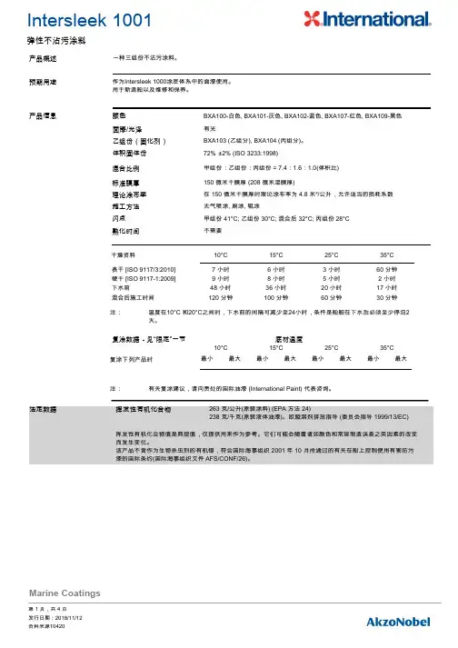
一种三组份不沾污涂料。
产品概述作为Intersleek 1000涂层体系中的面漆使用。
用于新造船以及维修和保养。
预期用途BXA100-白色, BXA101-灰色, BXA102-蓝色, BXA107-红色, BXA109-黑色72% ±2% (ISO 3233:1998)150 微米干膜厚 (208 微米湿膜厚)在 150 微米干膜厚时理论涂布率为 4.8 米²/公升,允许适当的损耗系数无气喷涂, 刷涂, 辊涂产品信息体积固体份标准膜厚理论涂布率施工方法面漆/光泽有光乙组份(固化剂)BXA103 (乙组分), BXA104 (丙组分)。
混合比例甲组份:乙组份:丙组份 = 7.4:1.6:1.0(体积比)闪点甲组份 41°C; 乙组份 30°C; 混合后 32°C; 丙组份 28°C 熟化时间不需要复涂数据-见“限定”一节底材温度颜色干燥资料10°C 15°C 25°C 35°C 温度在10°C 和20°C之间时,下水前的间隔可减少至24小时,条件是船舶在下水后必须至少停泊2天。
注:表干 [ISO 9117/3:2010]7 小时 6 小时 3 小时60 分钟 硬干 [ISO 9117-1:2009]9 小时8 小时 5 小时 2 小时 下水前48 小时36 小时20 小时17 小时 混合后施工时间120 分钟100 分钟60 分钟30 分钟复涂下列产品时10°C15°C25°C35°C最小最大最小最大最小最大最小最大有关复涂建议,请向贵处的国际油漆 (International Paint) 代表咨询。
注:法定数据挥发性有机化合物挥发性有机化合物值是典型值,仅提供用来作为参考。
它们可能会随着诸如颜色和常规制造误差之类因素的改变而发生变化。

WTM-1000Laboratory Grade, Bench TopMini Wind TunnelAnemometer Sold Separatelye-mail:**************For latest product manuals:Shop online at ®User’s Guide®U.S.A.: **************Omega Engineering, Inc:800 Connect i cut Ave. Suite 5N01, Norwalk, CT 06854, USA Toll-Free: 1-800-826-6342 (USA & Canada on l y)Customer Service: 1-800-622-2378 (USA & Canada only) Engineering Service: 1-800-872-9436 (USA & Canada only) Tel: (203) 359-1660e-mail: i nfo@ome g Omega Engineering,limited:1 Omega Drive, Northbank,lrlam Manchester M44 5B0Un i ted KingdomFax: (203) 359-7700Omega Engineering,GmbH:Da i m l erstrasse 26 75392Deckenpfronn GermanyFor Other Locations Visit/worldwideThe information contained in this document is believed to be correct, but OMEGA accepts no liability for any errors it contains, and reserves the right to alter specifications without notice.PageChapter 1 Introduction (1)1.1 Description ............................................................................................ 11.2 Unpacking ............................................................................................. 1Chapter 2 Operation .. (5)2.1 Setting Up the Mini Wind Tunnel - Precautions ...................................... 52.2 Operating the Wind Tunnel .................................................................... 52.3 Correction Factors . (6)Chapter 3 Specifications ....................................................................... 8Chapter 4 In Case Of Problems ............................................................. 9Chapter 5 Maintenance ...................................................................... 10Chapter 6 Spare Parts and Replacement Parts (10)i1.3 Safety Information (2)Notes iiIntroduction1 Introduction1.1 DescriptionThe new Mini Wind Tunnel Model WTM-1000 is designed to give a highlyuniform flow rate over a 10 cm (4") diameter test chamber. The Wind Tunnel hasan electronic control unit where it controls the DC Fan speed and provides fourselectable fixed air speeds. The fixed air speeds are:2.5 m/s (492 FPM)5 m/s (984 FPM)10 m/s (1969 FPM)15 m/s (2953 FPM)In addition, there is a REMOTE selection on the electronic control unit selectorswitch. This will allow connecting an external potentiometer to control the DCfan speed and be able to vary the speed from 0 to 15 m/s. A cable to connect anexternal potentiometer to the control unit is included in the shipping box.The purchase of the WTM-1000 also includes a NIST traceable calibrationcertificate.Figure 1- Illustrates the important components of the wind tunnel as well as it’soverall dimensions (page 3). Figure 2 - Shows the front panel of the ElectronicControl Box (page 4). Figure 3 - Shows the rear panel of the Electronic ControlBox (page 4).1.2 Unpacking1.2.1Remove the packing list and verify that you have received all your equipment. Ifyou have any questions about the shipment, please call our Customer ServiceDepartment at 1-800-622-2378 or 203-359-1660. We can also be reached on theInternet at , e-mail: ******************. When you receive theshipment, inspect the container and equipment for any signs of damage. Noteany evidence of rough handling in transit. Immediately report any damage tothe shipping agent.The carrier will not honor any claims unless all shipping material issaved for their examination. After examining and removing contents,save packing material and carton in the event reshipment is necessary.With your order of the WTM-1000 Mini Wind Tunnel you get:1.Wind Tunnel2.Power Cord3.Remote Connection Cable5.Spare Fuse6.Vane/Probe Clamp Sleeve7.Chamber Door8.Vane Window Door9.Package of ten 1/4" Teflon Compression Ferrules10.NIST Traceable Calibration Certificates11.Operators manual1Call Omega Engineering for pricing and availability.2ACCESSORIES DESCRIPTIONPOWER CORD-DM Power cord with connector for DenmarkPOWER CORD-E-10A Power cord with connector for Continental Europe POWER CORD-IT Power cord with connector for Italy or Ireland POWER CORD-SE Power cord with stripped ends (no connector) All countries 250 Vac maxPOWER CORD-UK Power cord with connector for United Kingdom POWER CORD Power cord with connector for North America MOLDED(USA, Mexico, Canada) standard 120 Vac1.3 Symbols and Safety InformationSymbols UsedThe following table lists the International Electrical Symbols. Some or all these symbols may be used on the instrument or in this manual.•“WARNING” Identifies conditions and actions that may pose hazards to the user.•“CAUTION” Identifies conditions and actions that may damage the instrument being used.WARNING•No replacement cord shall be used other than the one shipped with the product.•Use equipment only as instructed in the manual, otherwise protection may be impaired and user is risking an injury.•Disconnect power from the source before changing the fuse.Alternating Current (AC)Caution/Warning: Read User’s Manual (Important Instructions)Caution. Possibility of electric shockOff OnThe following definitions apply for “WARNING” and “CAUTION”.3F i g u r e 1 - I m p o r t a n t C o m p o n e n t s o f M i n i W i n d T u n n e l a n d O v e r a l l D i m e n s i o n s4Figure 2. Front Panel, Control Unit BoxFigure 3. Back Panel, Control Unit BoxOperation2.1 Setting Up the Mini Wind Tunnel - PrecautionsA wind tunnel’s performance can be severely diminished if not used properly.Please follow the following tips:•D o not use the wind tunnel in small rooms. The air flow creates currents thatundermine the wind tunnel’s accuracy.•A void locating the intake and exhaust toward open windows, door ways orcorridors where people are walking. The effect of air current changes acrossthe intake has a severe affect on the flow rate changing in the wind tunnel.•T here should be at least 1.5 m (5 feet) clear space in front of and behind thewind tunnel. No obstacles, moving objects, or open doors or windows.•Locate the exhaust towards the largest open area of the room to minimizeroom air currents. The higher the flow rate, the more chance of creating currents.•A ir Probe geometry affects the readings. There is a correction factor table fordifferent types of air probes (Hot wire & Vane type).•T he air flow rate of the wind tunnel depends on the air temperature andbarometric pressure. Adjust it accordingly.•T his instrument should only be used for its intended purpose in accordance tothe instruction manual.2.2 Operating the Wind TunnelBefore operating the wind tunnel, please follow all the precautions stated in theprevious section and then proceed as follows:1-Connect the cable from the DC Fan to the back of the Control unitbox labeled 'Fan Control'. Make sure the power switch in the back of the controlunit is off.2- Connect the AC input of the Control unit to a line voltage (90 to 250 VAC @50/60 Hz) with the Power cord provided. Please refer to the accessory table forpower cords for other countries.3- Set the air speed selector switch on the front of the control unit to Zeroposition (Meaning Zero air velocity). Turn on the Power switch in the back. Youwill see the power LED indicator on the front of the control box turns on.The air speed selector switch can be set to four fixed air speeds. The wind tunnelhas been calibrated at these four air speeds. The standard conditions are at70ºF (21.1ºC) ambient temperature and 29.92 inches of Hg of Barometricpressure. There are four plugs in front of the control unit box. Removing theplugs, you will have access to potentiometers that will allow you to adjust the airspeed at the four settings.For Hot wire anemometers:1-Use the Chamber Door (Solid) to cover the test chamber.2-I nsert the air probe into Port #1 as shown in Fig 1. Port #2 is used to insert areference air probe if desired.3-A lign the air probe sensor to the center of the chamber using the scribed line onthe outside of the chamber.4-U se the Teflon Ferrules and “hand-tighten” the probe in place. Do not use tools orwrenches.56For Vane Type Anemometers:1-Remove the chamber door. Open the clamp in the adjustable mounting block by turning the wheel.2-Place the vane propeller inside the chamber. Make sure it is in the center of the chamber.3-Place the vane window door.4-Secure the vane propeller in place by tightening the clamp using the wheel.5-Slide the Vane Clamp sleeve over the vane window door and up against the vane probe to minimize any air leaks.Once the air probe is in place (either Hot wire or Vane type), turn the air speed selector switch from 2.5 m/s (492 FPM) up to 15 m/s (2953 FPM). Check the air probe reading vs. the switch setting on the wind tunnel.2.3 Correction FactorsFor Hot Wire Anemometers:If the environmental conditions are other than the standard conditions (70 ºF and 29.92 inches of Hg), you need to correct for them. Here is the correction factor equation:K1 = (29.92 / P) x (460 + T) / 530 where, P is the Barometric pressure in inches of Hg T is the ambient temperature in Degree FThere is a second correction factor which is a function of the air probe geometry (K2). Table 1 lists K2 for different air probes. So, the actual air velocity is as follows:Actual Value = Measured Value (Average value over one minute time) x K1 x K2For Vane type anemometers:You only need to correct for the air probe geometry (K2). The actual air velocity is as follows:Example 1:An FMA-904 Hot wire anemometer is being checked in the Wind Tunnelat 2.5 m/s (492 FPM) air speed. The Environmental conditions are: Barometric Pressure = 27.88 inches of HgAmbient Temperature = 80 ºFThe FMA-904 measures 442 FPM. Calculate the actual air speed:Actual Air speed = Measured Value (Average value over one minute time) xK1 x K2K1 = (29.92/P) x (460 + T)/530K1 = (29.92/27.88) x (460 + 80)/530K1 = 1.093FromTable1,*****************/sis1.04Actual Air speed = 442 x 1.093 x 1.04Actual Air speed = 502 FPMExample 2:An HHF92A Vane type anemometer is being checked in the Wind Tunnel at 15 m/s (2953 FPM). The HHF92A measures 2848 FPM. Calculate the actual air speed:Actual Air speed = Measured Value (Average value over one minute time) x K2 From Table 1, K2 for HHF92A @ 15 m/s is 1.04Actual Air speed = 2848 x 1.04Actual Air speed = 2962 FPM7Chapter 3 - SpecificationsAccuracy: ±1% of setting or ±0.1 m/s, whichever is larger Test Chamber: 10 cm (4") diameter Flow Rates: 2.5 m/s (492 fpm), 5.0 m/s (984 fpm), 10 m/s (1969 fpm), 15 m/s (2953 fpm)Remote Option: Use an external 5K, 10-turn potentiometer to vary air speed DC Motor: **********(26W)Power: 90 to 250 Vac @ 50/60 Hz Operating Temperature: 5 to 45°C (41 to 113°F)Operating Relative Humidity: 80% RH max without condensation Size: Weight: 8Storage Temperature : 68.5 L x 20.3 W x 29.2 cm H (27 x 8 x 11.5") 8.2 kg (18 lb)Equipment is for indoor use only.-40°C (-40°F) to 71°C (160°F)PROBLEM SOLUTION9The wind tunnel is not on - no power to control boxCheck the fuse in the motor control box - if blown, replace with same type and rating."CAUTION: For continued protection against the risk of fire, replace with only the same type, rating and size of fuse. Disconnect power from the source before changing the fuse."The wind tunnel is on - fan does not turn.Make sure the cable from the fan is connected to the motor control box.Make sure the power switch on the motor control box is “ON”.Make sure there are no obstructions around the fan area of the wind tunnel.Can’t get velocity desired.Check your AC power.Check the position of the selector switch on the motor control box.Poor repeatability.Locate the wind tunnel in room that has AT LEAST 1800 cubic feet of space.Make sure the motor control box is plugged in and connected to a live outlet. Turn on power switchChapter 5 - MaintenanceThe following points should be adhered to for a maintenance-free operation of the wind tunnel.•Make sure the wind tunnel is operating in a relatively dirt-free room. Follow the precaution tips.Chapter 6 - Spare and Replacement Parts10WTM-0014Honeycomb flow straightener WTM-0009Chamber Window Cover (Solid)IR-0032C Remote Connection Cable•There are no special instructions for cleaning the unit.•This unit has non serviceable parts. If needed, contact Omega for necessary repairs.Notes11Notes 12OMEGA’s policy is to make running changes, not model changes, whenever an improvement is possible. This affords our customers the latest in technology and engineering.OMEGA is a registered trademark of OMEGA ENGINEERING, INC.© Copyright 2014 OMEGA ENGINEERING, INC. All rights reserved. T his document may not be copied, photocopied, reproduced, translated, or reduced to any electronic medium or machine-readable form, in whole or in part, without the prior written consent of OMEGA ENGINEERING, INC.FOR WARRANTY RETURNS, please have the following information available BEFORE contacting OMEGA:1. P urchase Order number under which the product was PURCHASED,2. M odel and serial number of the product under warranty, and3.Repair instructions and/or specific problems relative to the product.FOR NON-WARRANTY REPAIRS, consult OMEGA for current repair charges. Have the following information available BEFORE contacting OMEGA:1.Purchase Order number to cover the COST of the repair,2.Model and serial number of the product, and 3.Repair instructions and/or specific problems relative to the product.RETURN REQUESTS/INQUIRIESDirect all warranty and repair requests/inquiries to the OMEGA Customer Service Department. BEFORE RET URNING ANY PRODUCT (S) T O OMEGA, PURCHASER MUST OBT AIN AN AUT HORIZED RET URN (AR) NUMBER FROM OMEGA’S CUST OMER SERVICE DEPART MENT (IN ORDER T O AVOID PROCESSING DELAYS). The assigned AR number should then be marked on the outside of the return package and on any correspondence.The purchaser is responsible for shipping charges, freight, insurance and proper packaging to prevent breakage in transit.WARRANTY/DISCLAIMEROMEGA ENGINEERING, INC. warrants this unit to be free of defects in materials and workmanship for a period of 13 months from date of purchase. OMEGA’s WARRANTY adds an additional one (1) month grace period to the normal one (1) year product warranty to cover handling and shipping time. This ensures that OMEGA’s customers receive maximum coverage on each product.If the unit malfunctions, it must be returned to the factory for evaluation. OMEGA’s Customer Service Department will issue an Authorized Return (AR) number immediately upon phone or written request. Upon examination by OMEGA, if the unit is found to be defective, it will be repaired or replaced at no charge. OMEGA’s WARRANT Y does not apply to defects resulting from any action of the purchaser, including but not limited to mishandling, improper interfacing, operation outside of design limits, improper repair, or unauthorized modification. T his WARRANT Y is VOID if the unit shows evidence of having been tampered with or shows evidence of having been damaged as a result of excessive corrosion; or current, heat, moisture or vibration; improper specification; misapplication; misuse or other operating conditions outside of OMEGA’s control. Components in which wear is not warranted, include but are not limited to contact points, fuses, and triacs.OMEGA is pleased to offer suggestions on the use of its various products. However, OMEGA neither assumes responsibility for any omissions or errors nor assumes liability for any damages that result from the use of its products in accordance with information provided by OMEGA, either verbal or written. OMEGA warrants only that the parts manufactured by the company will be as specified and free of defects. OMEGA MAKES NO OTHER WARRANTIES OR REPRESENTATIONS OF ANY KIND WHATSOEVER, EXPRESSED OR IMPLIED, EXCEPT THAT OF TITLE, AND ALL IMPLIED W ARRANTIES INCLUDING ANY W ARRANTY OF MERCHANTABILITY AND FITNESS FOR A PARTICULAR PURPOSE ARE HEREBY DISCLAIMED. LIMITATION OF LIABILITY: The remedies of purchaser set forth herein are exclusive, and the total liability of OMEGA with respect to this order, whether based on contract, warranty, negligence, indemnification, strict liability or otherwise, shall not exceed the purchase price of the component upon which liability is based. In no event shall OMEGA be liable for consequential, incidental or special damages.CONDITIONS: Equipment sold by OMEGA is not intended to be used, nor shall it be used: (1) as a “Basic Component” under 10 CFR 21 (NRC), used in or with any nuclear installation or activity; or (2) in medical applications or used on humans. Should any Product(s) be used in or with any nuclear installation or activity, medical application, used on humans, or misused in any way, OMEGA assumes no responsibility as set forth in our basic WARRANTY /DISCLAIMER language, and, additionally, purchaser will indemnify OMEGA and hold OMEGA harmless from any liability or damage whatsoever arising out of the use of the Product(s) in such a manner.Where Do I Find Everything I Need for Process Measurement and Control?OMEGA…Of Course!Shop online at SMTEMPERATUREM U Thermocouple, RTD & Thermistor Probes, Connectors, Panels & AssembliesM U Wire: Thermocouple, RTD & ThermistorM U Calibrators & Ice Point ReferencesM U Recorders, Controllers & Process MonitorsM U Infrared PyrometersPRESSURE, STRAIN AND FORCEM U Transducers & Strain GagesM U Load Cells & Pressure GagesM U Displacement TransducersM U Instrumentation & AccessoriesFLOW/LEVELM U Rotameters, Gas Mass Flowmeters & Flow ComputersM U Air Velocity IndicatorsM U Turbine/Paddlewheel SystemsM U Totalizers & Batch ControllerspH/CONDUCTIVITYM U pH Electrodes, Testers & AccessoriesM U Benchtop/Laboratory MetersM U Controllers, Calibrators, Simulators & PumpsM U Industrial pH & Conductivity EquipmentDATA ACQUISITIONM U Data Acquisition & Engineering SoftwareM U Communications-Based Acquisition SystemsM U Plug-in Cards for Apple, IBM & CompatiblesM U Data Logging SystemsM U Recorders, Printers & PlottersHEATERSM U Heating CableM U Cartridge & Strip HeatersM U Immersion & Band HeatersM U Flexible HeatersM U Laboratory HeatersENVIRONMENTALMONITORING AND CONTROLM U Metering & Control InstrumentationM U RefractometersM U Pumps & TubingM U Air, Soil & Water MonitorsM U Industrial Water & Wastewater TreatmentM U pH, Conductivity & Dissolved Oxygen InstrumentsM4360/0112。

SAPPHIRE ® Aqua-SilHighly resistant silicone grease for long term lubricationProduct OverviewROCOL ®SAPPHIREAqua-Sil is a translucent, non-toxic grease that has been designed for the lubrication of seals, ‘O’ rings, slides, slow speed bearings and other similar light to medium duty applications.SAPPHIRE Aqua-Sil has a high dielectric strength, is resistant to chemicals, oils and gases and can be used as an electrical filling compound.Water Regulations Advisory Scheme – Approved Product – Approval Number: 1203533Features and Benefits∙Excellent wide temperature resistance – ranging from -40°C to +200°C and it can protect up to +220°C for short periods.∙ Outstanding resistance to chemicals, oils and gases far superior to standard greases.∙Excellent resistance to water, including salt water, ensuring components are protected even in submerged conditions.∙ SAPPHIREAqua-Sil is approved for use in both hot and cold potable (drinking) water.∙ Suitable for use as a rubber lubricant for most rubbers (not suitable for silicone rubber). ∙ Commonly used for the assembly of rubber seals, tap washers and ‘o’ rings. ∙ Ideal lubricant for most types of plastics.∙Extremely long wet life reducing re-lubrication frequencies and in some cases can be used as a lifetime lubricant.∙High dielectric strength making it ideal for use as an electrical filling compound.Directions for Storage and Use∙SAPPHIRE Aqua-Sil can be applied manually, by a silicone grease gun, or by other methods suitable for use with silicone greases.∙ For best results the previous lubricant should be removed prior to application.∙ DO NOT USE ON SILICONE RUBBER.∙ The storage temperature should be controlled between +1°C and +40°C.∙Shelf life is 3 years from date of manufacture.Typical ApplicationsSAPPHIRE Aqua-Sil is designed for long term, light, and possibly lifetime, lubrication depending on application.SAPPHIRE Aqua-Sil is particularly suitable as a rubber assembly grease on seals, ‘O’ rings, gaskets and washers.SAPPHIRE Aqua-Sil is ideal for use where a high performance, water and chemical resistant lubricant is required such as Water Authorities, Gas & Plumbing, and most other industries where a multi-purpose water and chemical resistant silicone grease is required.SAPPHIRE Aqua-Sil excels in applications such as the assembly or repair of pneumatic/hydraulic valves & cylinders, tap & shower washers, valve seals, toys and many other applications where rubbers or plastics require a light, colourless, non-toxic lubricant for long term or possible lifetime lubrication.Pack SizesThe information in this publication is based on our experience and reports from customers. There are many factors outside our control or knowledge which affect the use and performance of our products, for which reason it is given without responsibility.Issue: 2 Date: 05-12SAPPHIRE® Aqua-SilHighly resistant silicone grease for long term lubricationSafety Data SheetsSafety data sheets are available for download from our website or may be obtained from your usual ROCOL contact.。

XYLAN 表面涂层Xylan 涂层是一种耐磨损,不粘,耐高温,持续性的腐蚀环境中应用的保护微涂层。
它区别于其他传统的含氟聚合物的一个重要点在于它是复合材料。
Xylan is a thin, continuous, protective barrier that resists chipping, galling, cold flow, temperature extremes and weathering in a wide range of corrosive environments. That’s differs from traditional Fluoropolymer coatings in one very impartment aspect that they are composite materials.Xylan 的多用途特性在作为螺栓和螺帽的涂料表现最佳,在轻易安装,防腐蚀和轻便拆除方面都显示出无比的特性。
Xylan multi-purpose characteristics of bolts and nuts as the best performing coatings, in the easy installation, removal of anti-corrosion and light areas have shown tremendous character.Xylan涂层在防海水腐蚀,抗化学品腐蚀,抗磨损等方面表现出色。
盐雾时间最高可达1000多小时。
Xylan的涂层薄但是却具有自润的性能,特备适用于水下精密设备配合的表面防腐蚀:BOP,管汇,航空和航天制造工业,风力发电等。
Xylan coating is excellent in seawater corrosion prevention, chemical resistance, and wear prevention.The salt spray test is higher than 1000 hours. The thin film which is suitable for underwater precise equipment surface corrosion prevention, it’s including BOP, pipeline,voyage spaceflight manufacturing industry, wind power generation and so on.特点:characteristic低摩擦性(低于0.055);low friction (lower than 0.055)密着粘性特征;remarkable adhesion优越抗磨损及耐粘性能;unusual resistance to wear abrasion防腐蚀性极佳;excellent resistance to corrosion不易剥落;resistance to chipping能抵抗外在环境因素:日照,咸水;resistance to the elements: sunlight, salt water适应工作温度范围—190℃到260℃;working temperature rang from:-190℃to260℃有多种颜色:available in a wide range of colors热镀锌热镀锌是一种有效的金属防腐方式,主要用于各行业的金属结构设施上。
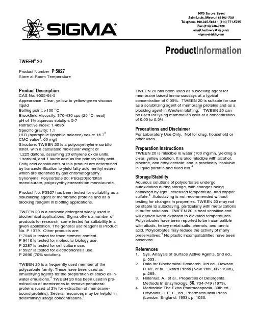
TWEEN® 20Product Number P 5927 Store at Room TemperatureProduct DescriptionCAS No: 9005-64-5Appearance: Clear, yellow to yellow-green viscous liquidBoiling point: >100 °CBrookfield Viscosity: 370-430 cps (25 °C, neat)pH of 1% aqueous solution: 5-7Refractive index: 1.46851Specific gravity: 1.1HLB (hydrophile-lipophile balance) value: 16.72CMC value3: 60 mg/lStructure: TWEEN 20 is a polyoxyethylene sorbitol ester, with a calculated molecular weight of1,225 daltons, assuming 20 ethylene oxide units,1 sorbitol, and 1 lauric acid as the primary fatty acid. Fatty acid constituents of this product are determined by transesterification to yield fatty acid methyl esters, which are identified by gas chromatography. Synonyms: Polysorbate 20; PEG(20)sorbitan monolaurate, polyoxyethylenesorbitan monolaurate. Product No. P5927 has been tested for suitability as a solubilizing agent of membrane proteins and as a blocking reagent in blotting applications.TWEEN 20 is a nonionic detergent widely used in biochemical applications. Sigma offers a number of products for research, some tested for suitability in a given application. The general use reagent is Product No. P 1379. Other products are:P 7949 is tested for trace element content.P 9416 is tested for molecular biology use.P 2287 is tested for cell culture use.P 5927 is tested for electrophoresis use.P 2690 (70% solution).TWEEN 20 is a frequently used member of the polysorbate family. These have been used as emulsifying agents for the preparation of stable oil-in-water emulsions.4 TWEEN 20 has been used in pre-extraction of membranes to remove peripheral proteins (used at 2% for extraction of membrane-bound proteins). Several resources may be helpful in determining usage concentrations.5TWEEN 20 has been used as a blocking agent for membrane based immunoassays at a typical concentration of 0.05%. TWEEN 20 is suitable for use as a solubilizing agent of membrane proteins and as a blocking agent in Western blotting.3 TWEEN 20 can be used for lysing mammalian cells at a concentration of 0.05 to 0.5%.Precautions and DisclaimerFor Laboratory Use Only. Not for drug, household or other uses.Preparation InstructionsTWEEN 20 is miscible in water (100 mg/ml), yielding a clear, yellow solution. It is also miscible with alcohol, dioxane, and ethyl acetate; and is practically insoluble in liquid paraffin and fixed oils.4Storage/StabilityAqueous solutions of polysorbates undergo autoxidation during storage, with changes being catalyzed by light, increased temperature, and copper sulfate.6 Autoclaving is not recommended without testing for changes in properties. TWEEN 20 may not be stable to autoclaving, particularly with metal cations in buffer solutions. TWEEN 20 is heat sensitive and will darken when exposed to elevated temperatures. Polysorbates have been reported to be incompatible with alkalis, heavy metal salts, phenols, and tannic acid. Polysorbates may reduce the activity of many preservatives.4 No plastic incompatabilities have been observed.References1. Sys. Analysis of Surface Active Agents, 2nd ed.,p. 533.2. Data for Biochemical Research, 3rd ed., Dawson,R. M., et al., Oxford Press (New York, NY: 1986), p. 289.3. Helenius, A., et al., Properties of Detergents.Methods in Enzymology, 56, 734-749 (1979).4. Martindale The Extra Pharmacopoeia, 30th ed.,Reynolds, J. E. F., ed., Pharmaceutical Press(London, England: 1993), p. 1030.5. Neugebauer, J.M., Detergents: An Overview.Methods in Enzymology, 182, 239-253 (1990). 6. Donbrow, M., et al., Autoxidation of polysorbates.J. Pharm. Sci., 67, 1676-1681 (1978).TWEEN is a registered trade mark of ICI Americas, Inc.RLG/AJH 5/03Sigma brand products are sold through Sigma-Aldrich, Inc.Sigma-Aldrich, Inc. warrants that its products conform to the information contained in this and other Sigma-Aldrich publications. Purchaser must determine the suitability of the product(s) for their particular use. Additional terms and conditions may apply. Please see reverse side ofthe invoice or packing slip.。

陶氏hw1000润湿剂结构式全文共四篇示例,供读者参考第一篇示例:陶氏HW1000润湿剂是一种常用于化工生产中的助剂,它具有优异的润湿性能,能够有效降低表面张力,提高润湿性能,从而提高生产效率。
本文将详细介绍陶氏HW1000润湿剂的化学结构式以及其在工业生产中的应用。
陶氏HW1000润湿剂的化学结构式为C16H34O3Si,其中包含有机硅、碳和氧元素。
其主要成分为硅氧烷,是一种无色透明的液体,具有优异的润湿性能和稳定性。
硅氧烷是一种疏水性化合物,在水中不易溶解,但可以与其他有机物发生氢键作用,从而在表面形成一层保护膜,降低表面张力,提高润湿性能。
陶氏HW1000润湿剂广泛应用于化工、电子、纺织、皮革等各个领域。
在化工生产中,它常用于表面处理剂、防锈剂、润滑剂等的配方中,可以提高产品的表面光洁度和耐磨性,提高生产效率。
在电子行业,它常用于印刷电路板、涂层等工艺中,能够改善印刷粘附性和干燥速度,提高生产质量。
在纺织和皮革行业,它常用于染整剂、防水剂等的配方中,能够提高纺织品和皮革的耐水性和光泽度,增强产品的市场竞争力。
陶氏HW1000润湿剂具有优异的环境友好性和安全性,不含有害物质,不会对人体和环境造成危害。
在工业生产中,正确使用陶氏HW1000润湿剂能够提高产品的性能和质量,降低生产成本,提高经济效益。
陶氏HW1000润湿剂在工业生产中具有广阔的应用前景。
第二篇示例:陶氏HW1000润湿剂是一种用于油墨、涂料等领域的高效润湿剂。
它具有优异的润湿性能,可以帮助涂层均匀分布在基材表面并有效降低表面张力,提高涂层的附着性和光泽度。
本文将介绍陶氏HW1000润湿剂的结构式、工作原理以及应用领域。
让我们来看一下陶氏HW1000润湿剂的结构式。
其化学式为C8H17NO3,结构式如下所示:[图1]从结构式中可以看出,陶氏HW1000润湿剂是一种含氨基的有机化合物,具有多个碳链结构。
这种结构使其在涂料和油墨中具有良好的溶解性和润湿性能,可以有效地降低表面张力,改善涂层的性能。
xylan涂层表面处理要求
Xylan涂层表面处理的要求包括以下几个方面:
1.表面清洁:在涂覆Xylan涂层之前,需要对表面进行彻底清洁,以确保表
面无杂质、油污和其他污染物。
清洁方法可以采用机械或化学方法,如研磨、喷砂、去污剂等。
2.表面干燥:处理前确保表面干燥,避免水分对涂层的影响。
3.表面粗糙度:根据涂层的要求,可能需要调整表面的粗糙度。
可以通过磨
削、喷砂等方法增加涂层与基材的粘附力,提高涂层的气密性。
4.涂料准备:遵循涂料制造商的说明,将Xylan涂料按照正确的比例混合。
涂料应由树脂和固化剂组成,确保充分混合以获得一致的涂料。
5.涂布:使用适当的涂布工具(如喷涂枪或刷子),将涂料均匀地涂布在表
面上。
确保涂料覆盖整个表面,并避免出现滴落或流淌。
6.涂层厚度:根据要求控制涂层的厚度,可以使用测量工具进行测量和调整。
7.固化:在涂层涂布完成后,按照涂料制造商的指示进行固化处理。
固化过
程中应控制温度和时间,以确保涂层的质量和性能。
需要注意的是,具体的处理要求可能会因应用场景、材料类型、涂层厚度等因素而有所不同。

©2002 Whelen Engineering Company Inc.Form No.13719A (053007)A u t o m ot ive : For warranty information regarding this product, visit /warranty•Proper installation of this product requires the installer to have a good understanding of automotive electronics, systems and procedures.•Whelen Engineering requires the use of waterproof butt splices and/or connectors if that connector could be exposed to moisture.•Any holes, either created or utilized by this product, should be made both air- and watertight using a sealant recommended by your vehicle manufacturer.•Failure to use specified installation parts and/or hardware will void the product warranty.•If mounting this product requires drilling holes, the installer MUST be sure that no vehicle components or other vital parts could be damaged by the drilling process. Check both sides of the mounting surface before drilling begins. Also de-burr the holes and remove any metal shards or remnants. Install grommets into all wire passage holes.•If this manual states that this product may be mounted with suction cups, magnets, tape or Velcro®, clean the mounting surface with a 50/50 mix of isopropyl alcohol and water and dry thoroughly.•Do not install this product or route any wires in the deployment area of your air bag. Equipment mounted or located in the air bag deployment area will damage or reduce the effectiveness of the air bag, or become a projectile that could cause serious personal injury or death. Refer to your vehicle owner’s manual for the air bag deployment area. The User/Installer assumes full responsibility to determine proper mounting location, based on providing ultimate safety to all passengers inside the vehicle.•For this product to operate at optimum efficiency, a good electrical connection to chassis ground must be made. The recommended procedure requires the product ground wire to be connected directly to the NEGATIVE (-) battery post (this does not include products that use cigar power cords).•If this product uses a remote device for activation or control, make sure that this device is located in an area that allows both the vehicle and the device to be operated safely in any driving condition. •Do not attempt to activate or control this device in a hazardous driving situation.•This product contains either strobe light(s), halogen light(s), high-intensity LEDs or a combination of these lights. Do not stare directly into these lights. Momentary blindness and/or eye damage could result.•Use only soap and water to clean the outer lens. Use of other chemicals could result in premature lens cracking (crazing) and discoloration. Lenses in this condition have significantly reduced effectiveness and should be replaced immediately. Inspect and operate this product regularly to confirm its proper operation and mounting condition. Do not use a pressure washer to clean this product.•It is recommended that these instructions be stored in a safe place and referred to when performing maintenance and/or reinstallation of this product.•FAILURE TO FOLLOW THESE SAFETY PRECAUTIONS AND INSTRUCTIONS COULD RESULT IN DAMAGE TO THE PRODUCT OR VEHICLE AND/OR SERIOUS INJURY TO YOU AND YOUR PASSENGERS!Warnings to Installers Whelen’s emergency vehicle warning devices must be properly mounted and wired in order to be effective and safe. Read and follow all of Whelen’s written instructions when installing or using this device. Emergency vehicles are often operated under high speed stressful conditions which must be accounted for when installing all emergency warning devices. Controls should be placed within convenient reach of the operator so that they can operate the system without taking their eyes off the roadway. Emergency warning devices can require high electrical voltages and/or currents. Properly protect and use caution around live electrical connections.Grounding or shorting of electrical connections can cause high current arcing, which can cause personal injury and/or vehicle damage, including fire. Many electronic devices used in emergency vehicles can create or be affected by electromagnetic interference. Therefore, after installation of any electronic device it is necessary to test all electronic equipment simultaneously to insure that they operate free of interference from other components within the vehicle. Never power emergency warning equipment from the same circuit or share the same grounding circuit with radio communication equipment. All devices should be mounted in accordance with the manufacturer’s instructions and securely fastened to vehicle elements of sufficient strength to withstand the forces applied to the device. Driver and/or passenger air bags (SRS) will affect the way equipment should be mounted. This device should be mounted by permanent installation and within the zones specified by the vehicle manufacturer, if any. Any device mounted in the deployment area of an air bag will damage or reduce the effectiveness of the air bag and may damage or dislodge the device. Installer must be sure that this device, its mounting hardware and electrical supply wiring does not interfere with the air bag or the SRS wiring or sensors. Mounting the unit inside the vehicle by a method other than permanent installation is not recommended as unit may become dislodged during swerving; sudden braking or collision. Failure to follow instructions can result in personal injury. Whelen assumes no liability for any loss resulting from the use of this warning device. PROPER INSTALLATION COMBINED WITH OPERATOR TRAINING IN THE PROPER USE OF EMERGENCY WARNING DEVICES IS ESSENTIAL TO INSURE THE SAFETY OF EMERGENCY PERSONNEL AND THE PUBLIC.Warnings to Users Whelen’s emergency vehicle warning devices are intended to alert other operators and pedestrians to the presence and operation of emergency vehicles and personnel. However, the use of this or any other Whelen emergency warning device does not guarantee that you will have the right-of-way or that other drivers and pedestrians will properly heed an emergency warning signal. Never assume you have the right-of-way. It is your responsibility to proceed safely before entering an intersection, driving against traffic, responding at a high rate of speed, or walking on or around traffic lanes. Emergency vehicle warning devices should be tested on a daily basis to ensure that they operate properly. When in actual use, the operator must ensure that both visual and audible warnings are not blocked by vehicle components (i.e.: open trunks or compartment doors), people, vehicles, or other obstructions. It is the user’s responsibility to understand and obey all laws regarding emergency warning devices. The user should be familiar with all applicable laws and regulations prior to the use of any emergency vehicle warning device. Whelen’s audible warning devices are designed to project sound in a forward direction away from the vehicle occupants. However, because sustained periodic exposure to loud sounds can cause hearing loss, all audible warning devices should be installed and operated in accordance with the standards established by the National Fire Protection Association.Safety First This document provides all the necessary information to allow your Whelen product to be properly and safely installed. Before beginning the installation and/or operation of your new product, the installation technician and operator must read this manual completely. Important information is contained herein that could prevent serious injury or damage.Installation Guide:Option Kit KDCRLED Centurion™ Lightbar Steady ID Light 51 Winthrop Road Chester, Connecticut 06412-0684Phone: (860) 526-9504Internet: Salese-mail:*******************CustomerServicee-mail:*******************®ENGINEERING COMPANY INC.IMPORTANT! The lightbar should be located a minimum of 16" Array from any radio antennas!Installation:1.Remove the two Torx head screws that secure the end cap to thebase. (Fig. 1)2.Slide the lens sections off the end of the base and remove thedividers so you may gain access to the lightbar base. (Fig. 2) Besure to note the order in which the lenses were installed on thelightbar.Note:You will notice that the lenses are seated verytightly into the lens divider gaskets to preventleaks. You will need to insert a screwdriver at eachcorner (between the black endcap and aluminumbase) and gently pry the lens out to break it freefrom the dividers. Pry each side out just a little at atime, alternating from one side to the other untilthe lens slides out easily. Before reassembling,apply a very small amount of liquid dish detergentto the sides of the rubber gaskets to help themslide in easier and obtain a better seal.3.Measure the length of the lightbar base to find the exact centerand mark it with a pencil or marker. (See next page)4.Place the lighthead assembly onto thecenter of the lightbar base.Be sure to insert the lip on the end of the take-down assembly,into the slot in the base as shown in figure 3. Secure the assembly to the channel in the lightbar base, using two of the 3/8” hexhead screws provided.Wiring:1.Secure the ground lug for the filter assembly (the BLACK wire) to the channel in the lightbar base using the 1/4” hex headscrews provided as indicated. (Fig. 4)2.Connect the provided extension with the faston connectors, to the RED wire coming from the filter assembly. Run the extensionalong the lightbar base and connect the other end it to the GREY wire (or any unused wire) in the lightbar wiring harness. Note:The cable exiting the lightbar must be fused. (Refer to Fuse & Switch Information below.)3.Neatly dress and place any loose wires under the cable clamps to avoid interference with moving parts, then replace andsecure all domes.WARNING! All customer supplied wires that connect to the positive terminal of the battery must be sized to supply at least 125% of the maximum operating current and FUSED at the battery to carry that load. DO NOT USE CIRCUIT BREAKERS WITH THIS PRODUCT!WARNING!The outer surfaces of this product may be cleaned with mild soap and water. Use of any other chemicals may void product warranty. Do not use a pressure washer.。

陶氏hw1000润湿剂结构式
陶氏HW1000润湿剂的结构式如下:
CH2=CH-CO-O-(CH2-CH2-O)n-H
其中,n代表聚合度,通常为10-20。
这是一个聚乙二醇单丙烯酸酯的结构式,属于非离子型表面活性剂。
HW1000润湿剂是陶氏化学公司(Dow Chemical Company)生产的一种高效润湿剂,广泛应用于涂料、油墨、胶粘剂、化妆品等领域。
它具有良好的润湿性能,可以降低液体表面张力,使液体更容易润湿固体表面。
此外,HW1000润湿剂还具有优异的稳定性和耐候性,能够在各种环境下保持稳定的性能。
请注意,以上信息仅供参考,如果需要更详细的信息或数据,建议查阅陶氏化学公司的官方网站或相关文献资料。
1.Trace the footprint of the niche ontothe wall.Take the pre-formed CUSTOM® ShowerInstallation Systems Shower Niche,and hold it up to the wall. It will needto be screwed into a stud, so line upone of its vertical edges with a vertical wood stud anduse a level to ensure the accuracy of your positioning. It isrecommended that you install the niche in a portrait orientation,to accommodate tall shampoo bottles. Use a pencil to trace thefootprint of the pre-formed Shower Niche onto the drywall orcement backerboard (such as CUSTOM’s WonderBoard® Lite).2.Cut the footprint out of the drywall.Use a razor or saw to cut along thelines of the footprint outline.3.Punch out the footprint.Punch out the footprint by bangingone of the corners. It should twist outnicely if the cuts were deep enough.4.Insert the shower niche.Insert the pre-formed Shower Nicheinto the wall. Shave the edges of thedrywall or backerboard if the fit istoo tight. Niche should be pushedflush with the outer surface of thewall board.5.Secure the niche with screws.Use two or more 1.5"–2" galvanizedsteel screws to secure niche againststud. You may wish to drill guideholes before you insert the niche.Two screws will secure the niche inmost instances.6.C over screws with sealant.Cover screws with CUSTOM® ShowerInstallation System Sealant andsmooth the sealant with a putty knife.1.Trace the footprint of the niche ontothe wall.Temporarily hang cement backerboard.Align the niche with a stud and tracethe footprint of the niche onto thecement backerboard. It isrecommended that you install the niche in a portrait orientation,to accommodate tall shampoo bottles. Then, cut out the hole.Remove backerboard.2.Secure the niche with screws.Screw the shower niche into thevertical stud, using two or more1.5"–2" galvanized steel screws. Youmay wish to drill guide holes beforeyou insert the niche. The niche shouldprotrude from the stud by ½". Make sure that the niche face willbe flush with the front of the backerboard once installed.3.Install cement backerboard.Cut hole in backgerboard to fitniche. Install cement backerboard,such as WonderBoard® Lite brandbackerboard. Apply Custom ShowerInstallation Systems Sealant overscrews and smooth with putty knife.Apply backerboard tape aroundperimeter.4.Apply two liberal coats of RedGard®brand Liquid WaterproofingMembrane to seam with brush.See the RedGard® Waterproofing andCrack Prevention Membrane TechnicalData Sheet for additional instructionson vertical waterproofing methods. The niche can be tiled oncethe RedGard® Waterproofing Membrane has dried completelyby turning from pink to red (typically 90 minutes depending ontemperature and humidity).Note: If you are installing the RedGard® Shower Niche witha plastic membrane behind a cementitious backerboard(WonderBoard® Lite), allow enough slack in the plastic toaccommodate the depth of the niche. Do not cut the plastic.Interior of niche is pre-waterproofed with RedGard® LiquidWaterproofing Membrane. Any marks or holes in waterproofingmembrane need to be resealed to ensure waterproofperformance.Using RedGard® Fabric MembraneUsing RedGard®Liquid Waterproofing Membrane7.Fit RedGard® Fabric Membrane overthe niche, and mark the location ofthe niche on the fabric membrane.Use thumbtacks to hang the pieceof RedGard® Fabric Membrane thatyou will use for the wall around theShower Niche. Use a marker to mark the four corners of theShower Niche. You should actually be able to see the border ofthe pre-formed niche through the RedGard® Fabric Membranein good lighting, but if it is not visible, you can feel for the edge.Make your marks inside the outer edge of the niche frame.8.Cut a hole for the niche in yourRedGard® Fabric Membrane.Take the membrane down and lay iton a smooth, clean surface such asa work bench. Use a straight edge toconnect two corners of the niche, andcut a straight line between them. Continue cutting lines betweencorners, until you can remove the membrane that would be infront of the niche.9.After you apply the membrane to thewall, seal the edges of the niche withpre-formed corners and RedGard®Fabric Membrane Strips.After you apply the RedGard® FabricMembrane to the wall, you will needpre-formed outside corner pieces and RedGard® FabricMembrane Strip to seal the outer perimeter of the pre-formedniche to the membrane that surrounds it. The corner pieceswill require some trimming. The CUSTOM® Shower InstallationSystems Shower Niche comes with factory-applied RedGard®brand waterproofing, so the RedGard® Fabric Membrane isonly needed to waterproof the edge where the niche andbackerboard meet.Using RedGard® Fabric MembraneScan this QR code with your smartphoneto be instantly connected to our website andinstallation videos.•View complete installation process online:/shower•Live phone support:(800) 272-8786Read all instructions carefully prior to startingyour project.58873Rev. 04/13。
Xylan涂覆螺栓Xylan涂层介绍Xylan 是美国WHITFORD生产的一种涂料商标,是一种PTFE防腐涂层,对金属表面进行表面处理后,进行喷涂加工起到保护金属的效果,具有优异的防腐蚀性能:抗化学品腐蚀等性能。
涂层覆盖的行业范围:紧固件、五金物件、石油石化设备件、螺丝、螺母、白锁螺母、木材螺丝、电子附件、海洋构件等。
Xylan涂层的技术参数:Dry Film Thickness: fasteners 涂层厚度20-25micronsComponents 工件涂层厚度20-30micronsReduces make up torque: 减小扭矩程度70%Coefficient of Friction: 摩擦系数0.08-0.11Basecoat bond strength: 底涂承受力度4000PsiTopcoat Pencil hardness: 顶涂铅笔硬度3-8HAdhesion ASTM D3359: 涂层附着力4B,5BColor:颜色:蓝色,红色,黄色,绿色Working temperatures: 工作温度-195℃+260℃适用的工况环境:低磨擦性:摩擦系数最低可以降至0.005,因而可以延长工件的使用寿命。
自润滑性能:由于涂层本身的自润滑性能,可以在超高压状态下为旋转工件提供长期润滑功能;并且能在一定的程度上减小安装扭矩。
优异的防腐蚀性能:按照ASTMB-117 测试,1500到4000小时,涂层表面小于10%到15%的红锈。
抗化学品腐蚀:此涂层在各种不同的化学品环境中表现出优越的抗腐蚀性能。
优越的耐高温特性:其耐温最高可以达到260度。
优越抗磨损:涂层含有PP和PTFE干膜润滑剂,具有突出的抗磨损性能,能抵抗任何溶剂,甚至可以在205度的高温下连续作业。
能抵抗外在环境因素:天气、日照、海水。
多颜色选择:涂层颜色可以选择蓝色,红色,绿色,银色以及黑色等。
客户可以根据自己的需求来选择不同的颜色来标识产品,便于工程师辨认或日后维修。
产品技术说明书Molub-Alloy™ 1000 HT极高温润滑脂产品说明嘉实多Molub-Alloy™ 1000 HT (之前名为Molub-Alloy™ 1000) 极高温润滑脂是基于全合成基础油,加入适用于高温的固体润滑颗粒调合而成的润滑脂。
Molub-Alloy 1000 HT其全合成基础油具有挥发性低,挥发后残留物少,高粘度指数以及在高温下膜强度高等特点。
全合成基础油和独特的稠化剂调和而成,为这种脂在高温下的长期使用提供了物理稳定特性。
Molub-Alloy 1000 HT比传统的高温润滑脂更加柔软。
Molub-Alloy 1000 HT中使用的高粘度全合成基础油在高温下比矿物基础油具有更好的润滑膜强度。
它还含有防锈和抗氧复合添加剂,可以长期使用无需换脂。
应用场合Molub-Alloy 1000 HT 是专门用于下列情况,高温、重负荷、冲击负荷、轴承转速低到中等Molub-Alloy 1000 HT 已被成功的应用在许多高温工业操作过程中,比如:在有温度调节装置的厂房中需要通过喷漆干燥炉的天桥密封车轮传动齿轮。
温度可达180℃/ 356℉,润滑周期为8个月在自动装配车间里需要通过喷漆干燥炉的天桥密封车轮传动齿轮。
温度可达185℃/ 365℉,润滑周期为6个月在自动装配车间里需要通过喷漆干燥炉的地面传动齿轮。
温度可达185℃/ 365℉,润滑周期为6个月在摩托车装配车间里需要通过喷漆干燥炉的天桥密封车轮传动齿轮。
在温度180℃/ 356℉运行四个月,其间无添加的情况下,车轮外的润滑脂滴仍能保持柔软光滑。
润滑周期为6个月在水泥回转窑中作为气体密封润滑剂来减少热气泄漏产品优点Molub-Alloy固体润滑颗粒能提供优异的摩擦改善特性– 启动更容易、减少摩擦热、降低能耗,延长轴承寿命全合成基础油和独特的稠化剂技术– 由于使用全合成基础油与独特稠化剂调和而成, 本品可以在高温下保持物理稳定性,从而延长使用寿命。
公司简介北京市聚星工贸有限公司是从事表面技术工程的专业企业。
业务涉及机械、冶金、轴承、汽车、电子、金属表面处理等领域。
产品有工业清洗剂、金属加工液、低温磷化液、防锈除锈剂、水处理剂及汽车保养美容用品。
并依托北京高校及权威科研机构进行广泛的技术合作,建成了完善的产品研发体系。
遵循以客户需求为中心,产品绿色环保的研发宗旨,形成了良好的信誉,售中、售后服务。
快速反应机制。
公司核心竞争力体现在科研、客户服务管理体系上。
形成了以北京为中心的辐射全国的销售网络。
被客户誉为“自己的工艺技术部”。
“聚星”品牌的产品在许多知名的精密设备加工使用中创造了技术能力超过国外品牌产品的业绩,并在降低费用上起到积极的决定性的作用,实现了产品的高质量,高效率,低成本。
“聚星”视产品质量为生命,严格执行ISO900质量管理体系。
聚星人将以强烈的社会责任感,卓越的生产及服务,为国家社会做出更多贡献。
产品目录1、WF—301水基切削液2、WF—302水基无泡型切削液3、WF—303水基润滑型切削液4、WF—304铝及铝合金加工切削液5、WF-305强力润滑冷却液(微乳型)6、WF-306微乳切削液7、WF-309防冻型切削液8、LB-50拉拔液9、JOF-400金属切削油10、SY—601水—乙二醇抗燃液压液11、JK—701液体清洗剂12、JK—702普通金属清洗剂13、JK—702A汽车发动机、油烟污垢清洗剂14、JK-703清洗剂15、JK-703A除积炭清洗剂16、JK-703B金属清洗剂(固体、液体)17、JK-703BF金属清洗剂18、JK-703C金属清洗剂19、JK—704精密金属件及电器件清洗剂20、JK—705内燃机车管路清洗剂21、JK—706弱碱性金属清洗剂22、JK—707液体清洗剂23、JK—708轴承滚子专用清洗剂24、JK—709机电设备、车体专用清洗剂25、JK—710电子清洗剂(液体)26、JK—711轴承清洗剂27、JK—712地面清洗剂28、JK-714 黑色金属除油除锈剂29、JK-715铝铜锌制品清洗剂(固体、液体)30、JK-716铜制品光亮清洗剂31、JK-717镀锌金属件清洗剂(液体)32、JK-718食品容器清洗剂33、JK-719防锈型压力喷淋清洗剂34、DYQ、AXQ系列低泡液体清洗剂35、MN-101液体清洗剂(不含亚硝酸盐)36、TF—01脱水防锈油37、TF—02软膜防锈油38、FX-20B水基防锈剂39、CX-10水基除锈剂40、CP—04高效消泡剂41、CD—41水基探伤液(不含磁粉)42、锰系磷化剂43、低温磷化剂WF─301水基切削液本品由润滑剂、表面活性剂、缓蚀剂及其它助剂配制而成。
xylan涂层分类Xylan涂层是一种常见的表面涂层材料,具有广泛的应用领域。
本文将以xylan涂层为主题,介绍其特性、分类及应用。
1. 特性Xylan涂层是一种聚合物涂层,具有多种优异特性。
首先,它具有良好的耐磨性和耐腐蚀性,能够保护基材表面免受外界环境的侵蚀。
其次,xylan涂层具有较高的耐高温性能,能够在高温环境下保持稳定的性能。
此外,它还具有良好的抗粘附性,能够防止物质在表面附着,减少清洁和维护的工作量。
2. 分类根据不同的用途和要求,xylan涂层可以分为多种类型。
其中,最常见的是固体涂层和液体涂层。
固体涂层是将xylan材料制成薄膜状,然后涂覆在基材表面,形成一层保护层。
液体涂层则是将xylan溶解在溶剂中,通过喷涂、浸渍等方式涂覆在基材上。
此外,根据xylan涂层的成分不同,还可以分为纯xylan涂层和复合xylan涂层。
纯xylan涂层是指只含有xylan聚合物的涂层,而复合xylan涂层则是在xylan聚合物中添加其他物质,如纳米颗粒、防护剂等,以增强涂层的性能。
3. 应用由于xylan涂层的特性优异,它在多个领域得到了广泛应用。
首先,在汽车行业中,xylan涂层被广泛应用于汽车零部件的表面保护。
例如,发动机零部件、传动系统等常常会涂覆xylan涂层,以提高其耐磨性和耐腐蚀性。
此外,在食品加工领域,xylan涂层可用于食品容器、烤盘等器具的涂层,以防止食物粘附,减少清洗工作。
另外,xylan涂层还可以应用于建筑材料、船舶、化工设备等领域,以提高其耐候性和保护性能。
总结:xylan涂层是一种功能性涂层材料,具有多种特性和应用。
通过合理选择涂层类型和成分,可以满足不同领域的需求。
随着科技的发展,xylan涂层的应用前景将更加广阔,为各行各业提供更好的保护和功能性能。
Xylan ®
1000 系列干膜润滑剂Xylan 涂料耐化学品和常规腐蚀...... 提供恒定的和可重复的扭矩...... 提供低摩擦系数...
...自 1969年已被工程师选定.
概述
美国华福的第一个产品是Xylan 1010。
该系列涂
料一推出就被接受作为工程材料。
至今,Xylan 1010 仍然是最通用、最可靠与最成功的工业含 氟聚合物涂料。
Xylan 1000 系列
Xylan 1000 系列涂料,有多种颜色可供选择,在工业及机械行业(但不仅仅限于)有广泛应用。
华福公司同时提供水性的、低挥发物的涂料,干
膜润滑性能与下列涂料相类似。
Xylan 1006 是 Xylan 系列里含有最高PTFE润滑剂比例的。
Xylan 1010 提供低摩擦,耐磨性和高温不粘的最佳组合。
Xylan 1014 改变 PTFE 润滑油与聚合物的比例, 以达到较难的,更耐磨的涂料但不牺牲摩擦值。
Xylan 1052 包含了大量的高压力(EP) 润滑固体,为增加承载能力和涂料的寿命,同时保持一个非
常低的摩擦系数。
Xylan 1070 具有腐蚀抑制剂,因此具有更好的耐腐蚀性。
该涂料最适作为一个能抗广谱的化学品
与腐蚀剂的干膜润滑剂而使用。
Xylan 1088是内部增强版的 Xylan 1010,耐磨性
能进 一 步加强。
适用基材
Xylan 1000 系列涂料在大多数基材上都有很好的附着力。
即使是新的基材,也可以通过很简便的
方法来确定该系列涂料是否有很好的附着力。
耐化学性下图表仅用于参考。
您所选择的Xylan涂料必须先经过您的测试程序才能在何化学环境使用。
所有的试验都在室温下进行除非另有指示。
所有测试结果均假定无针孔涂层膜。
欲知详情,请联系您的美国华福代表(或发电邮
至sales@ 。
也敬请您浏览华福的
网站参阅与下载其他产品的宣传单。
Non-Warranty: The information presented in this publication is based upon the research and experience of Whitford. No representation or warranty is made, however, concerning the accuracy or completeness of the information presented in this publication. Whitford makes no warranty or representation of any kind, express or implied, including without limitation any warranty of merchantability or fitness for any particular purpose, and no warranty or represen-tation shall be implied by law or otherwise. Any products sold by Whitford are not warranted as suitable for any particular purpose to the buyer. The suit-ability of any products for any purpose particular to the buyer is for the buyer to determine. Whitford assumes no responsibility for the selection of prod-ucts suitable to the particular purposes of any particular buyer. Whitford shall in no event be liable for any special, incidental or consequential damages. Where good ideas come to the surface
• sales@ • © Whitford 2016-02
Xylan is a registered trademark of Whitford.。