
1N5636中文资料
- 格式:pdf
- 大小:116.05 KB
- 文档页数:2

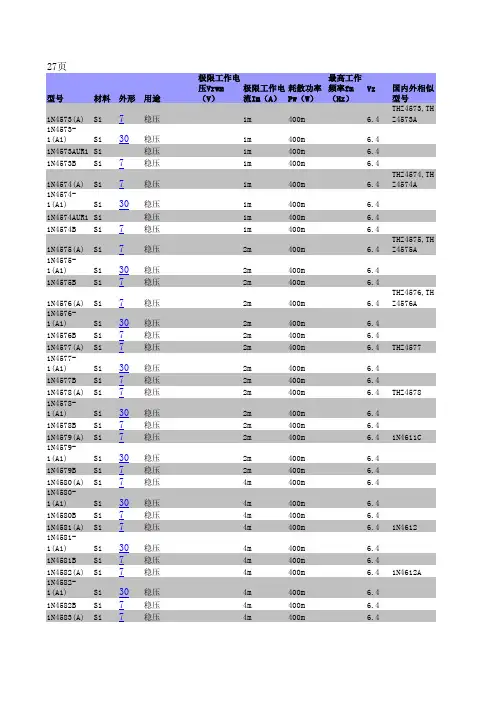


A3361中文资料The A3361x and A3362x Hall-effect switches are extremely temperature-stable and stress-resistant sensors. Superior performance over temperature is made possible through dynamic offset cancellation,which reduces the residual offset voltage normally caused by device overmolding, temperature dependencies, and thermal stress. The two devices differ only in output polarity; the A3361x output current goes low in the presence of a south pole of sufficient strength; the A3362x output current goes high.Each device includes on a single silicon chip a voltage regulator,Hall-voltage generator, small-signal amplifier, chopper stabilization,Schmitt trigger, and a constant-current open-collector output. An on-board regulator permits operation with supply voltages of 3.5 to 24volts. Noise radiation is limited by control of the output current slew rate.Three package styles provide a magnetically optimized package for most applications. Su ffix ‘xLH’ is a miniature low-profile surface-mount package, ‘xLT’ is a miniature SOT-89/TO-243AA transistor package for surface-mount applications; while suffix ‘xUA’ is a three-lead ultra-mini-SIP for through-hole mounting.FEATURESs Internal Current Regulator for 2-Wire Operation s Resistant to Physical Stress s Superior Temperature Stability s Operation From Unregulated Supply s Solid-State Reliability s Small Size Always order by complete part number: the prefix 'A' + the basic four-digitpart number + a suffix to indicate operating temperature range (E) +a two-letter suffix to indicate package style, e.g., A3361ELH .2-WIRE, CHOPPER-STABILIZED,HALL-EFFECT SWITCHES3361 AND 3362Data Sheet 27621.503361 AND 33622-WIRE,CHOPPER-STABILIZED,HALL-EFFECT SWITCHES115 Northeast Cutoff, Box 15036Worcester, Massachusetts 01615-0036 (508) 853-50002Copyright ? 2001 Allegro MicroSystems, Inc.Pinning is shown viewed from branded side.Dwg. PH-003-6S U P P L YG R O U N DN O (I N T E R N A L )C O N N E C T I O NDwg. PH-003-7A S U P P L YG R O U N DG R O U N DSuffix Code 'UA' Pinning(SIP)Suffix Code 'LT' Pinning (SOT-89/TO-243AA)3361 AND 33622-WIRE,CHOPPER-STABILIZED,HALL-EFFECT SWITCHES/doc/1377bc3d67ec102de2bd8931.ht ml3A3361 MAGNETIC CHARACTERISTICS over operating supply voltage and temperature ranges.LimitsCharacteristic Symbol Test Conditions Min.Typ.Max.Units Operate Point B OP B > B OP , I GND = LOW ––125G Release Point B RP B < B RP , I GND = HIGH 40––G HysteresisB hysB OP - B RP5.0–30GA3362 MAGNETIC CHARACTERISTICS over operating supply voltage and temperature ranges.LimitsCharacteristic Symbol Test Conditions Min.Typ.Max.Units Operate Point B OP B > B OP , I GND = HIGH ––125G Release Point B RP B < B RP , I GND = LOW 40––G HysteresisB hysB OP - B RP5.0–30GELECTRICAL CHARACTERISTICS over operating temperature range.LimitsCharacteristic Symbol Test Conditions Min.Typ.Max.Units Supply Voltage V CC Operating3.51224V Output CurrentI GND(L)Output Current Low 5.0– 6.9mA I GND(H)Output Current High12–17mA Chopping Frequency f C –340–kHz Output Settling Time t sd C L = 20 pF ––50μs Output Rise Time t r C L = 20 pF –3.5–μs Output Fall Time t f C L = 20 pF – 3.5–μs Reverse Battery CurrentI CCV RCC = -16 V ––-15mANOTE:Typical Data is at T A = +25°C and V CC = 12 V and is for design information only.3361 AND 33622-WIRE,CHOPPER-STABILIZED,HALL-EFFECT SWITCHES115 Northeast Cutoff, Box 15036Worcester, Massachusetts 01615-0036 (508) 853-5000 4O U T P U T C U R R E N TFLUX DENSITYDwg. GH-007-3+IOUTPUT CHARACTERISTICSA3361xA3362x+B0O U T P U T C U R R E N TFLUX DENSITYDwg. GH-007-4RP B OP B I OUT + I CC I CC +I3361 AND 33622-WIRE,CHOPPER-STABILIZED,HALL-EFFECT SWITCHES/doc/1377bc3d67ec102de2bd8931.ht ml5SENSOR LOCATIONS(±0.005” [0.13 mm] die placement)Package Designator “LH”Package Designators “UA” and "UA-TL"Although sensor location is accurate to three sigma for a particular design, product improvements may result in small changes to sensor location.0.011"0.28 mm NOMDwg. MH-008-8A0.0305"0.775 mm NOMACTIVE AREA DEPTHDwg. MH-011-9BPackage Designator “LT”60040020020601001400AMBIENT TEMPERATURE in °CA L L O W AB L E P AC K A G EP O W E R D I S S I P A T I O N i n M I L L I W A T T SDwg. GH-046-440801201807005003001001603361 AND 33622-WIRE,CHOPPER-STABILIZED,HALL-EFFECT SWITCHES115 Northeast Cutoff, Box 15036Worcester, Massachusetts 01615-0036 (508) 853-50006All Allegro sensors are subjected to stringent qualification requirements prior to being released to production.To become qualified, except for the destructive ESD tests, no failures are permitted.CRITERIA FOR DEVICE QUALIFICATIONQualification Test Test Method and Test Conditions Test Length SamplesComments Biased Humidity (HAST)T A = 130°C, RH = 85%50 hrs 77V CC = V OUT = 5 V High-Temperature JESD22-A108, 408 hrs77V CC = 24 V,Operating Life (HTOL)T A = 150°C, T J = 165°C VOUT = 20 V Accelerated HTOLJESD22-A108,504 hrs 77V CC = 24 V,T A = 175°C, T J = 190°C V OUT = 20 VAutoclave, Unbiased JESD22-A102, Condition C,96 hrs 77T A = 121°C, 15 psig High-Temperature MIL-STD-883, Method 1008,1000 hrs 77(Bake) Storage Life T A = 170°CTemperature CycleMIL-STD-883, Method 1010,500 cycles 77-65°C to +150°C Latch-Up—Pre/Post 6Reading Electro-Thermally—Pre/Post 6Induced Gate Leakage Reading ESD,CDF-AEC-Q100-002Pre/Post x per Test to failure,Human Body Model Reading test All leads > TBDElectrical DistributionsPer Specification—303361 AND 33622-WIRE,CHOPPER-STABILIZED,HALL-EFFECT SWITCHES/doc/1377bc3d67ec102de2bd8931.ht ml7FUNCTIONAL DESCRIPTION+—Dwg. AH-011-2Chopper-Stabilized Technique. The Hall element can be considered as a resistor array similar to a Wheatstone bridge. A large portion of the offset is a result of the mismatching of these resistors. These devices use a proprietary dynamic offset cancellation technique, with an internal high-frequency clock to reduce the residual offset voltage of the Hall element that is normally caused by device overmolding, temperature dependen-cies, and thermal stress. The chopper-stabilizing technique cancels the mismatching of the resistor circuit by changing the direction of the current flowing through the Hall plate using CMOS switches and Hall voltage measurement taps, while maintaing the Hall-voltage signal that is induced by the external magnetic flux. The signal is then captured by a sample-and-hold circuit and further processed using low-offset bipolar circuitry. This technique produces devices that have an extremely stable quiescent Hall output voltage, are immune to thermal stress, and have precise recoverability after temperature cycling. This technique will also slightly degrade the device output repeatability. A relatively high sampling frequency is used in order that faster signals can be processed.More detailed descriptions of the circuit operation can be found in: Technical Paper STP 97-10, Monolithic Magnetic Hall Sensor Using Dynamic Quadrature Offset Cancellation andTechnical Paper STP 99-1, Chopper-Stabilized Amplifiers With A Track-and-Hold Signal Demodulator .Operation. As shown in the output characteristic graphs, the output of the A3362 turns on when a magnetic field (south pole)perpendicular to the Hall sensor is increased above the operate point threshold (B OP ). After turn on, the output will source current equal to the device operating current plus a current source (I GND(H)). When the magnetic field is decreased below the release point (B RP ), the output turns off and will source current equal only to the Hall-effect sensor operating current (I GND(L)). The A3361 output is inverted and the device turns off at B OP and on at B RP . The difference in the magnetic operate and release points is the hysteresis (B hys ) of the device. The hysteresis allows clean switching of the output even in the presence of external mechanical vibration or electrical noise.Applications. It is strongly recommended that an external bypass capacitor be connected (in close proximity to the Hall sensor) between the supply and ground of the device to reduce both external noise and noise generated by the chopper-stabilization technique.Extensive applications information on magnets and Hall-effect sensors is also available in the Allegro Electronic Data Book AMS-702 or Application Note 27701 or/doc/1377bc3d67ec102de2bd8931.ht ml3361 AND 33622-WIRE,CHOPPER-STABILIZED,HALL-EFFECT SWITCHES115 Northeast Cutoff, Box 15036Worcester, Massachusetts 01615-0036 (508) 853-50008PACKAGE DESIGNATOR 'LH'(fits SC-74A solder-pad layout)NOTES: 1.Tolerances on package height and width represent allowable mold offsets. Dimensions given are measured at the widest point (parting line).2.Exact body and lead configuration at vendor’s option within limits shown.3.Height does not include mold gate flash.4.Where no tolerance is specified, dimension is nominal.Dwg. MA-011-3 mmDwg. MA-010-3C in0.00790.00500° GAUGE PLANEDwg. MA-011-3 inDimensions in Inches (for reference only)Dimensions in Millimeters(controlling dimensions)Dwg. MA-010-3C mm0.200.1270° GAUGE PLANE3361 AND 33622-WIRE,CHOPPER-STABILIZED,HALL-EFFECT SWITCHES/doc/1377bc3d67ec102de2bd8931.ht ml90.440.35PACKAGE DESIGNATOR 'LT'(SOT-89/TO-243AA)Dimensions in Inches (for reference only)Dimensions in Millimeters (controlling dimensions)Dwg. MA-012-3 mmPads 1, 2, 3, and B — Low-Stress VersionPads 1, 2, and 3 only — Lowest Stress, But Not Self Aligning NOTE: Exact body and lead configuration at vendor’s option within limits shown.Dwg. MA-012-3 inds 1, 2, 3, and A — Standard SOT-89 Layout ds 1, 2, 3, and B — Low-Stress Versionds 1, 2, and 3 only — Lowest Stress, But Not Self Aligning3361 AND 33622-WIRE,CHOPPER-STABILIZED,HALL-EFFECT SWITCHES115 Northeast Cutoff, Box 15036Worcester, Massachusetts 01615-0036 (508) 853-500010Surface-Mount Lead Form (order A336xEUA-TL)Dimensions in Inches (controlling dimensions)Dimensions in Millimeters(for reference only)PACKAGE DESIGNATOR 'UA'Dwg. MH-014E mm1.27BSC°Dwg. MH-014E in0.050BSC°NOTES: 1.Tolerances on package height and width represent allowable mold offsets. Dimensions given are measured at the widest point (parting line).2.Exact body and lead configuration at vendor’s optionwithin limits shown.3.Height does not include mold gate flash.4.Recommended minimum PWB hole diameter to clear transition area is 0.035” (0.89 mm).5.Where no tolerance is specified, dimension is nominal.3361 AND 33622-WIRE,CHOPPER-STABILIZED,HALL-EFFECT SWITCHES/doc/1377bc3d67ec102de2bd8931.ht ml11The products described herein are manufactured under one or more of the following U.S. patents: 5,045,920; 5,264,783; 5,442,283;5,389,889; 5,581,179; 5,517,112; 5,619,137; 5,621,319; 5,650,719;5,686,894; 5,694,038; 5,729,130; 5,917,320; and other patents pending.Allegro MicroSystems, Inc. reserves the right to make, from time to time, such departures from the detail specifications as may berequired to permit improvements in the performance, reliability, or manufacturability of its products. Before placing an order, the user is cautioned to verify that the information being relied upon is current.Allegro products are not authorized for use as critical components in life-support appliances, devices, or systems without express written approval.The information included herein is believed to be accurate and reliable. However, Allegro MicroSystems, Inc. assumes no responsi-bility for its use; nor for any infringements of patents or other rights of third parties that may result from its use.3361 AND 33622-WIRE,CHOPPER-STABILIZED,HALL-EFFECT SWITCHES115 Northeast Cutoff, Box 15036Worcester, Massachusetts 01615-0036 (508) 853-500012HALL-EFFECT SENSORSPartial Part Avail. Oper.Characteristics at T A = +25°C Number Temp.B OP max B RP min B hys typ Features NotesHALL-EFFECT UNIPOLAR & OMNIPOLAR SWITCHES in order of B OP and B hys 3240E/L +50+5.010chopper stabilized 13209E ±60±5.07.7400 μW, chopper stabilized 3210E ±60±5.07.725 μW, chopper stabilized3361E +125+40 5.0*2-wire, chopper stabilized, inverted output 3362E +125+40 5.0*2-wire, chopper stabilized 3161E +160+30202-wire3141E/L +160+10553235S +175+2515*output 12-25-17515*output 225140E +200+5055300 mA power driver output13142E/L +230+75553143E/L +340+165553144E/L +350+50553122E/L +400+1401053123E/L +440+1801053121 E/L+450+125105HALL-EFFECT LATCHES & BIPOLAR SWITCHES ?in order of B OP and B hys3260E/L +30-3020bipolar switch, chopper stabilized 3425L+30-3019dual bipolar switch, stabilized 13280E/L +40-4045chopper stabilized 3134E/L +50-5027bipolar switch 3133K/L/S +75-7552bipolar switch 3281E/L +90-90100chopper stabilized 3132K/L/S +95-9552bipolar switch 3187E/L +150-150100*3177S +150-1502003195E/L +160-160220active pulldown 13197L +160-16023013175S +170-1702003188E/L +180-180200*3283E/L +180-180300chopper stabilized 3189E/L +230-230100*3275S +250-250100*33185E/L +270-270340*Operating Temperature Ranges:S = -20°C to +85°C, E = -40°C to +85°C, J = -40°C to +115°C, K = -40°C to +125°C, L = -40°C to +150°CNotes 1.Protected.2.Output 1 switches on south pole, output 2 switches on north pole for 2-phase, bifilar-wound, unipolar-driven brushless dc motor control. Outputs may be tied together for omnipolar operation./doc/1377bc3d67ec102de2bd8931.ht ml plementary outputs for 2-phase bifilar-wound, unipolar-driven brushless dc motor control.*Minimum. ? MaximumLatches will not switch on removal of magnetic field; bipolar switches may switch on removal of field but require field reversal for reliable operation over operating temperature range.。
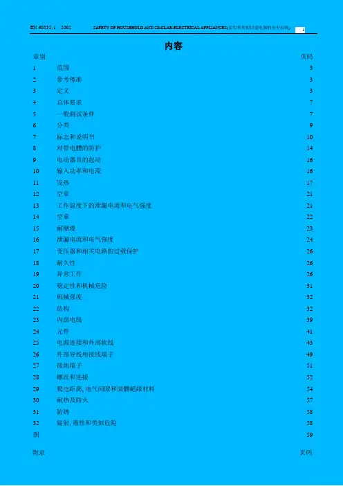
内容章别页码1 范围 32 參考標准 33 定义 34 总体要求75 一般測试条件76 分类97 标志和说明书108 对带电體的防护149 电动器具的起动1610 输入功率和电流1611 发热1712 空章2113 工作温度下的泄漏电流和电气强度2114 空章2215 耐潮湿2316 泄漏电流和电气强度2417 变压器和相关电路的过载保护2618 耐久性2619 异常工作2620 稳定性和机械危险3121 机械强度3222 结构3223 内部电线3924 元件4125 电源连接和外部软线4326 外部导线用接线端子4927 接地端子5128 螺丝和连接5229 爬电距离, 电气间隙和固體絕緣材料5430 耐热及防火5731 防锈5832 辐射, 毒性和类似危险58 图59附录页码A 常規測試69B 由充电电池供电的器具70C 馬達的老化測试72 第一部分:通用要求1范围本标准应用于额定电压不大于250V(单相器具)及额定电压不大于480V(其它器具)的家用及类似用途的电器。
不打算作为一般的家用,但对公众仍可以构成危险的器具,如在商店,照明工业及农场由不熟练人员使用的器具,在本标准的范围之内。
注1:这种器具举例为:工业和商业用途膳食供给设备,清洁器具,以及美容美发器具。
就实际而言,本标准涉及到在住宅内和住宅周围所有人员遇到的由器具所表现出来的共同危险。
本标准一般没考虑:──无人照看的幼儿和残疾人对器具的使用;──幼儿拿器具玩耍的情况。
注2:──对于打算用在车辆、船舶或飞机上的器具,可能需要一些附加要求。
──对于打算用在热带国家的器具,可能需要一些特别要求。
──在许多国家,附加要求由国家卫生保健部门,负责劳动保护的部门,国家供水部门或类似部门来规定。
注3: 本标准不适用于:──专为工业用而设计的器具;──打算使用在经常发生腐蚀性或爆炸性气体(如灰尘、蒸汽或瓦斯气体等)的特殊环境场所的器具;──聲頻﹑視頻及类似電子设备(IEC 65);──医用器具(IEC 601);──手持式电动工具(IEC 745);──个人计算机或类似设备(IEC 850);──便携式电动工具(IEC 1029)。