浮选机液位自动控制系统安装说明书
- 格式:pdf
- 大小:131.67 KB
- 文档页数:9
UQD.Z 型 智 能 浮 球 液 位 变 送 器辽制00000252号1 前言非常感谢您选择丹东通博电器(集团)有限公司的产品。
本产品已通过国家级防爆认证,认证标志:本安型ExiaⅡCT1~T6;隔爆型ExdⅡCT1~T6。
使用前请仔细阅读使用说明书,特别是与防爆相关的环境温度等各项要求。
2 概述a) 本产品执行标准代号:Q/AMM 001-2010浮球液位变送器;b) UQD.Z型智能浮球液位变送器是模拟、数字与微处理器相结合的产品。
该变送器将模拟电压信号转换成4~20mA两线制电流输出信号,并且加载了HART协议通讯。
由于采用了HART总线技术,具有高精度,低漂移,抗干扰能力强等特点,可以实现对仪表的远程组态、监测、维护、及校准等功能,并可构成生产过程测量、监督管理系统。
c) 可广泛适用于粘稠、脏污、易燃易爆及腐蚀性介质以及其它介质液位的测量及液位信号的变送,是石油、化工、冶金、电力及轻工等工业部门生产过程控制中用于液位测量的理想仪表。
d) 型号的组成及其代表意义:3 结构特征与工作原理a)总体结构及工作原理、工作特性:UQD.Z智能浮球液位变送器主要由测量传感机构和智能变送器两大部分组成。
测量传感元件为圆球型浮球。
而变送器则采用平衡杆和平衡锤与浮球构成的力矩平衡机构,因此浮球可以自由地随液位的变化而升降。
根据不同的结构特点分为UQD.Z—90小转角型、UQD.Z—91大转角型、UQD.Z—92外浮球型三种结构,三种规格的电器性能和防爆级别均相同。
变送器具有现代流行壳体设计,造型美观且各工作腔室隔离等特点。
b)主要部件作用及其工作原理:当液位改变时,浮球的位置发生相应的变化,带动主轴转动,主轴与表头(发讯器)角位移传感器输出轴相连接,角位移传感器将浮球随液位的变化转换成相应的电信号,再由浮球控制器内部的电路将此信号转换为与液面变化成正比的标准电流信号。
c)单元结构的联系及工作原理:图 14 主要规格及技术参数4.1 主要参数·电源电压:24V DC;·输出:4~20mA叠加HART通信;·负载电阻:230~1100Ω;·阻尼时间选择:0~32秒;·测量范围:400~1200mm (小转角型);550~1600mm (大转角型) ;·公称压力:≤6.3MPa;·公称通径:DN250·精度等级:1.0级;1.5级·介质密度:≥0.55/cm3;·环境温度:-30℃~70℃;·工作温度:-30℃≤T≤225℃(无散热片);225℃<T≤450℃(带散热片);·法兰标准:HG/T20592-2009、HG/T20615-2009或按用户要求;·电源引入口:M20X1.5(内)或按用户要求;·防护等级:IP67;·诊断功能:仪表故障时,输出报警电流;·组态功能:工程单位、量程、显示、测量类型、介质密度、浮筒高度、报警等组态;·报警功能:可以设置报警上下限。
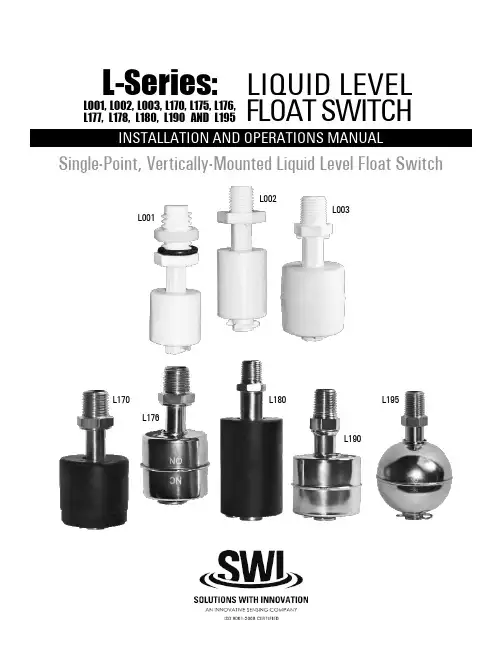
L-Series:LIQUID LEVELFLOAT SWITCHSingle-Point, Vertically-Mounted Liquid Level Float SwitchL001, L002, L003, L170, L175, L176, L177, L178, L180, L190 AND L195L001L002L003L170L176L180L190L1952L-SERIES SINGLE-POINT, VERTICALLY-MOUNTED LIQUID LEVEL FLOAT SWITCHThis manual provides information on the L-Series,Single-Point, Vertically-Mounted Liquid Level Float Switch . It is important that all instructionsare read carefully and followed sequentially. Detailed instructions are included in the Complete Installation section of this manual.Conventions Used in this ManualCertain conventions are used in this manual to convey specific types of information. General technical material, support data and safety information are presented in narrative form. The following styles are used for notes, cautions and warnings:NotesNotes contain information that augments or clarifies an operating step. Notes do not normally contain actions and often follow the procedural steps to which they refer.CautionsCautions alert the technician to special conditions that could injure personnel, damage equipment, or reduce a component’s mechanical integrity. Cautions are also used to alert the technician of unsafe practices, the need for special protective equipment, or specific materials. In this manual, a caution indicates a potentially hazardous situation which, if not avoided, may result in minor to moderate injury.Notice of Copyright and LimitationsCopyright © 2015 Solutions With Innovation, LLC; All rights reserved.Solutions With Innovation reserves the right to make changes to the product described in this manual at any time without notice. Solutions With Innovation makes no warranty with respect to the accuracy of the information in this manual.WarrantyAll Solutions With Innovation Mechanical Level and Flow Controls are warranted free of defects in materials and workmanship for one full year from the date of the original factory shipment. If returned within the warranty period; and, upon factory inspection of the control, the cause of the claim is determined to be covered under the warranty; then, Solutions With Innovation will repair or replace the product at no cost to the purchaser (or owner) other than transportation.Solutions With Innovation shall not be liable for misapplication, labor claims, direct or consequential damage, or expenses arising from the installation or use of the equipment. There are no other warranties expressed or implied, except special written warranties covering specific Solutions With Innovation products.Quality AssuranceThe Quality Assurance System in place at Solutions With Innovation guarantees the highest level of quality throughout the company. Solutions With Innovation is committed to providing full customer satisfaction; both in quality products and in quality service.ContactsPhone: 203-729-6434 Mon-Fri, 9 AM - 5 PM EST Fax: 203-729-0541 for General Inquiries Email:***************************READ THIS MANUAL PRIOR TO INSTALLATION3L-SERIES SINGLE-POINT, VERTICALLY-MOUNTED LIQUID LEVEL FLOAT SWITCHL-Series:LIQUID LEVEL FLOAT SWITCHSingle-Point, Vertical MountTABLE OF CONTENTSL001, L 002, L 003, L 170, L 175, L 176, L177, L178, L180, L190 AND L1951.0 Installation1.1 Unpacking.............................................................................41.2 Before You Begin................................................................4 1.2.1 Site Preparation...........................................................4 1.2.2 Equipment and Tools. (4)1.3 Mounting...............................................................................5 1.3.1 Threaded Mounting. (5)1.4 Wiring....................................................................................52.0 Preventative Maintenance2.1 What To Do..........................................................................6 2.1.1 Inspect Entire Unit Periodically.................................6 2.1.2 Inspect Connections Monthly...................................6 2.1.3 Keep Unit Clean. (6)2.2 What To Avoid.....................................................................63.0 Reference Information3.1 Description...........................................................................73.2 Theory of Operation..........................................................73.3 Troubleshooting...................................................................7 3.3.1 External Causes...........................................................7 3.3.2 Unit Causes. (8)3.4 Agency Approvals................................................................83.5 Specifications........................................................................9 3.5.1 Physical Specifications................................................9 3.5.2 Electrical Specifications..............................................9 3.5.3 Dimensional Specifications......................................103.6 Notes...................................................................................103.7 Model Configurator...........................................................113.8 Replacement Parts. (11)1.0 INSTALLATIONThis section provides detailed procedures on properly installing the L-Series Single-Point, Vertically-Mounted Liquid Level Float Switch.CAUTION! IF THE EQUIPMENT IS USED IN A MANNER NOT SPECIFIED BY THE MANUFACTURER, PROTECTION PROVIDED BY THE EQUIPMENT MAY BE IMPAIRED.1.1 UNPACKINGUnpack the instrument, carefully. Make sure that all components have been removed from the packing material. Inspect all components for damage. Report any concealed damage to the carrier within 24 hours of receiving. Compare the contents with the packing slip and report any discrepancies to the factory immediately. Record the sales order number and/or serial number for future reference when ordering parts.Before Proceeding to Installation, Complete the Following:• Inspect all components for damage. Report any damage to the carrier within 24 hours of receiving.• Record the model and serial numbers for future reference when ordering parts.Model NumberSerial Number1.2 BEFORE YOU BEGINCAUTION! DURING THE INSTALLATION OF THE SINGLE-POINT, VERTICALLY-MOUNTED LIQUID LEVEL SWITCH, THE FLOAT AREA MUST BE KEPT FREE OF METALLIC PARTICLES THAT MIGHT BE ATTRACTED TO THE FLOAT’S INTERNAL MAGNET.1.2.1 Site PreparationEnsure that the length and the inside diameter of the mounting is sized correctly to accommodate the L-Series Single-Point, Vertically-Mounted Liquid Level Float Switch.1.2.2 Equipment and ToolsNo special equipment or tools are required to install the L-Series Single-Point, Vertically-Mounted Liquid Level Float Switch.The Following Are Recommended:• Wrenches, thread sealant, gaskets and/or bolting as required for the process connection.4L-SERIES SINGLE-POINT, VERTICALLY-MOUNTED LIQUID LEVEL FLOAT SWITCH5L-SERIES SINGLE-POINT, VERTICALLY-MOUNTED LIQUID LEVEL FLOAT SWITCH1.3 MOUNTINGThe L-Series Single-Point, Vertically-Mounted Liquid Level Float Switch is available in a variety of threaded mountings. These devices can be installed from the bottom or top of the tank. The switches should be mounted in an area clear of turbulence or direct streams.1.3.1 Threaded MountingHow to Install an L-Series Single-Point, Vertically-Mounted Liquid Level Switch:1 Apply either Teflon ® tape or an appropriate thread sealant to the mounting threads to prevent galling.2 Engage the thread by hand to avoid unnecessary damage.3 Using a wrench, rotate the unit clockwise until it is tight within the mounting.1.4 WIRINGCAUTION! OBSERVE ALL APPLICABLE ELECTRICAL CODES AND PROPER WIRING PROCEDURES.Contact Protection:In order to maintain the life and reliability of the internal reed switch, it is essential to provide protection when switching inductive loads. When the current breaks, the energy stored in the load generates a high frequency voltage across the switch contacts. If the voltage is large enough, it can initiate arcing and cause the contacts to weld together. Damage can ultimately be prevented by suppressing the voltage. Through the use of a diode for DC circuits and a resistor-capacitor network for AC circuits, contact protection willensure reliable performance from the reed switch.TOP MOUNT BOTTOM MOUNTANGLED MOUNT6L-SERIES SINGLE-POINT, VERTICALLY-MOUNTED LIQUID LEVEL FLOAT SWITCH2.0 PREVENTATIVE MAINTENANCEPeriodic inspections are necessary to maintain the proper functionality of the L-Series Single-Point, Vertically-Mounted Liquid Level Switch. The switch is a safety device that protects the equipment it serves. A systematic program of preventative maintenance should be implemented at the time of installation. If the following instructions are completed routinely, the switch will provide continuous, reliable protection.2.1 MAINTENANCE PROCEDURES 2.1.1 Inspect Unit PeriodicallyVerify that there are no cracks or chipped surfaces on the float or stem. Should the unit become damaged, obtain a replacement immediately.2.1.2 Inspect Connections MonthlyL-Series Single-Point, Vertically-Mounted Liquid Level Switches may be vulnerable to excessive heat and moisture. Under these conditions, the electrical wire insulation can periodically break or peel away. As a result, the bare wires may become exposed to the elements and cause damages.• Inspect all wiring, carefully and replace any wires exhibiting signs of brittle insulation.• Inspect all electrical connections to ensure tightness.• Repair or replace any wiring, if necessary.2.1.3 Keep Unit CleanPeriodic cleanings of the float, stem and magnet assembly will ensure the continual, uninterrupted movement of the mechanism. Always keep the open area between the enclosures clean and free of any potential interferences. Objects and debris may cause systematic interruptions and a loss in equipment functionality.2.2 WHAT TO AVOIDNEVER LEAVE THE SWITCH WIRING EXPOSED TO THE ELEMENTS.NEVER PLACE A JUMPER WIRE ACROSS THE TERMINALS TO “CUT-OUT” THE CONTROL. If a jumper is necessaryfor testing purposes, ensure that it is removed prior to placing the control into service.NEVER USE IN SYSTEMS CONTAINING IRON PARTICLES. The magnet within the float assembly can attract the particlesand become jammed.3.0 REFERENCE INFORMATIONThis section illustrates an overview of the L-Series Single-Point, Vertically-Mounted Liquid Level Switch, as well as information on troubleshooting common problems, agency approval listings, and detailed physical, functional and performance specifications.3.1 DESCRIPTIONThe L-Series Single-Point, Vertically-Mounted Liquid Level Switchis a float-actuated device designed to be vertically mounted within atank or process vessel through threaded connections. The low-costswitch is ideal for OEM applications where a single-point high or lowlevel alarm is desired.3.2 THEORY OF OPERATIONThe switching action is achieved through the use of an internalmagnet within the float assembly and its interaction with the switchmechanism. As the liquid level fluctuates inside the tank, the floatfollows. Its magnetic field actuates the switch inside the stem andcloses an electrical circuit.FLOAT SWITCH DIAGRAM3.3 TROUBLESHOOTINGThe L-Series Single-Point, Vertically-Mounted Liquid Level Switch is designed and engineered for trouble-free operation over a wide range of operating conditions. Common problems are discussed in terms of their symptoms and recommended corrective actions.3.3.1 External CausesAn initial indication of improper operation is the failure of the controlled equipment to function (pumps will not start or stop, signal lamps fail to light, etc). If these symptoms occur, whether at the time of installation or during routine service thereafter, check for potential external causes first:• Blown Fuses• Tripped Reset Button(s)• Open Power Switch• Faulty Equipment Controlled By the Level Switch• Defective Wiring to the Level SwitchL-SERIES SINGLE-POINT, VERTICALLY-MOUNTED LIQUID LEVEL FLOAT SWITCH78L-SERIES SINGLE-POINT, VERTICALLY-MOUNTED LIQUID LEVEL FLOAT SWITCH3.3.2 Unit CausesIf a thorough inspection of any external causes fails to locate the problem, proceed to an inspection of the unit, itself.DISCONNECT POWER TO THE LEVEL SWITCH BEFORE PROCEEDING.If you are still in doubt about the condition or performance of your control, consult the factory for further instructions.3.4 AGENCY APPROVALS3.5 SPECIFICATIONS3.5.1 Physical Specifications3.5.2 Electrical SpecificationsL-SERIES SINGLE-POINT, VERTICALLY-MOUNTED LIQUID LEVEL FLOAT SWITCH910L-SERIES SINGLE-POINT, VERTICALLY-MOUNTED LIQUID LEVEL FLOAT SWITCH3.5.3 Dimensional Specifications3.6 NOTESHEX11L-SERIES SINGLE-POINT, VERTICALLY-MOUNTED LIQUID LEVEL FLOAT SWITCH3.7 MODEL CONFIGURATOR3.8 REPLACEMENT PARTSWhen Ordering, Please Specify:• Model & Serial Numbers• Name & Part Number of Replacement Part or AssemblyAll replacement parts are for standard models only. Contact the manufacturer for ordering assistance on all specially modified models (model numbers followed by a “C”; i.e. L003C, L177C, etc.)STEM & SWITCH SUB-ASSEMBLYFLOATCLIPService PolicyOwners of Solutions With Innovation products may request a return of the product, or any part of the product for complete rebuilding or replacement. Units will be rebuilt or replaced promptly. Products returned under the SWI Service Policy must be returned by prepaid transportation. Solutions With Innovation will repair or replace the product at no cost to the purchaser (or owner) other than transportation if:1 Returned within the warranty period; and2 Factory Inspection finds the cause of the claim to be covered under the warranty.If the problem is due to circumstances beyond Solutions With Innovation’s liability, or is NOT covered by the warranty, there will be charges for labor in addition to the parts required to rebuild or replace the equipment.In rare cases, it may be expedient to ship replacement parts; or in extreme cases, an entire product before the damaged product is returned. If a quick replacement service is necessary, notify the manufacturer of the damaged product’s model and serial number. In such cases, credit for the returned materials will be determined on the applicability of the warranty.No claims for misapplication, labor, direct or consequential damage will be allowed.Return Material ProcedureIn order to efficiently process any returned materials, it is essential that a Return Material Authorization (RMA) number be obtained from the manufacturer prior to an item’s return. RMA’s can be issued through local representatives, or by contacting the factory directly. Please supply the following information: 1 The Company’s Name 2 Description of the Material 3 Product Serial Number 4 Reason for Return 5 Product’s ApplicationUsed units must be properly cleaned in accordance with OSHA standards before it is returned to the manufacturer. A Material Safety Data Sheet (MSDS) must accompany units or materials that were used in any type of media. All return shipments to the factory must be by done via prepaid transportation. All product replacements will be shipped F.O.B. manufacturer.BULLETIN: IS-9110.2EFFECTIVE: 1/15。
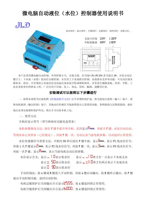
微电脑自动液位(水位)控制器使用说明书本产品采用微电脑自动控制,外形轻便小巧,安装方便,信号线+\P1\P2\P3\多为低压5V,并结合高层楼宇上、下水池(水塔)的水位分级控制,并具有上下水池联合控制,水池排水及多项功能,可自动实现水箱补水、排水、并有效防止水池水位过高溢出或水泵空转或堵转损坏。
非常适合城镇家庭、农村、学校、工况企事业单位的供水工程,广泛应用于印染、化工、食品、饮料、酿酒、制糖等行业。
安装调试可以按照以下步骤进行一、按照本说明书后面的图《控制盒拆开方法》打开本塑料保护盒,将交流电压接到(输入)端子,请将电机接到(输出控制)端子,其他水位传感信号线按照您自己需要的功能,参照接线方法图纸接线。
接好线后必须安装塑料保护外壳,然后才可以给本机上电。
二、使用方法开机时显示型号(型号和相对功能见选型表)电机参数修改方法:按住F 健不放开再开机,直到显示###,再放开F 健,水泵自动启动,等到水泵正常供水(已经稳定),再按F 键一次,自动记录当前电机参数,自动返回正常使用。
水位传感器信号查看方法:开机约50秒后按住F 键不放,显示###,表示P1线水位信号,再接1次F 键显示###,表示P2线水位信号,再按F 键一次,显示###,表示P3线水位信号。
再按一次F 键,显示###,表示当前电机启动后的参数。
水位显示含义:显示表示低水位 显示第2位一点表示下水池无水 显示表示低水位 显示第2位两点表示下水池有水显示表示低水位手动控制法:按A 键或B 键进入手动控制,再按A 键启动输出,按B 键停止输出,按F 键退出手动控制功能,返回自动控制。
电机过载保护后关闭输出并且显示,按A 键退回到正常使用。
电机空载保护后关闭输出并且显示,按A 键退回到正常使用。
直接可控制 220V 1.2KW外配接触器 380V 15KW缺水保护,溢出保护,空载保护,过载保护,堵转保护,故障记忆。
.JLD三、型号和相对功能选型表序号仪表功能开机显示功能作用01计数仪表使用+/P1/P2/P3接线端子计数计算02温控仪表使用+/P1/P2/P3接线端子控制显示温度03三线供水使用+/P1/P2接线端子给水箱、水池、设备供水04三线排水使用+/P1/P2接线端子给水箱、水池、设备排水05五线供水使用+/P1/P2/P3/+接线端子给水箱、水池、供水06防频繁开关使用流量和压力开关组合控制,防止水泵频繁启动07浮球控制使用+/P1/P2接线端子,接上浮球或电触点控制08倒计时定时器设定时间后,倒计时,到达时间后自动停机0924H 定时控制到达设定的时间后,启动水泵,水塔满后自动停机四、接线方法参考接线注意事项:1、输入和输出多是危险电压,请先切断输入电源再接线,以防触电危险。
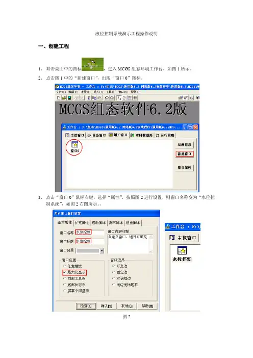
液位控制系统演示工程操作说明一、创建工程1、双击桌面中的图标,进入MCGS组态环境工作台,如图1所示。
2、点击图1中的“新建窗口”,出现“窗口0”图标。
3、点击“窗口0”鼠标右键,选择“属性”,按照图2进行设置,则窗口名称变为“水位控制系统”,如图2右图所示。
图2二、画面设计1、在“水位控制”窗口点击菜单中的【工具箱】图标,单击插入元件按钮,打开【对象元件管理】中的【储藏罐】,选择罐17,点击确定。
如图3所示,则所选中的罐出现在桌面的左上角,用鼠标改变其大小及位置。
图32、按照同样的方法,【储藏罐】选中2个罐(罐17,罐53),【阀】选中2个阀(阀58,阀44),1个泵(泵40)。
按图4放置。
图43、选中工具箱中的【流动快】按钮,单击鼠标并移动光标放置流动快。
如图5所示设置流动快。
图54、选中流动块,点击鼠标右键【属性】,按图6设置属性。
图65、添加文字,选中工具箱中的【标签】按钮,鼠标的光标变为“十字”形,在窗口任意位置拖曳鼠标,拉出一个一定大小的矩形。
建立矩形框后,鼠标在其内闪烁,可直接输入“水位控制系统演示工程”文字。
选中文字,鼠标右键【属性】,按图7设置。
图76、点击菜单中的,可变更字体大小。
按图5添加其他文字。
三、MCGS数据对象设置2、单击工作台【实时数据库】按钮,进入【实时数据库】窗口。
单击窗口右边的【新增对象】按钮,在窗口的数据对象列表中,就会增加新的数据对象。
双击选中对象,按图8设置数据对象属性。
图83、按照图9设置其他数据对象属性。
图94、双击【液位组】,存盘属性按图10设置,组对象成员按图11设置。
图10图11四、动画连接(一)水罐动画连接1、在【用户窗口】中,双击【水位控制】,进入窗口后双击水罐1,弹出【单元属性设置】窗口,如图12所示。
图122、单击【动画连接】,选中折线,则出现。
单击按钮进入【动画组态属性设置】窗口,各项设置如图13所示,单击确认后,水罐1的对象变量连接就成功了。
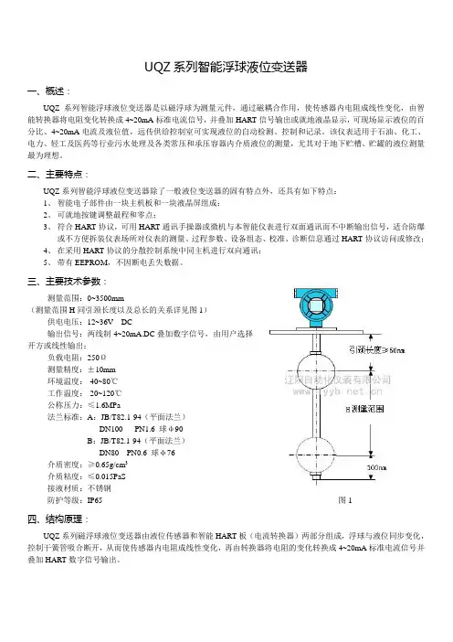
UQZ系列智能浮球液位变送器一、概述:UQZ系列智能浮球液位变送器是以磁浮球为测量元件,通过磁耦合作用,使传感器内电阻成线性变化,由智能转换器将电阻变化转换成4~20mA标准电流信号,并叠加HART信号输出或就地液晶显示,可现场显示液位的百分比、4~20mA电流及液位值,远传供给控制室可实现液位的自动检测、控制和记录。
该仪表适用于石油、化工、电力、轻工及医药等行业污水处理及各类常压和承压容器内介质液位的测量,尤其对于地下贮槽、贮罐的液位测量最为理想。
二、主要特点:UQZ系列智能浮球液位变送器除了一般液位变送器的固有特点外,还具有如下特点:1、智能电子部件由一块主机板和一块液晶屏组成;2、可就地按键调整最程和零点;3、符合HART协议,可用HART通讯手操器或微机与本智能仪表进行双面通讯而不中断输出信号,适合防爆或不方便拆装仪表场所对仪表的测量、过程参数、设备组态、校准、诊断信息通过HART协议访问或修改;4、在采用HART协议的分散控制系统中同主机进行双向通讯;5、带有EEPROM,不因断电丢失数据。
三、主要技术参数:测量范围:0~3500mm(测量范围H同引颈长度以及总长的关系详见图1)供电电压:12~36V DC输出信号:两线制4~20mA.DC叠加数字信号,由用户选择开方或线性输出;负载电阻:250Ω测量精度:±10mm环境温度:-40~80℃工作温度:-20~120℃公称压力:≤1.6MPa法兰标准:A:JB/T82.1-94(平面法兰)DN100 PN1.6 球φ90B:JB/T82.1-94(平面法兰)DN80 PN0.6 球φ76介质密度:≥0.65g/cm3介质粘度:≤0.015PaS接液材质:不锈钢防护等级:IP65图1四、结构原理:UQZ系列磁浮球液位变送器由液位传感器和智能HART板(电流转换器)两部分组成,浮球与液位同步变化,控制干簧管吸合断开,从而使传感器内电阻成线性变化,再由转换器将电阻的变化转换成4~20mA标准电流信号并叠加HART数字信号输出。
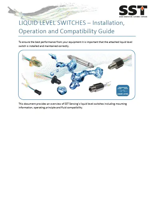
LIQUID LEVEL SWITCHES – Installation, Operation and Compatibility GuideTo ensure the best performance from your equipment it is important that the attached liquid level switch is installed and maintained correctly.This document provides an overview of SST Sensing’s liquid level switches including mounting information, operating principle and fluid compatibility.Contents1 DEFINITIONS ........................................................................................................................... 1-12 TECHNICAL SPECIFICATIONS ................................................................................................... 2-13 INSTALLATION ........................................................................................................................ 3-1 3.1 General Guidelines .......................................................................................................... 3-13.2 Electrical Connections ..................................................................................................... 3-24 OPERATION ............................................................................................................................ 4-1 4.1 Operating Principle Overview .......................................................................................... 4-1 4.2 Fluid Compatibility Guide ................................................................................................ 4-24.3 Test Process .................................................................................................................... 4-45 MAINTENANCE ....................................................................................................................... 5-1 5.1 Cleaning .......................................................................................................................... 5-1 5.2 Disposal .......................................................................................................................... 5-11DEFINITIONSThe following definitions apply to WARNINGS, CAUTIONS and NOTES used throughout this manual.WARNING:The warning symbol is used to indicate instructions that, if they are not followed, can result in minor, serious or even fatal injuries to personnel.CAUTION:The caution symbol is used to indicate instructions that, if they are not followed, can result in damage to the equipment (hardware and/or software), or a system failure occurring.NOTE: Highlights an essential operating procedure, condition or statement.2TECHNICAL SPECIFICATIONSThe following table summarises the key technical specifications. Refer to the appropriate datasheet for more in-depth information (see REFERENCE DOCUMENTS).Switch VoltageRange TemperatureRangeOutputCurrentOutputTypeOutputLogicOptomax Digital 4.5 to 15.4V DC-25 to + 80o Cor-40 to +125o C Up to100mAPush Pull High in AirLow in AirPWMOptomax Industrial 4.5 to 15.4V DCor8 to 30 V DC -25 to + 80o Cor-40 to +125o CUp to1AN-TypeP-TypePush PullHigh in AirLow in AirOptomax Industrial Glass 4.5 to 15.4V DCor8 to 30V DC -40 to +125o C Up to1AN-TypeP-TypePush PullHigh in AirLow in AirLLHP 4.5 to 15.4V DCor10 to 45V DC -25 to + 80o Cor-40 to +125o CUp to800mAN-TypeP-TypePush PullHigh in AirLow in AirPOS 12 to 28V DC-25 to 100o Cor-40 to + 140o C Up to200mAN-TypeP-TypeHigh in AirLow in AirOptomax Basic a 3.3 to 24V DC -25 to + 80o C 4mA Phototransistor outputfor customer tointerface to theirsystemNOTE: If you need a switch other than those listed above, contact SST Sensing; we will be happy to discuss your requirements.a Designed primarily for price sensitive, high volume OEM applications; power supply and microcontroller not supplied with this switch.3INSTALLATIONTo ensure the best performance from your product, it must be installed correctly.3.1General GuidelinesOptical liquid level switches should be mounted from the side or from the bottom for best results.NOTE: Mounting from the top down is not normally advised as false readings can be caused by liquid droplets clinging to the sensing tip. However, if the liquid viscosity is low, then pointing downwards if often fine. Additionally, if the application is a high level alarm and its activation results in the machine shutdown for example, pointing downwards may be acceptable.If you wish to mount in this position, contact SST Sensing to discuss the implications.Avoid mounting positions where ambient light is likely to point directly at the sensing tip, as false readings can occur.Switch performance can be affected by reflective surfaces in front of the sensing tip. ContactSST Sensing if you wish to use a switch within 10mm of a reflective surface (see NOTE).NOTE:If you are installing an LLG switch, avoid reflective surfaces within 50mm of the sensing tip.Figure 3-1 - Example Mounting Positions3.2Electrical ConnectionsCAUTION:•Do NOT immerse the wires in fluid, over time, this will result in irreparable damage to the switch.•Take care when connecting loads. The minimum load impedance should not exceed Vs/max output current. Check the relevant datasheet BEFORE installation.•Shorting the output to Vs or 0V will result in irreparable damage to the switch.•Do NOT install the switch suspended from the cable.•Avoid exerting excessive tensile force on the cable (e.g. tugging).The liquid level switch termination configuration varies depending on the range and selection ordered (refer to the specific datasheet for more detail); in general, connect as follows:Optomax Digital, Industrial and Glass Tip Ranges∙Vs Red∙Output b Green∙0V BlueLLHP Range c∙Vs Red∙Output b Green or white∙0V Blue or blackPOS Range c∙Vs Brown∙Output b Black∙0V BlueOptomax Basic Range∙3-wire versiono LED Anode Redo Output b Greeno0V Blue ∙4-wire versiono LED Anode Redo Output b Greeno0V LED Blueo0V Phototransistor Blackb Refer to the datasheet for output logic details.c Brad Harrison connector available as an alternative to the cable / flying lead options.4OPERATIONOptical liquid level switches do not measure the liquid level, instead they detect the presence or absence of liquid. For an overview of the switches refer to AN-0061, Liquid Level Switches – Selection Guide, more detailed spec information is contained in the switch datasheets; refer to REFERENCE DOCUMENTS for details.4.1Operating Principle OverviewOptical liquid level switches use an infra-red LED and phototransistor accurately positioned at the base of the sensor tip.When the tip is in air, infra-red light reflects internally round the tip to the phototransistor providing strong optical coupling between the two. When the sensor tip is immersed in liquid, the infra-red light escapes from the tip causing a reduction in the amount of light at the phototransistor which makes the output change state.Sensor Tip in Air Sensor Tip Immersed in Liquid4.2Fluid Compatibility GuideThe environment in which the liquid level switch is operating influences the life of the product. To ensure the switch does not fail prematurely, the following material/fluid compatibility should be noted:4.2.1PolysulfoneWhilst the following list may be used as a guide and gives common industrial fluids that are typically acceptable, we recommend that before use you check that the fluid you wish to use this device in is compatible with Polysulfone. Refer to 4.3 Test Process on page 4-4.Acetic acid – GlacialAcetic acid – 10% Ammonia – 88 Ammonium Hydroxide – 10% Ammonium Chloride – 10% Aviation spiritBenzeneBenzoic acidBleachBrineButaneCalcium NitrateCalcium Hypochlorite Carbon Tetrachloride Chromic acidCopper Sulphate CreosoteCyclohexane CyclohexanolDetergent solutionsDiesel fuelDiethylamineDiethyl EtherDioctyl PhthalateEdible fats & oilsEthanol – 50%Ethyl AlcoholEthylene GlycolFerric Chloride FormaldehydeFormic acid GlycerolHeptaneHydrochloric acid – 10% Hydrochloric acid conc. Hydrogen Peroxide IsopropanolIso-OctaneKeroseneLinseed oilMagnesium Sulphate MethanolMotor oilNitric acid 10%Oils - VegetableOxalic acidPetroleum Ether Potassium Hydroxide – 10% Potassium Hydroxide – 50% Silicone fluidsSilver NitrateSoap solutionSodium ChlorideSodium Hydroxide – 10% Sodium Hydroxide – 50% Sulphuric acid – 10% Transformer oil TurpentineVarnishWaterWhite Spirit4.2.2Trogamid®Whilst the following list may be used as a guide and gives common industrial fluids that are typically acceptable, we recommend that before use you check that the fluid you wish to use this device in is compatible with Trogamid® (EU food-contact grade). Refer to 4.3 Test Process on page 4-4.AcetoneBenzeneBreak Free (lubricating oil) Carbon tetrachloride Econa PG32 (Hydraulic fluid) EthanolEthyl acetateEucalyptus oil Formaldehyde solution Glycerine (DAB6)Heating oilIsopropanol MethanolMountain pine oilPetroleum etherPotassium hydroxide (25 w/w-%) Potassium hydroxide (50 w/w-%) Premium gasoline1,2-propane diolRegular gasTest fuel (M15)TolueneXylene4.2.3GlassGlass tipped switches are extremely robust to most chemicals however, chemicals which will attack glass, for example Hydrofluoric acid, are to be avoided. We recommend that before use you check that the fluid you wish to use this device in is compatible with glass. Refer to 4.3 Test Process on page 4-4.4.3Test ProcessThe chemical compatibility lists are not exhaustive and customers often want to use the switches with liquids that have not been approved before. In this case, a compatibility test should be performed using a sensor made with the material (Polysulfone, Trogamid®, glass or stainless steel) you wish to use.The test is simple and is performed as follows:1.Submerge the sensor tip and threads in the liquid of interest. Do NOT submerge the wires.2.Heat the liquid to the maximum expected operating temperature.CAUTION: Assuming it is safe to do so.3.Leave the switch in this liquid at the maximum operating temperature for two weeks.4.Remove the switch and inspect it for signs of:∙Cracking∙Crumbling∙Crazing∙Melting∙Deformation∙SwellingAssuming the switch appears to be unaffected, it should be tested in accordance with its operating procedure to ensure it remains functional.If the switch passes its functional tests, then the liquid can be considered to be compatible with the switch housing material.5MAINTENANCE5.1CleaningIf cleaning of the tip is necessary (i.e., if there is a buildup of algae or other reside), clean the outer surfaces using alcohol based cleaning agents.CAUTION: If your switch is Polysulfone or Trogamid®, do NOT use chlorinated solvents such as tricholoroethane as these are likely to attack the switch material.5.2DisposalLiquid level switches contain electrical components, for this reason they must be disposed of as electrical waste. Please observe your local regulations.Page | 5-1AN-0041 Rev 8 © 2017 SST SENSING LTD.REFERENCE DOCUMENTSRefer also to the following documents for additional information:CAUTIONDo not exceed maximum ratings and ensure sensor(s) are operated in accordance with their requirements.Carefully follow all wiring instructions. Incorrect wiring can cause permanent damage to the device. SST Sensing Ltd recommend using alcohol based cleaning agents. If your switch is Polysulfone or Trogamid®, do NOT use chlorinated solvents such as trichloroethane as these are likely to attack the switch material.Failure to comply with these instructions may result in product damage.INFORMATIONAs customer applications are outside of SST Sensing Ltd.’s control, the information provided is given without legal responsibility. Customers should test under their own conditions to ensure that theequipment is suitable for their intended application. Before use, check that the fluid in which you wish to use these devices is compatible either with Polysulfone, Trogamid®, glass or stainless steel. For technical assistance or advice, please email: ************************SST SENSING LIMITED, 5 HAGMILL CRESCENT, SHAWHEAD INDUSTRIAL ESTATE, COATBRIDGE, UK, ML5 4NS | e: ******************** | t: +44 (0)1236 459 020 | f: +44 (0)1236 459 026。
液位检测系统安装及维护说明结晶器液位检测系统安装及维护说明一.安装注意事项:1.仪表安装必需牢固、可靠、通风好,便于检查、操作、维护。
2.中间接线盒安装在干燥、易检查、环境较好的地方。
3.仪表至接线盒的屏蔽电缆必需单独穿钢管敷设,屏蔽层必须接地。
4.探测器安装要紧固,最好做溢钢防护。
5.由接线盒至探测器的双头铠装电缆要穿钢管敷设,管口至探测器的裸露电缆部分最好用石棉布包好。
电缆两端的快速接头连接必需紧固、可靠、无松动。
如现场蒸汽较大,接头必需做防水处理。
6.安装放射源时,将铯源放置结晶器内时要快速,不易在手上停留时间过长。
如需从结晶器内取出铯源,要将铯源放置专用铅罐内。
二.标定:在更换探测器、铯源棒、结晶器后,确认结晶器通水,必须进行高、低液位标定。
低液位标定方法:先将钢块放入结晶器内,钢块上表面距铜管上口-200 mm处,再按操作箱面板上的“最小液位校验”按钮3秒,指示灯亮后松手,待灯灭后即完成。
高液位标定方法:将钢块放入结晶器内,钢块上表面距铜管上口-50mm处,再按操作箱面板上的“最高液位校验”按钮3秒,指示灯亮后松手。
待灯灭后即完成。
此工作建议在开机前做。
三.维护注意事项:1.定期检查仪表接线端子是否有松动。
2.中间接线盒定期打开检查是否受潮。
3.探测器要轻拿、轻放,避免碰撞损坏。
4.检修时要对电缆接头进行检查,看是否受潮、进水。
铠装电缆接头未跟探测器相连时,务必要包好接头,防止接头进水、损坏。
5.探测器在使用一年后,密封胶有可能老化,建议打开探测器检查后,对原密封处重新密封。
6.出现液位信号或者拉速信号不正常时,首先用万用表测量仪表接受和发出的信号是否正常,其次检查信号电缆是否正常,再次确认PLC或者变频器和液位显示表端的信号是否正常,最后排查信号干扰的可能性。
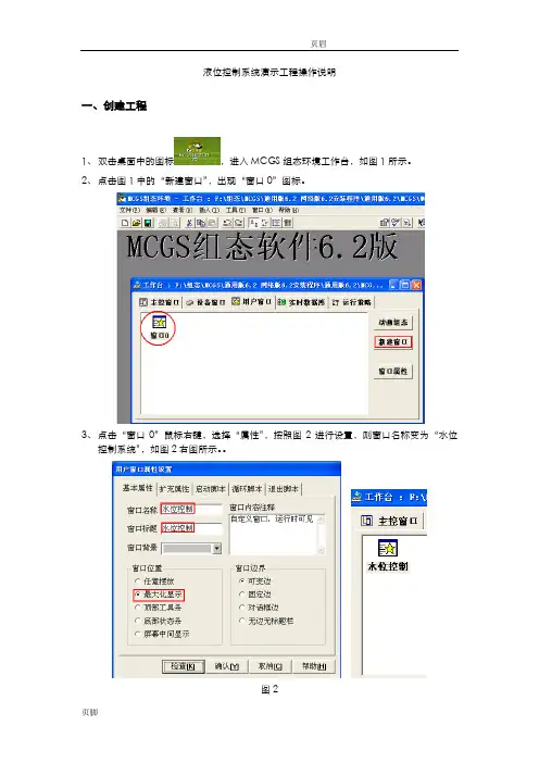
液位控制系统演示工程操作说明一、创建工程1、双击桌面中的图标,进入MCGS组态环境工作台,如图1所示。
2、点击图1中的“新建窗口”,出现“窗口0”图标。
3、点击“窗口0”鼠标右键,选择“属性”,按照图2进行设置,则窗口名称变为“水位控制系统”,如图2右图所示。
图2二、画面设计1、在“水位控制”窗口点击菜单中的【工具箱】图标,单击插入元件按钮,打开【对象元件管理】中的【储藏罐】,选择罐17,点击确定。
如图3所示,则所选中的罐出现在桌面的左上角,用鼠标改变其大小及位置。
图32、按照同样的方法,【储藏罐】选中2个罐(罐17,罐53),【阀】选中2个阀(阀58,阀44),1个泵(泵40)。
按图4放置。
图43、选中工具箱中的【流动快】按钮,单击鼠标并移动光标放置流动快。
如图5所示设置流动快。
图54、选中流动块,点击鼠标右键【属性】,按图6设置属性。
图65、添加文字,选中工具箱中的【标签】按钮,鼠标的光标变为“十字”形,在窗口任意位置拖曳鼠标,拉出一个一定大小的矩形。
建立矩形框后,鼠标在其内闪烁,可直接输入“水位控制系统演示工程”文字。
选中文字,鼠标右键【属性】,按图7设置。
图76、点击菜单中的,可变更字体大小。
按图5添加其他文字。
三、MCGS数据对象设置2、单击工作台【实时数据库】按钮,进入【实时数据库】窗口。
单击窗口右边的【新增对象】按钮,在窗口的数据对象列表中,就会增加新的数据对象。
双击选中对象,按图8设置数据对象属性。
图83、按照图9设置其他数据对象属性。
图94、双击【液位组】,存盘属性按图10设置,组对象成员按图11设置。
图10图11四、动画连接(一)水罐动画连接1、在【用户窗口】中,双击【水位控制】,进入窗口后双击水罐1,弹出【单元属性设置】窗口,如图12所示。
图122、单击【动画连接】,选中折线,则出现。
单击按钮进入【动画组态属性设置】窗口,各项设置如图13所示,单击确认后,水罐1的对象变量连接就成功了。

ZTDDISPLACER LEVEL TRANSMITTERZTD型浮筒液(界)位变送器配DLC3020f液位控制器使用说明书ZTD-DT-JS-1045-2020(WITH DLC3020fLEVEL CONTROLLER感谢您选择丹东通博电器(集团)有限公司的产品。
本使用说明书给您提供有关安装、连接和调试以及针对维护、故障排除和贮存方面的重要信息。
请在安装调试前仔细阅读并将它作为产品的组成部分保存在仪表的近旁,供随时翻阅。
并可通过输入版本号下载本说明书。
如未遵照本说明书进行操作,则本仪表所提供的防护可能会被破坏。
商标、版权和限制说明通博、通博电器、通博泵业、DDTOP、均为公司的注册商标。
本仪表的性能规格自发布之日起生效,如有更改,恕不另行通知。
丹东通博电器(集团)有限公司有权在任何时候对本说明书所述的产品进行修改,恕不另行通知。
质保丹东通博电器(集团)有限公司保证所有刮板流量计自出厂之日起,一年之内无材料和制造工艺方面的缺陷。
在质保期内,如产品出现质量问题而返回,提出的索赔要求经制造厂检验后确定属于质保范围内,则丹东通博电器(集团)有限公司负责免费为买方(或业主)维修或更换。
丹东通博电器(集团)有限公司对因设备使用不当,劳动力索赔、直接或后续损伤以及安装和使用设备所引起的费用概不负责。
除了关于丹东通博电器(集团)有限公司某些产品的特殊书面保修证明,丹东通博电器(集团)有限公司不提供任何明示或暗示的质量保证。
质量丹东通博电器(集团)有限公司通过了ISO9001质量体系认证,产品生产的全过程均严格依照质量体系的规定范围执行,对产品和服务质量提供最强有力的保证。
1安全提示 (4)1.1爆炸可能会导致死亡或严重伤害。
(4)1.2过程泄漏可能导致严重伤害或死亡。
(4)1.3不遵守安全安装准则可能导致死亡或严重受伤。
(4)2产品说明 (4)2.1 产品主要结构 (4)2.2 工作原理 (5)2.3包装 (5)2.4吊装运输时 (5)2.5仓储 (5)3技术特性 (5)3.1主要性能 (5)3.2主要参数 (5)4外形尺寸示意图 (5)5开箱及检查 (6)5.1开箱验货注意事项 (6)5.2检查内容 (7)6安装 (7)6.1安装工具 (7)6.2安装技术要求 (7)6.3 安装操作过程 (8)7调试 (10)7.1调试准备 (10)7.2电气接线 (11)7.3调试操作过程 (12)8注意事项....................................................................................................................................... 错误!未定义书签。
液位自动控制装置摘要本系统采用分布式微机控制系统,通过测量传感器的信号频率来获取液面高度。
系统采用主从式结构,主站和从站都采用以“8051系列单片机+电容式液面高度传感器”模式。
并通过电磁阀来调整液面高度,构成了一个闭环控制系统。
可通过键盘设定所需液面高度,范围为0~25cm,误差不超过±0.3 cm。
并可实时显示当前液位高度和瓶内液体重量以及阀门状态。
当液面超过25cm或液位低于2cm时,可进行声光报警。
主从站之间通过RS232C总线构成串行通讯星型网络。
主站可对8个从站进行定点或巡回监测,查询各从站的实时状态,并可显示其从站传输过来的从站号和液位讯息,并可控制从站液位。
并且在巡回检测时,主站能任意设定要查询的从站数量、从站号和各从站的液位讯息。
当收到从站发来的报警信号后,能声光报警并显示相应的从站号,可自动调整从站液位为20cm。
从站能够输出从站号、液位讯息和报警信号,并且能对主站设定的液位控制信息相应。
该系统布局合理,运行平稳,控制精度较高,完全达到了题目基本部分的要求,并基本实现了发挥部分要求。
一、总体方案的设计1、主站的整体设计:以单片机为控制核心,通过液位传感器实时获取储液瓶B的液面高度,并通过显示器实时显示液面高度、重量。
当键盘有输入时,单片机根据键盘输入的功能要求,单片机通过控制电磁阀1、2来提升或降低液面高度达到设定值,根据题意整体规划主站的系统如图(1)图(1)2、主站和从站整体设计主从站之间通过RS232C总线构成串行通讯网络,主站定期查询液面信息,并对液面信息进行控制。
主机处理器GND RXD TXDGND TXD RXD1号从机GND TXD RXD2号从机GND TXD RXD8号从机图(2)二、系统模块的确定和设计分析题目要求,系统为一个主从式测控系统。
由通讯网络把主站和多个从站连成一个系统。
通讯网络可采用RS232C等接口组成。
液位监测与控制装置的功能可有多种方案实现,但一般都都由控制单元、执行机构和检测单元单元三部分组成。
液位控制器安装调试指南说明书1. 概述液位控制器是现代化工、石油、水处理等行业中常用的自动化设备,用于监测和控制液体容器中的液位。
本指南旨在提供液位控制器的安装和调试步骤,以确保设备正常运行并满足用户需求。
2. 安装准备在开始安装液位控制器之前,请确保以下准备工作已完成:2.1 确定安装位置:选择合适的安装位置,应考虑液位控制器与液体容器之间的距离、外部环境温度、防爆要求等因素。
2.2 检查设备完整性:检查液位控制器的包装是否完好,设备是否缺损或损坏。
2.3 准备所需工具:根据液位控制器的安装需求,准备好相应的工具,如扳手、螺丝刀等。
3. 安装步骤请按照以下步骤进行液位控制器的安装:3.1 关闭电源:在安装之前,确保所有电源已经关闭,以免发生触电危险。
3.2 连接电源线:按照液位控制器的接线图或说明书,将电源线正确地连接到液位控制器上。
3.3 安装传感器:根据液位控制器的型号和设计,选择合适的传感器并按照说明书的要求进行安装。
确保传感器与液体容器的接触牢固可靠。
3.4 连接信号线:根据液位控制器的要求,连接信号线到液位控制器的输入端口。
注意线缆的接线是否正确、牢固可靠。
3.5 安装外壳:将液位控制器的外壳安装在合适的位置,并固定好螺丝。
确保外壳完整、牢固。
4. 调试步骤完成液位控制器的安装后,进行以下调试步骤,以确保设备运行正常:4.1 检查电源:打开电源,检查液位控制器的工作指示灯是否亮起,以确认电源连接正常。
4.2 参数设置:根据液体容器的需求,设置液位控制器的相关参数,如液位上下限、报警阈值等。
确保参数正确、合理。
4.3 信号测试:通过向液体容器中注入或排出液体,测试液位控制器的信号输出是否准确。
可以通过使用万用表或示波器进行信号检测。
4.4 报警测试:模拟报警条件,如高液位报警、低液位报警等,测试液位控制器的报警功能是否正常,确保及时准确地发出报警信号。
4.5 数据记录:在调试过程中,记录液位控制器的相关参数和测试结果,以备后续分析和维护。
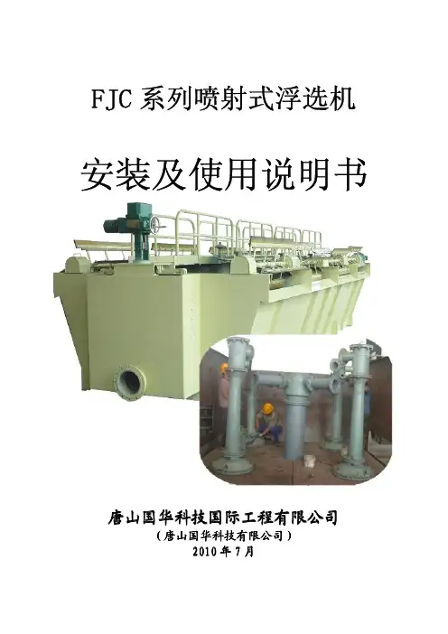
目录1. 前言 (3)2. 浮选机及工作过程描述 (3)3. 浮选机工作原理 (4)4. 技术数据 (5)4.1 XCFⅡ和KYFⅡ浮选机作业机组 (5)4.2 给矿箱 (6)4.3 浮选机 (6)4.3.1 驱动机构 (6)4.3.2 搅拌机构 (7)4.3.3 槽体 (7)4.4中间箱和尾矿箱 (7)4.5 泡沫刮板 (8)5. 仪表 (8)5.l 总论 (8)5.2矿浆液位自动控制 (9)5.3充气量自动控制 (10)5.4仪表的安装、操作、维护(详见各仪表说明书) (10)6. 安装指南 (10)6.1 概述 (10)6.1.1 到货后验收 (11)6.1.2 安装前须知 (11)6.1.3 贮存 (11)6.2 安装指南 (11)6.2.1 地基检查 (11)6.2.2 槽体安装 (11)6.2.3 定子 (12)6.2.4 主轴部件 (12)6.2.5 电机装置 (12)6.2.6 刮板及刮板电机装置 (12)6.2.7 中、尾矿阀门装置 (12)6.3 安装检查 (12)7. 试车指南 (13)7.1试车前准备 (13)7.2 空槽试车 (13)7.3 充水试验 (13)7.4 给矿浆试运转 (14)8. 操作指南 (14)8.l 概述 (14)8.2 空槽起动 (14)8.3 停机 (14)8.3.1 浮选槽排空后停机顺序 (14)8.3.2 保持满槽矿浆停机 (14)8.4 停机后满槽起动 (15)8.5电源事故处理 (15)8.6风量调节 (15)9.维修指南 (16)9.1生产中的维护 (16)9.2计划检修中的维修 (16)9.2.l投产3-6个月期间停机检查 (16)9.2.2计划检修 (17)9.3润滑指南 (17)1. 前言本手册介绍了XCFⅡ和KYFⅡ型浮选机,特别是XCFⅡ-8和KYFⅡ-8浮选机的一般情况及设备数据。
对XCFⅡ/KYFⅡ型浮选机的安装、操作、维护程序作了描述。
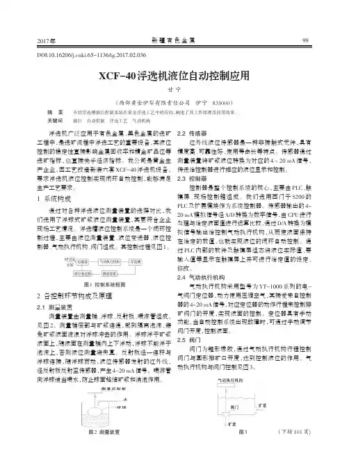
浮选机液位自动控制系统安装说明书北 京 矿 冶 研 究 总 院目录1系统组成............................................................................................................1-1 2安装条件............................................................................................................2-2 2.1供电要求.....................................................................................................2-2 2.2供气要求.....................................................................................................2-2 2.3供水要求.....................................................................................................2-2 3安装步骤及要求................................................................................................3-2 3.1液位测量装置安装.....................................................................................3-2 3.2气动调节阀的安装.....................................................................................3-3 3.3仪表箱安装.................................................................................................3-5 3.4系统电气接线要求及注意事项.................................................................3-6 3.5系统气源、水源安装注意事项.................................................................3-61 系统组成浮选机液位自动控制系统如图1所示,由液位测量装置、液位控制器和气动调节阀组成,液位控制器以液位测量装置传入的液位测量值与操作人员的液位设定值为依据,对液位气动调节阀进行控制,从而实现液位的自动调节;电动调节阀控制系统由电动执行机构、锥阀、控制部分组成,该系统为液位自动控制系统的辅助系统,当液位自动控制系统进行维护或出现故障时,可使用电动调节阀控制系统进行手动控制中(尾)矿箱的排矿量。
矿浆图1.浮选机液位自动控制系统示意图其中,液位测量装置是由激光液位计、液位计支架、浮球、连杆、反射盘、冲水管等部件组成,将液位值以4~20mA信号送出;控制器安装在仪表箱内,接收液位计传入的输入信号,并根据使用人员输入的设定值输出控制信号;气动调节阀包括气动执行机构、锥阀和连杆。
2 安装条件2.1供电要求1. 负荷类型:重要连续生产负荷2. 电源:1)仪表专用AV 220V±10%,频率50Hz±1Hz;2)AV380V,额定功率550W3. 功耗:每套系统总耗电量1500W2.2供气要求1. 气源位置:在每台气动阀门执行机构附近,距离不超过1米2. 气源工作压力:500KPa3. 耗气量: 3600l/h (每台气动执行机构)4. 气源温度: 净化干气在工作压力下应比环境温度下限至少低10℃5. 含油量:不大于8mg/m36. 含尘量:0.1g/m3, 粒度不大于10um7. 供气配管:DN15镀锌管,配不锈钢球阀(DN15)。
2.3供水要求1. 供水压力: 20KPa2. 供水流量: 3m3/h3. 在矿浆液位测量装置旁提供清水源,用于安装液位计冲洗管。
3安装步骤及要求3.1液位测量装置安装液位测量装置采用激光液位计作为液位检测和变送元件,利用浮球间接测量浮选机的矿浆液位。
液位测量装置的安装配合浮选机安装同时进行,结构如图1所示,其在浮选机上的位置参见《液位测量装置安装图》。
安装注意事项:1.将液位不锈钢测量筒的法兰与浮选机的浮选机隔离管法兰,用6-M12螺栓连接。
注意保护浮球和浮球杆。
2.将浮球到反射盘的距离调至1.6米;3.液位计接线为10米,在测量筒上的保护罩内;3.2气动调节阀的安装浮选机液位气动调节阀包括:QL200型浮选机用气动执行机构和锥阀两部分,锥阀阀杆与执行机构通过连接头连接。
气动执行机构是由双作用气缸和YT-1000R型定位器连接组成的直行程气动执行机构,可带手操机构,它以压缩空气为动力,接受调节单元或人工给定的4-20mA直流电信号,转变成与之相对应的直线位移,以调节矿浆流量,控制浮选槽液位。
3.2.1 气动执行机构的结构执行机构主要部件是:YT-1000R定位器、气缸、支架、摆臂、滑板及手操机构等组成(如图1),其材料采用优质碳结钢和灰铸铁,气缸活塞采用两个L型密封件双向密封,效果好寿命长。
图11-弹簧2-芯杆3-螺杆4-手轮5-手轮螺芯 6-盖母7-板 8-连接座9-立柱10-滑板11-摆臂 12-定位器13-上缸盖 14-球阀 1 5-拉杆16-活塞 17-缸筒 18-活塞杆 19-下缸盖20-套筒 21-过滤减压阀3.2.2 安装步骤及要求1.气动执行机构直立安装于浮选机中(尾)矿箱上。
具体位置参照《液位控制系统气动调节阀安装图》。
2.安装应该首先调整中(尾)矿箱中锥阀杆,使锥阀的位置正好将阀下的圆孔完全堵住,以保证使用时不会有泄漏现象;锥阀调好后,使锥阀杆保持在垂直状态。
3.气动执行机构(气缸)安装的中(尾)矿箱上已经有安装孔,但应该根据具体情况进行调整,保证气动执行机构的活塞杆与中(尾)矿箱中的锥阀杆同轴。
4.气动执行机构的活塞杆与中(尾)矿箱中的锥阀杆的相对位置已经基本确定,连接采用连接头式,可以直接安装,但在锥阀杆上还有一个销钉可以调整阀杆的上下位置,清水试车时可以通过清水试验阀门是否有泄漏现象,若有的话,可以检查锥阀阀杆销钉的位置是否合适,给与适当调整。
5.气动执行机构的气缸通过其底部的四个螺栓直立安装于中(尾)矿箱上面,要保证垂直、稳定,不平处用垫片调整。
6.安装完成后要手动调整阀门,要求手轮能自如调整阀门的开关,若不能,需要重新调整阀门的安装!7.气动执行机构的接线要求使用2×0.75 RVVP电缆,根据接线图接线,电缆使用镀锌管做穿线管。
8.安装过程注意定位器、过滤减压阀等配件的保护,以防损坏。
9.气动执行机构配有安装附件:PVC塑料管一根、紫铜管两个(每个3 cm长)、气管接头两个、G1/2—G1/4变径接头一个。
其安装方法是:1、将紫铜管插入塑料管两端,再将塑料管两端插入气管接头。
2、带气管接头的塑料管两端分别与气动执行机构的过滤减压阀进气口和气源端连接;连接时用到的气管接头和变径要求使用生料带,注意连接紧密,防止泄露。
3、气动执行机构的气源与过滤减压阀连接前,要求将管路中的灰尘和杂物先吹干净,以防灰尘杂物进入执行机构!10.在后续的使用过程中应该经常检查过滤阀内是否有积存的杂质,应经常清理以保证气源质量!若中途停产时间较长,在使用之前应断开气源管与气动执行机构的连接,吹出气源管中杂质!11.若有不清楚的地方,请及时与北京矿冶研究总院自动化所联系。
3.3仪表箱安装液位仪表箱安装在浮选机上或过道上,原则是距液位测量装置就近安装。
参见《液位仪表箱安装图》。
安装要求如下:1、要求安装位置便于操作人员操作;2、仪表箱支架焊接在浮选平台上,与仪表箱螺栓连接,要安装牢固;3、在没有电气专业技术人员的情况下不能随意接通仪表箱电源,更不能上电调试设备;3.4 系统电气接线要求及注意事项1、系统电源按前述要求配备,直接进入仪表箱内的端子和空开上;2、参照系统布线图《A07B07C01D10C2-系统布线示意图》安装电缆保护管(穿线管);3、液位测量装置与仪表箱之间一根穿线管,穿3×0.75 RVVP电缆,该电缆由液位计自备,长10米;4、液位气动执行机构与仪表箱之间一根穿线管,穿2×0.75 RVVP电缆;5、电动阀与仪表箱之间需要3根线:一根3×1RVV电源线、一根3×0.75 RVV电缆和一根3×0.75 RVV电缆。
三根电缆使用两根穿线管,一根穿电源线和控制线;另一根穿信号线;6、穿线管使用镀锌钢管,规格DN20,为方便穿线,可以用更大管径的;7、参照《A07B07C01D11C2-仪表箱端子接线图》接线,要求上端子的电缆加接线柱;3.5系统气源、水源安装注意事项1、系统气源用于供给气动执行机构使用,参照前述气源要求和气动执行机构安装要求中的内容进行安装;2、气源主管路气管采用DN25钢管,分管为DN15即可;具体管路布置由安装方和业主自行决定;3、安装完成后需要通气试验,检查是否有漏气现象;4、系统水源用于供给液位测量装置,主要用于冲洗浮球和消除隔离筒中的泡沫,参照前述水源要求安装;5、水源管路布置由安装方与业主自行确定,与系统自带的手阀连接;以上安装要求和注意事项有不清楚的地方,请及时与北京矿冶研究总院自动化所联系。