
WIT-18R-M-XL中文资料
- 格式:pdf
- 大小:52.21 KB
- 文档页数:2

M-Track FeaturesLight Duty ActuatorsIntegral end of stroke limit switches standard. No clutch required.Integrated rear clevis for easy pin-to-pin mountingThermal overloads in windings protect the motorOptional potentiometer assures accurate, consistent positioning feedbackKey Features• Compact size • Efficient design• Easy to use and installDual quad ring bearing provides double protection and rod supportLightweight aluminum extension rodCompact spur gear design allows compact space requirementsStandard ModelsM1Unique Hi-Load solid thrust ringSealed limit switchesIP69K and Temporary ImmersionNeoprene Sealing Boot available upon request.Please see pages 9 & 10 for dimensional information. Consult factory for ordering details.M-Track Configurator How To SelectStep 1 – Determine Load and Stroke length requirementsUse the Quick Selection guide to identify the model that will provide the load capacity and stroke length needed for your application.Step 2 – Identify motor type and voltageSelect DC motor and motor voltage.Step 3 – Confirm Speed and Current draw requirements Using the charts provided, confirm that unit speed and current draw is appropriate for the intended use.Step 4 – Confirm the application Duty CycleAt full load capacity, actuators have a 25% duty cycle.Duty cycle is the amount of on-timeon-time + off-timeA unit that runs for 15 seconds should be off for 45 seconds.Side loading and shock loads must be considered in actuator applications. Side loading and cantilevered mounting should be eliminated through proper machine design. Side loading will dramatically reduce unit life. While actuators can withstand limited shock loads, it is recommended that shock loading be avoided wherever possible. (See General Mounting Information on page 71)Step 5 – Unit OptionsM-Track units include end-of-travel limit switches as a standard feature. For positional feedback, a 12K linear membrane potentiometer can be factory installed. The changing potentiometer value provides unit movement feedback for units that are not visible to the machine operator.Scan to watch!Linear Actuator Basic Selection Video https:///ydtpk6M-Track 1DC Motor Acme ScrewUp to 165 lb. (734 N) Rated LoadUp to 1.75 in. (45 mm)/sec. Travel SpeedM-Track 1 compact units are completely self-contained and sealed to allow use in small spaces without sacrificing power or capability. The load and length capabilities provide solutions for a diverse range of intermittent duty applications.Functionally, M-Track 1 actuators are easily interchanged with comparable size hydraulic or pneumatic cylinders on intermittent duty applications. The actuator provides consistent, repeatableperformance even for applications with operating conditions including temperature extremes, high humidity, or significant dust.Features• An Acme Screw drive delivers up to 165 pounds (734 N) of force at a minimum extension rate of 0.25 inches (6.35 millimeters) per second.• The anodized aluminum alloy housing resists corrosion and provides protection from dirt, dust and humidity.• Temperature operating range of –20º F to +150º F (-26º to +65º C). –40º F to +185º F (-40º to +80º C) available.• Standard stroke lengths of 1, 2, 4, 6, 8, 10, 12 inches (50, 100, 150, 200, 254, 300 millimeters) are available.• Internal limit switches automatically shut off the unit at end of stroke.• Optional potentiometercan provide positional location feedback.• IP69K Static, IP65 Dynamic• Temporary Immersion with protective boot (see page 10).• Rod is non rotating during operation, can be rotated for mounting purposes.Typical ApplicationsLight load and short distance applications such as:• Valve and vent adjustments • Light weight tilt or lift positioning • Vise and clamp operations.65Ø.785-.002+.00019.94-0.0510Ø.259.2536.586.43.259.253355[ ][ ]M-Track 1• Stroke and its tolerance are based on a unit with no attached load operating at rated voltage +/-.5VDC, 70° F controlled temperature environment. Note normal wear,temperature changes and load variations all affect the stroke tolerance. If stroke tolerance is critical it is advisable that the selected unit be evaluated for performance in the specific application.• The retract pin to pin dimension and its tolerance are based on a unit with no attached load operating at rated voltage +/-.5VDC, 70° F controlled temperature environment. Note normal unit wear, temperature changes and load variations all affect the stroke tolerance. If the retract pin to pin dimension is critical it is advisable that the selected unit be evaluated for performance in the specific application. • Rotation of the extension tube is allowed up to one full turn to aid mounting. Rotate rod clockwise until it is fully seated in the unit. Rotate counterclockwise no more than one full turn to align clevis pins.• Mounting points in the application must allow the actuator to reach full-extend and full-retract to ensure the internal limit switches are activated. If this is not possible another method for shutting off the actuator must be employed.• If the actuator encounters an obstruction at mid-stroke and is not allowed to reach the internal limit switches the actuator will stall. An internal thermal circuit breaker isdesigned to protect the motor from damage during stalling and/or overheating due to exceeding duty cycle. If tripped it will self reset after a short period of time. The thermal is rated to protect the motor in the event of a stall condition. It is not designed to protect any other device in the circuit. • Warner Linear recommends an externally mounted fuse of 6 AMPs max for 12VDC and 3 AMPs max for 24VDC circuit protection. Anything connected to the actuator must be sized to withstand the actuator’s power consumption orindependently isolated from the circuit.8911773 BODY6294511 TERMINALS (2)TO EXTEND ACTUATORNO CONNECTOR ON POTENTIOMETER UNIT["A"]THRU ALL DIMENSIONS ARE NOMINALUNLESS OTHERWISE SPECIFIEDMeasurements in inches, metric in brackets.。
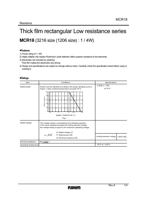
ResistorsRev.A 1/4Thick film rectangular Low resistance seriesMCR18 (3216 size (1206 size) : 1 / 4W)z Features1) Power rating of 1 / 4W2) Highly reliable chip resistor Ruthenium oxide dielectric offers superior resistance to the elements. 3) Electrodes not corroded by solderingThick film makes the electrodes very strong.4) Design and specifications are subject to change without notice. Carefully check the specification sheet before using or ordering it.z Ratings0.25W (1 / 4W)−55°C to +155°C1.58V(10Ω)at 70°CItemConditionsSpecificationsRated powerRated voltageOperating temperatureNominal resistance See Table 1.Limiting element voltage Power must be derated according to the power derating curve in Figure 1 when ambient temperature exceeds 70°C .The voltage rating is calculated by the following equation. If the value obtained exceeds the limiting element voltage, the voltage rating is equal to the maximum operating voltage.E: Rated voltage (V)P: Rated power (W)R: Nominal resistance (Ω)E = P ×R20406080100−55070100155AMBIENT TEMPERAT URE (°C)P O W E R L O A D (%)Fig.1ResistorsRev.A 2/4F (±1%)J (±5%)0.15≤ R ≤ 9.1(E24)(E24)(E24)(E24)±2500.1≤ R ≤ 0.13(E24)400±2000.047 ≤ R ≤ 0.091(E24)500±3000.1 ≤ R ≤ 0.13400±2000.15 ≤ R < 0.91±250500±3000.047 ≤ R ≤ 0.091Table 1Resistance tolerance Resistance range(Ω)Special specificationL L SL L SResistance temperature coefficient(ppm/°C)z Before using components in circuits where they will be exposed to transients such as pulse loads (short–duration, high–level loads), be certain to evaluate thecomponent in the mounted state. In addition, the reliability and performance of this component cannot be guaranteed if it is used with a steady state voltage that is greater than its rated voltage.z CharacteristicsResistorsRev.A 3/4z Dimensions (Unit : mm)z PackagingResistorsRev.A 4/4z Part No. ExplanationSpecial part numberPart No.M C 1R Nominal resistance8E Z HJ LResistance tolerance ±1%±5%F J10Ω or less (class F)1Ω or less (class J)0.1Ω or lessL SReel (φ180) : JEITA ET-7200B: Standard productFL,FS,JSJL :: 4 digits 3 digitsResistance code, 3 or 4 digits.Resistancetolerance+Special P/NResistance codeAppendixAbout Export Control Order in JapanProducts described herein are the objects of controlled goods in Annex 1 (Item 16) of Export T rade ControlOrder in Japan.In case of export from Japan, please confirm if it applies to "objective" criteria or an "informed" (by MITI clause)on the basis of "catch all controls for Non-Proliferation of Weapons of Mass Destruction.Appendix1-Rev1.1。

18" Powered Subwoofer with KLARK TEKNIK DSP Technology and ULTRANET Networking TBV118L-AN##Front loaded powered subwooferfor touring, portable andinstallation applications##3,000 Watt power featuring KLARK TEKNIK Class-D technology ##KLARK TEKNIK Digital Signal Processing for total system control ##ULTRANET digital audio networking connects to mixers and other sources##Carbon fibre loaded 18" neodymium low frequency driver##Dual voice coil design forhigh power capacity and extended low frequency output##Fully featured user interface with LCD display for ease of navigation ##PC remote control software downloadable at ##Low distortion bass reflexport design##18 mm (3/4") plywood enclosure with hard wearing semi matt black paint finish##Integral suspension hardwarefor efficient array configuration and aiming##Multiple M10 mount points allow eyebolt suspension in any orientation ##Rugged powder coated perforated steel mesh grille##20 mm threaded pole mount to support satellite speaker##Durable handles foreasy lifting and carrying The TBV118L-AN is a compactpowered single 18" 3,000-Wattfront-loaded subwoofer that is ideallysuited for a broad range of speechand music sound reinforcementapplications in both fixed, portableand touring audio systems.Designed to work individuallywithout a controller, the TBV118L-ANprovides optimal performancefor FOH, offstage fill, stereo in-fill ordistributed fill applications in a wide range of venues including nightclubs, concert halls, houses of worship, and more.Custom-Engineered DriversTURBOSOUND is recognised the world overfor designing and building some of the mosticonic loudspeakers and subwoofers. We takemeticulous care and pride in maintainingthat reputation by utilising only driversdesigned specifically for each application –it’s what sets us apart from the competition.The TBV118L-AN features a carbon fibreloaded 18" neodymium low frequency driverthat utilises a dual voice coil design for highpower capacity and extended low frequencyoutput. For its size and operating bandwidth,the TBV118L-AN delivers extremely high andvirtually distortion-free output for world-classlow frequency performance that will standthe test of time.18" Powered Subwoofer with KLARK TEKNIK DSP Technology and ULTRANET Networking TBV118L-AN##Mains input and link output onNeutrik powerCON* connectors##3-Year Warranty Program*##Designed and engineered in the U.K.*All third-party trademarks are the property of their respective owners. Their use neither constitutes a claim of the trademark nor affiliationof the trademark owners with MUSIC Group. Product names are Class-D – Massive Power,Perfect SoundEquipped with a very efficient and lightweightKL ARK TEKNIK Class-D power amplifier, theTBV118-AN provides an impressive 3,000Watts of output power in a highly portable andlightweight package. Class-D amplificationmakes all the difference, offering the ultimatein energy efficiency and eliminating the needfor heavy power supplies and large heat sinks.Onboard DSPA high degree of control over the loudspeakersystem's performance is managed by asophisticated, but easy to use KL ARK TEKNIKDigital Signal Processor (DSP), which providesdynamic EQ and transparent limiting forthe utmost punch and definition at highoutput levels – and long-term reliability.18" Powered Subwoofer withKLARK TEKNIK DSP Technology and ULTRANET NetworkingTBV118L-ANULTRANET ConnectivityULTRANET connectivity is provided by two locking etherCON* connectors. Up to 16 independent channels of 24-bit digital audio and control data are transmitted via a single CAT5 cable between compatible digital devices – including mixers, I/O stage boxes, powered loudspeakers and personal monitoring systems. Simplified cable routing and ease of setup translate directly into significant time saved during installation.Intuitive User InterfaceOn the rear panel of the amplifier module, the user interface's LCD display and single rotary encoder provide intuitive access to: position compensation, user EQ control, subwoofer integration and signal routing features. In addition to the balanced XLR input, an XLR output is provided for daisy-chaining more active subwoofers or for use with active loudspeakers. An onboard USB port provides access for remote control of the TBV118L -AN via a free PC computer software download from – as well as convenient DSP firmware updates.Front Loaded Enclosure DesignFront loaded enclosures provide an optimal combination of low frequency extension, bass articulation and temporal accuracy for high impact sound reinforcement applications. The low distortion bass reflex port design utilised in the TBV118L-AN reinforces the bass musical instrument frequencies and on board DSP processing ensures an effective acoustic transition for use with TBV123-AN active line array elements. For low-frequency bass extension, the recommended cabinet ratio consists of one TBV118L-AN subwoofer per 3 TBV123-AN elements. For reverse cardioid subwoofer configurations, multiples of three TBV118L-AN enclosures are recommended with two front-firing enclosures and one rear-firing enclosure.18" Powered Subwoofer withKLARK TEKNIK DSP Technology and ULTRANET NetworkingTBV118L-ANPlywood ConstructionFinished in a highly durable semi matt black paint, the cabinet is constructed from 18 mm (3/4") plywood with a rugged powder coated perforated steel mesh grille backed with reticulated foam, a 20 mm threaded pole mount to support satellite speakers, and a durable handle for easy transport. The TBV118L-AN includes integral suspension hardware for efficient array configuration and aiming, plus multiple internal M10 mount points that allow eyebolt suspension in any orientation.Mains input and output link power connectors are Neutrik powerCON.Acoustic Simulation ToolsEASE GLL files are provided for EASE Focus Acoustic Simulation Software, which is available for free download. This allows accurate calculation of both acoustic coverage and suspension pick point selection for tilting and aiming the array at the desired angle.18" Powered Subwoofer with KLARK TEKNIK DSP Technology and ULTRANET Networking TBV118L-ANYou Are CoveredWe always strive to provide the best possible Customer Experience. Our products are made in our own MUSIC Group factory using state-of-the-art automation, enhanced production workflows and quality assurance labs with the most sophisticated test equipment available in the world. As a result, we have one of the lowest product failure rates in the industry, and we confidently back it up with a generous 5-Year Warranty program.18" Powered Subwoofer withKLARK TEKNIK DSP Technology and ULTRANET NetworkingTBV118L-ANFrequency Response Sensitivity 1 W / 1 mImpedance62687480869298104110Frequency (Hz)S o u n d P r e s s u r e L e v e l (d B )80 Hz system EQ 120 Hz system EQ 220 Hz lowpass no EQ201001k 10k 20k110100300Frequency (Hz)M a g n e t u d e (O h m s )Passive Input18" Powered Subwoofer withKLARK TEKNIK DSP Technology and ULTRANET NetworkingTBV118L-ANDimensions485 [19.1"] E Y E B O L T172 [6.8"]513 [20.2"]751 [29.6"]372 [14.6"]172 [6.8"]202 [8.0"]173 [6.8"]172 [6.8"]485 [19.1"] E Y E B O L T255 [10.0"]POLE MOUNT598 [23.5"]18" Powered Subwoofer withKLARK TEKNIK DSP Technology and ULTRANET NetworkingTBV118L-ANLinks UpLinks UpPinEyebolt HolesPole MountLinkPinMounting and Rigging! Safety Warning: Only authorised and certified personnel shall design and install suspended or ground stack configurations, followingthe instructions and procedures in the TBV123-FB rigging manual supplied with the TBV123-FB flybar, or downloaded from . Failure to follow these instructions may lead to death or permanent injury. For maximum array sizes, weights and working load limits, please consult the TBV123-FB rigging manual.The TBV118L -AN cabinet has two retractable mounting links at the top, that allow it to be attached to a TBV123-FB flybar, or to another TBV118L -AN subwoofer. Rigging pins are provided to secure the TBV118L -AN subwoofer, TBV123-AN cabinets and TBV123-FB flybar together. Threaded eyebolt holes and pole mount holes are also present for more mounting options.Mixed array with a TBV123-FB flybar,TBV118L-AN subwoofer, and 2 TBV123-AN cabinetsTBV118L-AN18" Powered Subwoofer withKLARK TEKNIK DSP Technology andULTRANET NetworkingMounting and RiggingTBV118L-AN ground stackTBV123-AN cabinet pole-mounted with a TBV118L-AN subwoofer TBV123-AN ground stack with a TBV118L-AN subwoofer18" Powered Subwoofer with KLARK TEKNIK DSP Technology and ULTRANET Networking TBV118L-AN Technical SpecificationsSystemFrequency Response45 Hz - 200 Hz ±3 dB31 Hz - 300 Hz -10 dB Nominal Dispersion Half Space Maximum SPL 133 dB peak Crossover Type Active Transducers 1 x 18" (460 mm) LF driver Limiter Peak and rms AmplifierMaximum output power* 3000 WType Class-DProtection Short circuit, thermal ConnectorsInput A / B 1 x combo jack/XLR, 1 x XLR Sensitivity +1 dBuInput impedance 40 kΩ balancedMaximum input level +18 dBuUltranet input/link 2 x RJ45/Neutrik etherCONMains Supply Neutrik powerCON† 20A and Link 15A ControlsDSP Rotary push-encoder and level controlButtons for Process, Setup, Exit, Enter User DSP FunctionsFactory EQ Presets Positioning, FBQDisplay LCD 128 x 32, blue, backlitDelay0 - 300 msEqualisation High and low shelving EQ 2 x parametric EQ Limiter Zero attack input limiterPresets20 total presets, 19 user-definable Crossover Low pass L-R 24 dB/octProtection Lock-out function for all settings18" Powered Subwoofer with KLARK TEKNIK DSP Technology and ULTRANET Networking TBV118L-AN Technical SpecificationsUltranet Digital NetworkDigital processingA/D conversion 24-bit, 44.1 / 48 kHz sample rate System16 channelsSignal, Latency < 0.9 msCablingCables Shielded CAT5Cable length max. 246 ft / 75 m recommended Power SupplyCurrent consumption Input: 20A Max, Link output: 15A Max Power consumption180 W @ 1/8 max power forindividual productVoltageUSA / Canada/ Japan 100-120 V~, 50/60 HzUK / Australia / Europe / 220-240 V~, 50/60 HzKorea / China EnclosureDimensions (H x W x D) 513 x 598 x 751 mm (20.2 x 23.5 x 29.6") Net weight 38.5 kg (84.9 lbs) Construction 18 mm (¾") plywoodFinish Semi matt black paintGrille Powder coated perforated steel Suspension hardware I ntegral Suspension System andM10 x 4 pointsAccessoriesTBV123-FB Fly BarTBV118L-RC1Road case for 1x TBV118L-ANTS-PC18B-3Protective cover for 1x TBV118L-AN TPOLE 60-2060 cm Lightweight Steel Pole withM20 Screw AttachmentTPOLE 90-2090 cm Lightweight Steel Pole withM20 Screw AttachmentTPOLE 120-20120 cm Lightweight Steel Pole withM20 Screw Attachment*independent of limiters and driver protection circuits†Neutrik and powerCON speakON are registered trademarks of Neutrik AG.†Only qualified personnel are allowed to modify the AC-Main cord and to adhere to all applicable national standards.TBV118L-AN18" Powered Subwoofer withKLARK TEKNIK DSP Technology andULTRANET NetworkingArchitecture & Engineering SpecificationsThe loudspeaker shall be of the powered subwoofer type, consisting of one 18" (460 mm) LF driver. Performance specifications of a typical production unit shall meet or exceed the following: frequency response, measured with swept sine wave input, shall be flat within ±3 dB from 45 Hz to 200 Hz and within -10 dB from 31 Hz to 300 Hz. Maximum power output shall be 3,000 Watts. Maximum SPL (peak), measured at 1 metre with music program, shall be 133 dB. Dimensions: 513 mm high x 598 mm wide x 751 mm deep (20.2 x 23.5 x 29.6"). Net weight: 38.5 kg (84.9 lbs). The loudspeaker system shall be the TURBOSOUND TBV118L-AN. No other loudspeaker shall be acceptable unless submitted data from an independent test laboratory verifies that the above combined performance / size specifications are equaled or exceeded.18L-AN TBV118" Powered Subwoofer with KLARK TEKNIK DSP Technology andULTRANET Networking18L-AN TBV118" Powered Subwoofer with KLARK TEKNIK DSP Technology andULTRANET NetworkingFor service, support or more information contact the TURBOSOUND location nearest you:EuropeM USIC Group Services UKTel: +44 1562 547 100Email:********************USA/CanadaM USIC Group Services NV Inc.Tel: +1 702 963 1300Email:********************JapanM USIC Group Services JP K.K.Tel: +81 3 5833 9121Email:********************MUSIC Group accepts no liability for any loss which may be suffered by any person who relies either wholly or in part upon any description, photograph, or statement contained herein. Technical specifications, appearances and other information are subject to change without notice. All trademarks are the property of their respective owners. MIDAS, KLARK TEKNIK, 18" Powered Subwoofer withKLARK TEKNIK DSP Technology and ULTRANET NetworkingTBV118L-AN。

Eaton 198969Eaton Moeller® series Rapid Link - Speed controllers, 4.3 A, 1.5 kW, Sensor input 4, Actuator output 2, 180/207 V DC, PROFINET, HAN Q4/2, with braking resistanceGeneral specificationsEaton Moeller® series Rapid Link Speed controller198969RASP5-4421PNT-4120100S14015081970278157 mm 270 mm 220 mm 3.45 kgCEIEC/EN 61800-5-1 UL approval UL 61800-5-1 RoHSProduct NameCatalog NumberModel CodeEANProduct Length/Depth Product Height Product Width Product Weight Certifications Catalog Notes 3 fixed speeds and 1 potentiometer speedcan be switched over from U/f to (vector) speed control Connection of supply voltage via adapter480 VIs the panel builder's responsibility. The specifications for the switchgear must be observed.400 V AC, 3-phase480 V AC, 3-phaseMeets the product standard's requirements.1.5 kW500 VMeets the product standard's requirements.-40 °C380 VTwo sensor inputs through M12 sockets (max. 150 mA) for quick stop and interlocked manual operationPC connectionKey switch position AUTOPTC thermistor monitoring2 Actuator outputsInternal DC linkBreaking resistanceKey switch position OFF/RESETKey switch position HANDSelector switch (Positions: REV - OFF - FWD)Thermo-click with safe isolationBraking resistanceIGBT inverterControl unit0 Hz Connecting drives to generator suppliesElectromagnetic compatibility (EMC)Generation Change RA-SP to RASP5Generation change RAMO4 to RAMO5Generation change from RA-MO to RAMO 4.0Generation change from RA-SP to RASP 4.0Configuration to Rockwell PLC for Rapid LinkGeneration Change RASP4 to RASP5Rapid Link 5 - brochureDA-SW-USB Driver PC Cable DX-CBL-PC-1M5DA-SW-Driver DX-CBL-PC-3M0DA-SW-drivesConnect - InstallationshilfeDA-SW-drivesConnect - installation helpDA-SW-drivesConnectDA-SW-drivesConnect USB Driver DX-COM-PCKITDA-SW-USB Driver DX-COM-STICK3-KITMaterial handling applications - airports, warehouses and intra-logisticsProduct Range Catalog Drives Engineering-ENProduct Range Catalog Drives EngineeringDA-DC-00004508.pdfDA-DC-00003964.pdfDA-DC-00004184.pdfDA-DC-00004514.pdfeaton-bus-adapter-rapidlink-speed-controller-dimensions-004.eps eaton-bus-adapter-rapidlink-speed-controller-dimensions-002.eps eaton-bus-adapter-rapidlink-speed-controller-dimensions-003.eps eaton-bus-adapter-rapidlink-speed-controller-dimensions.epsETN.RASP5-4421PNT-4120100S1.edzIL034093ZUMains voltage - max10.11 Short-circuit ratingRated operational voltage10.4 Clearances and creepage distancesOutput at quadratic load at rated output voltage - max Output voltage - max10.2.3.1 Verification of thermal stability of enclosures Ambient storage temperature - minMains voltage - minFitted with:Output frequency - minStarting current - max Application notes BrochuresCatalogs Certification reports DrawingseCAD model Installation instructions200 %, IH, max. starting current (High Overload), For 2 secondsevery 20 seconds, Power section10 kA40 °CPROFINET, optional2 HP500 Hz8 kHz, 4 - 32 kHz adjustable, fPWM, Power section, Main circuitParameterization: FieldbusParameterization: drivesConnect mobile (App) Parameterization: drivesConnectParameterization: Keypad-10 °C≤ 0.6 A (max. 6 A for 120 ms), Actuator for external motor brakeDoes not apply, since the entire switchgear needs to be evaluated.4.3 ADoes not apply, since the entire switchgear needs to be evaluated.Does not apply, since the entire switchgear needs to be evaluated.Speed controller Rapid Link 5MN040003_ENDA-MN-MZ040045EN MZ040046_ENMN034004ENrasp5_v35.stpramo5_v35.dwgRated conditional short-circuit current (Iq)Ambient operating temperature - maxCommunication interfaceAssigned motor power at 115/120 V, 60 Hz, 1-phase Output frequency - maxSwitching frequencyFeaturesAmbient operating temperature - minBraking currentNumber of HW-interfaces (serial TTY)10.6 Incorporation of switching devices and components Nominal output current I2N10.2.6 Mechanical impact10.3 Degree of protection of assembliesProduct category Installation videos Manuals and user guidesmCAD modelRadio interference classC2, C3: depending on the motor cable length, the connected load, and ambient conditions. External radio interference suppression filters (optional) may be necessary.C1: for conducted emissions onlyHeat dissipation capacity Pdiss0 WRated control voltage (Uc)24 V DC (-15 %/+20 %, external via AS-Interface® plug) 180/207 V DC (external brake 50/60 Hz)Assigned motor power at 460/480 V, 60 Hz, 3-phase2 HPNumber of HW-interfaces (RS-422)Mains current distortion120 %ProtocolPROFINET IO10.9.2 Power-frequency electric strengthIs the panel builder's responsibility.Overvoltage categoryIIIDegree of protectionIP65NEMA 12Ambient storage temperature - max70 °CRated impulse withstand voltage (Uimp)2000 VConnectionPlug type: HAN Q4/2Overload currentFor 60 s every 600 sAt 40 °CFunctions4-quadrant operation possibleFor actuation of motors with mechanical brake3 fixed speeds1 potentiometer speedBrake chopper with braking resistance for dynamic brakingOutput at linear load at rated output voltage - max1.5 kWMains voltage tolerance380 - 480 V (-10 %/+10 %, at 50/60 Hz)Leakage current at ground IPE - max3.5 mAConverter typeU converter10.2.2 Corrosion resistanceMeets the product standard's requirements.Supply frequency50/60 Hz10.2.4 Resistance to ultra-violet (UV) radiationMeets the product standard's requirements.10.2.7 InscriptionsMeets the product standard's requirements.Shock resistance15 g, Mechanical, According to IEC/EN 60068-2-27, 11 ms, Half-sinusoidal shock 11 ms, 1000 shocks per shaftApplication in domestic and commercial area permittedYesNumber of inputs (analog)Number of phases (output)310.12 Electromagnetic compatibilityIs the panel builder's responsibility. The specifications for the switchgear must be observed.10.2.5 LiftingDoes not apply, since the entire switchgear needs to be evaluated.Number of HW-interfaces (RS-485)1Number of HW-interfaces (industrial ethernet)Efficiency98 % (η)System configuration typeCenter-point earthed star network (TN-S network)AC voltagePhase-earthed AC supply systems are not permitted.10.8 Connections for external conductorsIs the panel builder's responsibility.Switch-on threshold for the braking transistor765 VDCProtectionFinger and back-of-hand proof, Protection against direct contact (BGV A3, VBG4)Braking voltage280/207 V DC -15 % / +10 %, Actuator for external motor brakeApplication in industrial area permittedYesClimatic proofing< 95 %, no condensationIn accordance with IEC/EN 5017810.9.3 Impulse withstand voltageIs the panel builder's responsibility.Overload current IL at 150% overload6.5 AInput current ILN at 150% overload4.1 ANumber of HW-interfaces (RS-232)Number of inputs (digital)4Current limitationAdjustable, motor, main circuit0.4 - 4.3 A, motor, main circuitCable lengthC2 ≤ 5 m, maximum motor cable lengthC1 ≤ 1 m, maximum motor cable lengthC3 ≤ 25 m, maximum motor cable length10.5 Protection against electric shockDoes not apply, since the entire switchgear needs to be evaluated.Mounting positionVerticalMains switch-on frequencyMaximum of one time every 60 seconds10.13 Mechanical functionThe device meets the requirements, provided the information in the instruction leaflet (IL) is observed.10.9.4 Testing of enclosures made of insulating materialIs the panel builder's responsibility.Heat dissipation per pole, current-dependent Pvid0 WElectromagnetic compatibility1st and 2nd environments (according to EN 61800-3)Resolution0.1 Hz (Frequency resolution, setpoint value)Assigned motor power at 460/480 V, 60 Hz2 HPRelative symmetric net voltage tolerance10 %Rated operational current (Ie)4.3 A at 150% overload (at an operating frequency of 8 kHz and an ambient air temperature of +40 °C)Number of outputs (analog)Rated operational power at 380/400 V, 50 Hz, 3-phase1.5 kWNumber of HW-interfaces (USB)Operating modeBLDC motorsSensorless vector control (SLV)Synchronous reluctance motorsU/f controlPM and LSPM motorsRated frequency - min45 HzDelay time< 10 ms, Off-delay< 10 ms, On-delayNumber of outputs (digital)2Power consumption46 W10.2.3.2 Verification of resistance of insulating materials to normal heatMeets the product standard's requirements.10.2.3.3 Resist. of insul. mat. to abnormal heat/fire by internal elect. effectsMeets the product standard's requirements.Number of HW-interfaces (other)Rated frequency - max66 HzVibrationResistance: 57 Hz, Amplitude transition frequency on accelerationResistance: According to IEC/EN 60068-2-6Resistance: 10 - 150 Hz, Oscillation frequencyResistance: 6 Hz, Amplitude 0.15 mmShort-circuit protection (external output circuits)Type 1 coordination via the power bus' feeder unit, Main circuit10.7 Internal electrical circuits and connectionsIs the panel builder's responsibility.Braking torqueAdjustable to 100 % (I/Ie), DC - Main circuit≤ 30 % (I/Ie)Relative symmetric net frequency tolerance10 %10.10 Temperature riseThe panel builder is responsible for the temperature rise calculation. Eaton will provide heat dissipation data for the devices.Number of HW-interfaces (parallel)Assigned motor power at 230/240 V, 60 Hz, 1-phase2 HPInterfacesSpecification: S-7.4 (AS-Interface®)Max. total power consumption from AS-Interface® power supplyEaton Corporation plc Eaton House30 Pembroke Road Dublin 4, Ireland © 2023 Eaton. All Rights Reserved. Eaton is a registered trademark.All other trademarks areproperty of their respectiveowners./socialmediaunit (30 V): 250 mANumber of slave addresses: 31 (AS-Interface®)332.3 W at 25% current and 0% speed 33.2 W at 25% current and 50% speed 35.2 W at 50% current and 90% speed 36.2 W at 50% current and 0% speed 37.6 W at 50% current and 50% speed 46.3 W at 100% current and 90% speed 48.7 W at 100% current and 0% speed 48.7 W at 100% current and 50% speed 2Above 1000 m with 1 % performance reduction per 100 m Max. 2000 mNumber of phases (input)Heat dissipation at current/speed Number of interfaces (PROFINET)Altitude。