康奈尔大学水下机器人.pptx
- 格式:pptx
- 大小:904.85 KB
- 文档页数:45
水下机器概述一水下机器人概述水下机器人也称作潜水器(Underwater Vehicles),准确地说,它不是人们通常想象的具有人形的机器,而是一种可以在水下代替人完成某种任务的装置,其外形更象一艘潜艇。
水下机器人的种类很多,其中载人潜水器、有缆遥控水下机器人(ROV)、无缆水下机器人(AUV)是三类最重要的潜水器。
回顾水下机器人的发展历史,我们从中可以看到人类征服海洋的进程。
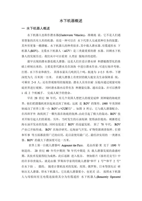
最早出现的潜水器是载人潜器,这是人们在设计潜水球和潜艇微型化的基础上研制出来的,主要是替代潜水员在深海中进行潜水作业,可进行海洋考察、打捞、水下作业和救生。
其排水量从几吨到几十吨,航速为1~2.5 米/秒,下潜深度为几百米到一万米。
在载人潜器上有密封的载人舱室及生命保障系统,可乘坐2~3 人,还有供观察用的窥视窗,潜水人员坐在耐压舱内通过视窗对海底世界进行观察,同时潜水器内还带有各种测量仪器、通讯设备,并可以携带1 或2 个机械手。
完成人赋予的使命。
早在20 世纪50 年代,有几个美国人想把人的视觉延伸到神秘的海底世界,他们把摄像机密封起来送到了海底,这就是ROV 的雏形。
1960 年美国研制成功了世界上第一台ROV ─“CURV1” ,如图 3 所示,它与载人潜器配合,在西班牙外海找到了一颗失落在海底的氢弹,由此引起了极大的轰动,ROV 技术开始引起人们的重视。
另外,当时发生的石油短缺使得油价提高,刺激着近海石油开发业的发展,同时也促进了ROV 的迅猛发展。
到了70 年代,ROV 产业已开始形成,ROV 在海洋研究、近海油气开发、矿物资源调查取样、打捞和军事等方面都获得广泛的应用,是目前使用最广泛、最经济实用的一类潜水器。
ROV 的最大下潜深度可达一万米。
世界上第一台载人潜器叫Argonaut the First,是由西蒙·莱克于1890 年制造的。
20 世纪60 年代中期到70 年代中期是从载人潜器发展的鼎盛时期,其技术发展得较为成熟,此后逐渐进入低谷。
水下机器人设计及其应用一、引言近年来,随着科技的迅猛发展及人们对海洋资源的需求不断增加,水下机器人在勘探、采集、探测等领域得到了广泛应用。
本文将深入介绍水下机器人的设计原理及其在海洋勘探、深海研究等领域的应用。
二、水下机器人的设计原理1.水下机器人的结构水下机器人一般由浮力模块、动力系统、控制模块、传感器等部分组成。
其中,浮力模块主要用于维持水下机器人的浮力,在深海探测中,浮力模块通常由球型蓝色玻璃、聚氨酯泡沫、太阳能电池板等材料制成,并安装在其外壳的上部,以在海面上获得充分的日照能量。
动力系统主要提供机器人的前进动力,包括推进器、电动机、节流阀等。
控制模块则用于控制机器人的运行方向和速度,主要由计算机、控制器、信号处理器等组成。
传感器则主要用于检测水下机器人周围的环境信息,例如水温、水深、水压、溶解氧、光照等。
2.水下机器人的动力系统水下机器人的动力系统通常由立式或水平安装的一组推进器、舵机、电机、电源等组成。
推进器通常有螺旋桨、水流喷射装置、振荡器等,而电机则用于驱动各种设备。
电源则可以是电池、太阳能电池板、燃油电池等。
3.水下机器人的控制系统控制系统是水下机器人非常重要的一部分,其作用是控制机器人的运行,使其能够在水下完成需要的任务。
控制系统可以由一台单独的计算机控制,也可以由多个传感器和控制器组成。
控制器通常由多种传感器组成,例如水温传感器、水压传感器、声纳传感器等。
三、水下机器人的应用1.海洋探测水下机器人在海洋探测中有着广泛的应用,可以用于寻找石油、天然气、瑞氏波、气体水合物等,在深海地壳构造、地震构造、海底资源分布等方面起着重要的作用。
水下机器人还可以搭载各种海洋仪器,例如深海测量仪、海洋生物学仪器、物理化学分析仪等,以获得更为丰富的数据。
2.深海研究水下机器人因其能够潜入几千米深的水下,使其成为深海研究的有力工具。
水下机器人不仅可以搭载各种观测仪器,还可以进行深海岩芯采集、岩石取样等任务,从而为深入了解深海地貌、海底热液、深海生物等提供了重要的数据。
引言:智能水下机器人是近年来快速发展的一项技术,具有广泛的应用前景。
本文旨在深入探讨智能水下机器人的技术原理、应用领域、发展趋势以及存在的挑战与解决方案。
概述:智能水下机器人是一种能够在水下环境中执行各种任务的机器人系统。
它具有自主感知、决策和执行能力,能够完成水下勘探、海洋科学研究、水下作业等任务。
本文将从技术原理、应用领域、发展趋势和挑战解决方案等方面进行详细阐述。
正文:1. 技术原理1.1 感知技术:智能水下机器人使用多种传感器,如声纳、摄像头、激光雷达等,实现对水下环境的感知,包括水下地形、水质、目标检测等。
1.2 定位与导航技术:采用GPS、声纳、惯性导航系统等技术,实现智能水下机器人的定位与导航,确保其能够准确执行任务。
1.3 通信与控制技术:智能水下机器人通过无线通信与地面基站进行数据传输与控制,能够实时获取指令和发送数据,保持与操作员的交互。
2. 应用领域2.1 水下勘探:智能水下机器人可以应用于海底资源勘探,如油气田勘探、矿产资源勘探等,具有高效、安全、环保的特点。
2.2 海洋科学研究:智能水下机器人可以用于海洋生物学、海洋地质学等科学研究,对于深海生物、海底地形等的研究具有重要意义。
2.3 水下作业:智能水下机器人在水下维修、检测、清洁等方面能够发挥作用,代替传统的人工作业,提高效率和安全性。
3. 发展趋势3.1 多功能化:未来智能水下机器人将更加注重多功能化,能够同时执行多种任务,提高工作效率。
3.2 自主化:智能水下机器人将具备更强的自主感知、决策和执行能力,独立完成复杂任务,减少人为干预。
3.3 大数据应用:通过对海底数据的收集和分析,智能水下机器人将为海洋科学研究提供更多有价值的数据支持。
4. 挑战与解决方案4.1 水下环境恶劣:智能水下机器人在水下环境中面临压力、温度、腐蚀等恶劣条件,如何保障其正常运行成为挑战之一。
解决方案包括材料选择、密封设计等。
4.2 远程通信与控制:智能水下机器人需要通过无线通信与地面基站进行远程控制,但水下通信存在信号衰减、传输延迟等问题,解决方案可以采用多通道通信、信号处理技术等手段。
水下机器人的设计及其相关技术研究第一章:水下机器人的定义和概述水下机器人,指的是能够在水下执行各种任务的机器人。
与地面或空中机器人相比,水下机器人通常需要耐受更高压力,更复杂的任务和良好的机动性能。
它们广泛应用于海洋勘探、海洋工程、水下科学探索、军事作战和水下维修等领域。
目前,水下机器人的设计与技术研究成为多学科交叉研究的热点之一。
第二章:水下机器人的分类和应用水下机器人根据其结构、用途和任务可以分为:1.遥控型水下机器人:具有高机动性和稳定性,广泛应用于海洋科学探索、潜水作业、海洋环境监测等领域。
2.自主型水下机器人:具有自主导航、感知和控制能力,适用于海底地质勘探、污染监测、水下探测等。
3.混合型水下机器人:结合了遥控和自主两种机制,可实现更加复杂的任务,如水下救援、海底安装和维护等。
水下机器人的应用场景包括:1.海洋科学探索:可用于海底地质勘探、生态环境调查、水下考古和生物学研究等。
2.水下工程:可用于海洋油气勘探和开发、海上风电场建设和维护、海底通信线路敷设和维修等。
3.海上保障:可用于水下侦察和打击、海上救援和调度、海上监测和情报收集等。
第三章:水下机器人的关键技术1.水下传感技术:水下机器人需要能够感知周围环境和水下场景,实现对目标物体的定位、跟踪和测距等功能。
水下传感技术包括声学、电磁、光学等多种技术手段。
2.水下通信技术:水下机器人的控制和数据传输需要通过水下通信系统完成。
水下通信技术瓶颈主要在于信号传输距离较短、传输速率低、干扰较大等问题。
3.水下机器人运动控制技术:水下机器人需要具备良好的机动性能和稳定性,在水下复杂环境中能够实现高精度运动状态控制。
这需要基于水下传感技术和控制理论实现。
4.水下能源和动力技术:水下机器人一般采用电池供电,电池续航能力和可靠性是水下机器人关注的热点问题。
此外,为了实现较高的工作效率和机动性能,水下机器人动力体系也需要不断改进和创新。
第四章:水下机器人的设计与制造水下机器人的设计与制造需要多学科专业共同协作和研究,从机械结构、传感器、控制算法到电机和电力系统等多个方面进行设计优化。
水下机器人技术的研究与应用第一章:介绍近年来,随着科技的不断发展,水下机器人技术也在逐步成熟。
水下机器人指的是能在水下运行的机器人,用于执行水下勘测、海底矿产开发等任务。
水下机器人技术具有诸多优势,如不受污染、能够深入水下、适用于各种复杂环境等。
本文将重点介绍水下机器人技术的研究与应用。
第二章:水下机器人技术的研究2.1 构成水下机器人技术主要由机械、电子、计算机三个方面构成。
机械包括系统的结构、附加的传动装置、动力装置,以及附加的传感器和执行器等。
电子方面则主要涉及到机器人的信号处理、通信、定位与导航、图像处理和控制系统等。
计算机则是机械和电子结合的核心部分,主要负责控制机器人的各个功能。
2.2 技术水下机器人技术包括多种技术,如传感技术、通信技术、定位与导航技术、控制技术、图像处理技术等。
其中,图像处理技术是目前发展最为迅速的技术之一。
由于水下环境的复杂性,传感和控制系统也非常重要。
特别是对于海洋工程的施工和维护来说,定位与导航技术的发展至关重要。
此外,水下机器人的能源系统、材料技术等也是水下机器人研究的重点。
第三章:水下机器人技术的应用3.1 海洋科学水下机器人能够进行深海勘测,提供大量的海洋数据,为海洋科学研究提供了重要的支持。
此外,还能够收集海底样品、观测天然气水合物等,对于海洋资源的开发有很大的帮助。
3.2 海洋工程水下机器人在海洋勘探、生态环境保护、海洋能源开发等方面具备很大的应用价值。
在海底油气勘探、海底管线建设、水下建筑施工等方面也具有广泛的应用。
3.3 海洋保护水下机器人的高精度测量功能特别适合用于环境监测,可支持对污染水域的监测、调查和预测。
同时,水下机器人也可用于海洋物种保护,如海龟、鲸鱼等的生存状况的监测。
第四章:水下机器人技术的前景水下机器人技术是未来的发展方向之一。
将来的水下机器人将更加智能化,自主性和敏捷性更强,例如深海挖掘机器人、水下自主潜航器等。
此外,水下机器人技术的应用领域也将会更加广泛,例如水下爆炸物探测、深海生态研究等。


水下机器人在海洋安全中的技术研究海洋,占据了地球表面的约71%,蕴含着丰富的资源和无尽的奥秘。
然而,海洋环境复杂多变,给人类的探索和利用带来了巨大的挑战。
在这样的背景下,水下机器人应运而生,成为保障海洋安全的重要技术手段。
水下机器人,也被称为无人水下航行器(Unmanned Underwater Vehicle,简称 UUV),是一种能够在水下自主航行、执行任务的智能化设备。
它们可以携带各种传感器和工具,深入海洋深处,进行探测、监测、侦察、救援等工作,为海洋安全提供了有力的支持。
一、水下机器人的分类与特点水下机器人根据其控制方式和功能的不同,可以分为遥控式水下机器人(Remotely Operated Vehicle,简称 ROV)和自主式水下机器人(Autonomous Underwater Vehicle,简称 AUV)两大类。
ROV 通常通过电缆与母船相连,由操作人员在船上进行远程控制。
它们具有强大的动力和操控性能,可以携带大型的设备和工具,适用于复杂的作业任务,如深海油气开采中的设备维护、海底管道的检测等。
但由于受到电缆长度的限制,ROV 的活动范围相对较小。
AUV 则不需要与母船相连,能够自主规划航线和执行任务。
它们依靠内置的电池和计算机系统进行工作,具有较高的自主性和灵活性,可以在较大的范围内进行探测和监测。
然而,AUV 的负载能力和作业时间相对有限,通常用于一些对续航要求不高的任务,如海洋环境监测、科学考察等。
除了 ROV 和 AUV 之外,还有一些混合式水下机器人,结合了两者的优点,能够在不同的任务场景中发挥更好的性能。
水下机器人具有以下几个显著特点:1、适应恶劣环境海洋中的水压、温度、盐度等条件极其恶劣,水下机器人采用了特殊的材料和结构设计,能够承受高压、低温和腐蚀等考验,确保在深海环境中正常工作。
2、高精度探测配备了先进的传感器,如声纳、光学相机、磁力计等,能够对海洋中的地形、地貌、生物、化学物质等进行高精度的探测和测量。
![水下机器人[1]](https://uimg.taocdn.com/99d6203a5901020207409c28.webp)
水下机器人技术研究及应用第一章:引言随着科技的不断发展,水下机器人技术在工业、科研、海洋资源开发与利用等领域中受到越来越多的关注。
水下机器人是一种能够在水下自主工作的机器人,具有高效、安全的优势,对推动我国海洋经济建设以及科学研究具有重要意义。
本文将从水下机器人技术的基础概念、类型以及功能与应用等方面进行详细介绍。
第二章:水下机器人的基础概念水下机器人(Underwater Robot,UUV)是指一种能够在水下自主进行任务的机器人,它是一种富有智能化的机电一体化系统。
按照设计原理和特点,水下机器人可分为两类:遥控水下机器人和自主水下机器人。
遥控机器人一般通过遥控端或者有线通信进行操控,能够执行一定的动作或者完成一定的任务。
自主水下机器人则具备一定的自主判断、调节和控制功能,能够在无人参与控制情况下完成复杂的任务。
第三章:水下机器人的类型根据结构和用途的不同,水下机器人目前主要有以下几种类型:1. 呆滞浮力水下机器人呆滞浮力水下机器人主要采用重力锚索定位模式进行控制,下挂浮球控制浮力平衡。
它一般用于海底勘探、水文研究、水下采油等方面。
2. 遥控水下机器人遥控水下机器人通常由罗盘、深度计、输入输出单元、控制系统、图像装置、操作机构、驱动机构等组成。
它具有良好的操控能力和导航性能,广泛应用于水下观测、考古、资源调查、海洋环境监测与剖面研究等多个领域。
3. 潜水液压机械臂潜水液压机械臂是一种流体动力机械臂,它通常由水源系统、动力系统、执行机构和测量控制系统等构成。
它常被用于海底管线的连接、检查与维修等领域。
第四章:水下机器人的功能与应用水下机器人在海洋调查、资源开发、环境监测、水下作业、水下检查与维护等领域中有广泛的应用,其中一些应用实例如下:1. 海洋资源开发水下机器人可以在海底执行勘探、采样、分析与监测任务,进一步推动我国海底资源的开发利用以及海洋产业发展。
2. 海底遗址考古水下机器人通常配备探照灯、摄像机等设备,能够深入海底进行遗址拍摄、场地勘探和历史调研,有助于保护文化遗产。
水下机器人的基本特征1.引言1.1 概述水下机器人是指能够在水下环境中执行各种任务和操作的机器人。
随着科技的不断进步和水下领域的不断拓展,水下机器人在海洋工程、海洋科学研究、水下探测和救援等领域起到了至关重要的作用。
水下机器人具有许多独特的特征,使其成为水下探索和开发的重要工具。
首先,水下机器人具有良好的适应性和耐受性。
水下机器人经过优化和设计,能够在极端的水下条件下正常运行,包括深海、高压、低温等极端环境。
这使得水下机器人能够进行深海探测、海洋底部资源勘探等任务,为人类探索未知领域提供了重要支持。
其次,水下机器人具备高度灵活性和可操控性。
水下机器人通过使用先进的控制系统和传感器技术,能够准确地执行各种任务,如搜寻和回收海底文物、修复海底通信线缆等。
其灵活的结构和可调节的操作模式,使得水下机器人能够适应不同任务的需求,并且能够在复杂的水下环境中进行准确的操作。
此外,水下机器人还具备较高的自主性和智能化。
随着人工智能和机器学习技术的不断发展,水下机器人能够通过自主控制和学习,逐渐提高其自主决策和问题解决的能力。
水下机器人能够根据环境变化和任务需求,做出智能化的决策,提高任务的执行效率和准确性。
综上所述,水下机器人具有适应性强、灵活性高、自主性和智能化等基本特征。
它们在水下领域的应用前景广阔,并且随着技术的不断创新和完善,水下机器人势必会在各个领域发挥更加重要的作用,并推动水下科学研究和探索的进一步发展。
1.2 文章结构本文将按照以下结构进行叙述水下机器人的基本特征:首先,在引言部分,我们将概述水下机器人的基本概念和重要性。
通过引出本文的目的,我们会提醒读者为什么需要深入了解水下机器人的基本特征。
接下来,在正文部分,我们将首先给出水下机器人的定义,详细解释它是一种可以在水下环境中执行任务的自主机器。
我们将介绍水下机器人的工作原理,包括其结构、动力系统和控制方式等方面的内容。
通过了解水下机器人的工作原理,读者将能够更好地理解它的基本特征和功能。
- 1 -本科生课程大纲课程属性:公共基础/通识教育/学科基础/专业知识/工作技能,课程性质:必修、选修一、课程介绍 1.课程描述:水下机器人技术是海洋特色显著的专业性选修课程之一,对培养具有机械专业知识的海洋装备研发人才有积极的作用。
课程包括水下机器人结构、能源及动力系统、推进与舵、导航与定位等部分。
通过课程的学时和实践,培养学生参数计算、设备选型、结构设计和控制系统编程的能力,并能够利用这些理论和方法,对水下机器人设备进行控制、升级和改造等。
2.设计思路:开设依据:通过课程基础知识的学习,掌握水下机器人结构和控制系统的参数计算、选型和设计的方法,并将以上方法应用到水下机器人设计过程的计算、分析和研究中(支撑毕业要求的能力1.4和1.6),可针对水下机器人机的特殊需求进行功能分析、解决方案制定及科学问题研究(支撑毕业要求的能力2)。
在课程的实验环节中,学生将以小组为单位开展机器人结构设计、优化、控制软件实现等任务,将课程的理论知识用于实践中,同时锻炼学生的独立担当与团队协作能力(支撑毕业要求的能力3)。
课程内容:(一)第一章绪论:简要介绍水下机器的产生于发展历程、分类与用途及特点,并用几个案例进行分析,使得学生对水下机器人有初步认识。
(二)第二章水下机器人的结构:主要讲解水下机器人的重量特征、耐压结构的设计、舱口盖和观察窗的种类及设计、压力平衡结构、安全性和可靠性等,为后续机器人的设计打下基础。
此部分采用理论讲授和实践相结合的方式进行,将让学生动手操作典型的水下机器人,加深学生对水下机器人结构和控制的认识。
(三)第三章能源及动力装置:学生将掌握水下机器人常用的电池能源、内外燃机、电力装置和液压装置的种类和功能等,培养学生选择和设计合理的能源装置的能力。
(四)第四章推进器与舵:学生将从水下机器人的各种推进器开始认识水下机器。
通过各种推进器的对比,加深对推进器的认识。
根据水下机器人自由度的需求介绍航向控制及推进器的配置。
水下机器人在海洋生物研究中的应用研究海洋,占据着地球表面约 71%的面积,是一个神秘而又充满未知的世界。
在探索海洋生物的奥秘过程中,水下机器人正发挥着越来越重要的作用。
水下机器人,顾名思义,是能够在水下环境中执行任务的机器人。
它们的出现,为海洋生物研究带来了前所未有的机遇和便利。
首先,水下机器人能够深入到人类难以到达的深海区域。
海洋的深度使得许多地方对于人类直接观测和研究来说充满了挑战。
巨大的水压、寒冷的水温以及复杂的水流环境,都限制了人类在深海中的活动。
而水下机器人则可以克服这些困难,它们能够携带各种科学仪器和传感器,深入到数千米甚至上万米的深海,获取有关海洋生物的珍贵数据和信息。
例如,通过搭载高清摄像机,水下机器人可以拍摄到深海生物的独特形态和行为;利用声学设备,能够监测海洋生物发出的声音,从而了解它们的交流方式和生存状态。
其次,水下机器人可以进行长时间、持续性的观测。
海洋生物的活动往往具有周期性和不确定性,要全面了解它们的生活习性和生态特征,需要进行长时间的连续观察。
传统的研究方法往往受到时间、人力和物力的限制,难以实现这一目标。
水下机器人则不同,它们可以在水下长时间工作,按照预设的程序和路线进行观测,并将数据实时传输回地面控制中心。
这使得研究人员能够积累大量的连续数据,从而更准确地分析海洋生物的行为模式和生态变化。
再者,水下机器人在不干扰海洋生物的情况下进行研究。
海洋生物对环境的变化非常敏感,人类的直接介入可能会对它们的行为和生存造成影响。
水下机器人可以在一定距离外进行观测和数据采集,最大限度地减少对海洋生物的干扰。
这有助于获取更加真实和自然的生物数据,为研究提供更可靠的依据。
此外,水下机器人还能够在危险的海洋环境中工作。
比如,在一些存在有毒物质、强水流或者复杂地形的区域,水下机器人可以代替人类进行探索和研究,降低了研究人员面临的风险。
在实际应用中,水下机器人的类型和功能也多种多样。
有小型的、灵活的机器人,适合在狭窄的海底洞穴和珊瑚礁区域进行观测;也有大型的、具备强大动力和负载能力的机器人,可以在深海进行大规模的采样和调查。
Oceanographic science is frequently hindered by a lack of spatial and temporal resolution for most parameters oceanographic science desires to measure.This paper discusses our effort to advance the current state of bathymetric mapping as part of the Monterey Bay Aquarium Research Institute ͑MBARI ͒charter.MBARI scientists and engineers,in con-sultation with the external community,have produced a new multibeam mapping au-tonomous underwater vehicle ͑AUV ͒system.The system is intended to reduce some of the impediments encountered by science trying to resolve specific portions of the oceans bottom.Starting with the established and in-house developed Dorado AUV technology,MBARI engineering refined the AUV into a full ocean depth capable and now operational multibeam mapping system ͑MBAUV ͒.The MBAUV system conducts regular multibeam bathymetry,subbottom,and sidescan surveys for oceanographic science.MBAUV is a torpedo-shaped,6000m rated vehicle operating the aforementioned sonars simulta-neously.The endurance of the MBAUV is approximately 8h at 3kn and is designed to support 16h operations at 3kn by adding an additional battery section.This paper de-scribes the basics of the MBAUV and our design trades and modifications to the Dorado AUV in support of multibeam mapping missions.The paper also reviews a sampling of the results from a series of missions that demonstrate the performance of various sub-systems and the science quality data available from the MBAUV .©2007Wiley Periodicals,Inc.1.INTRODUCTIONMonterey Bay Aquarium Research Institute ͑MBARI ͒engineering and science began developing autono-mous underwater vehicles in the late 1990s.TheMBAUV project was conceived in 2003primarily to provide MBARI science with topographic mapping capabilities to address a series of eastern Pacific ge-ology questions.Since the MBAUV became opera-tional,the applicability of the system has broadened the missions to geochemistry,in situ observatory in-frastructure,environmental impact report data,and search and recovery.The subbottom profiler imagingContract grant sponsor:National Ocean Partnership Program and National Science Foundation.Contract grant numbers:N00013-98-1-0814and OPP-9910290.•••Journal of Field Robotics 24(6),487–495(2007)©2007Wiley Periodicals,Inc.Published online in Wiley InterScience ().•DOI:10.1002/rob.20191subsurface phenomenon is in demand from scienceas much as the multibeam capability.The advantageof MBAUV is you get both as well as dual frequencysidescan simultaneously.Working in conjunction with MBARI scientists,our team focused on advancements in multibeammapping from an AUV to obtain the highest resolu-tion possible in subsea canyon terrain at1.5m/s ͑3kn͒,the optimum speed of Dorado.Our belief is this compromise is superior to towfish system reso-lution while covering more territory than hoveringAUVs.Feedback from the general oceanographiccommunity as well as MBARI science indicated thiswould be a useful operational scenario and perfor-mance band.AUV development at MBARI is a relatively re-cent activity based on numerous vehicles that had al-ready proven the applicability of AUVs for science invarious configurations.Scientific multibeam map-ping from AUVs is a much more recent applicationbut also did not originate at MBARI.The early AUVdevelopments occurred years and even decades pre-vious to MBARI.Thefield of AUV development hasprogressed slowly since the SPURV system was intro-duced in the1960s͑Nodland,1968&Nodland,1976͒.There have been other more radical concepts devel-oped such as Woods Hole’s ABE͑Yoerger,Bradley,&Walden,1994͒.The majority of AUVs have not devi-ated dramatically from the early pioneering systems.Ultimately the trade we faced for our mapping sys-tem was operational speed against precision controlin difficult terrain.Ourfinal decision was to continuedevelopment of our MBARI Dorado vehicle͑McE-wen&Streitlien,2001͒as a base vehicle platform andtake advantage of the designs modularity.To reachour goals,we needed a custom mapping payloadmounted in the AUV and configured for missions lessaggressive than a hovering system but more aggres-sive than towfish.By sacrificing the most difficult ter-rain the advantage gained is the ability to cover largeareas of highly variable topography other systemswould not be able to attempt.In the mid-1990s,MBARI had participated inmapping multiple areas within the Monterey BayCanyon as well as other Pacific Ocean sites͑Greene,Maher,&Paull,2002͒.That multibeam data were col-lected using a hull mounted Simrad©EM300™multibeam sonar.The critical specification of thatmultibeam system was the2°ϫ2°beams operatingat30kHz.The approximate resolution obtained was1.7m at nadir for the upper canyon depths of ap-proximately100m depth and at the4000m deepercanyon depths that resolution was functionally68mbased as defined by a direct sine function of an in-dividual beam͑Clarke,Gardner,Torresan,&Mayer,1998͒.It is easily discerned from the previous state-ment that generally placing the sonar closer to the tar-get will improve data resolution.The advent of towfish for sonar mapping did im-prove the data resolution by placing the sonar trans-mitter and receiver closer to the bathymetry.Al-though towfish were an improvement,theinstabilities due to being towed are still a factor anda significant contributor to sonar data degradation.Ship heave inputs through the tow cable causing tow-body velocities to vary coupled with cross currents atdepth all contribute to erratic motions that induce er-rors.The combined motions of heave,pitch,roll,andyaw also significantly complicate data interpretationduring postprocessing.AUV technology addressessome of the towfish issues while keeping the desiredproximity to the bottom.We were able to incorporatethe latest navigation and sonar sensor technology,re-move the tow cable input errors,and offer tightlycontrolled terrain following capability by using ourAUV.Others have demonstrated that AUV technology,when properly implemented,gives superior perfor-mance for mapping͑Yoerger,Bradley,Walden,Singh,&Bachmayer,1998͒.We believe we have successfullyestablished bathymetric mapping for MBARI scienceusing our Dorado AUV platform as conceptualized ͑Kirkwood,Bellingham,Stannard,Stein,&Overland, 2001͒.Building on our AUV system and integratingour custom multibeam sonar we have achieved ourgoals.This paper outlines the specific technical de-tails andfield program results that distinguishMBARI’s multibeam AUV͑MBAUV͒from other plat-forms available today.2.SONAR SUBSYSTEMSTo achieve multibeam mapping of large120°swathwidths with vertical accuracies of less than0.2%ofaltitude and configured tofit within,the Dorado hullrequired a custom sonar be designed.The MBAUVdocumentation specifics summarized in Table I des-ignates the primary sonar sensor as a200kHz multi-beam.The specification also includes dual frequencychirp sidescan sonar with100and410kHz capabilityand a2–16kHz sweep chirp subbottom profiler.Fur-488•Journal of Field Robotics—2007Journal of Field Robotics DOI10.1002/robthermore,all three sonars are required to operate si-multaneously.The operational scenarios and need for attitude data to correct sonar data forced the decision for very high precision attitude,heading,and refer-ence sensors.The major driver to support the reso-lution of the multibeam sonar was a requirement for the attitude sensor to provide0.01°absolute roll in-formation at a minimum frequency offive times the multibeam ping rate.The oversampling is needed to reduce roll bias from thefiltered navigation system data.The multibeam also required precise synchro-nization timing to assemble maps at the optimum resolution.These science requirements and scenarios are the input to core capabilities that outline what we believe is a versatile and robust AUV system for MBARI science͑Caress,&Kirkwood,2001͒.The mapping sonar payload is mounted in a purpose built independent midsection.A chirp subbottom profiling sonar͑2–16kHz͒and port and starboard sidescan sonar staves͑120and410kHz each͒are electrically connected and mounted alongside a tita-nium pressure vessel,which houses power supplies, a Windows2000computer,and the sonar electronics. The pressure vessel also houses a Windows XP com-puter that is responsible for running the multibeam sonar and storing all of the payload data.A200kHz projector is used for the multibeam system mounted in a“T”configuration at the bottom center forward of the receive ring for the multibeam͑Blondel&Mur-ton,1997͒.Figure1shows the selected design approach for the sonar payload section.The need to operate sonars simultaneously raised concerns that acoustic har-monics potentially could impede or saturate adjacent sonar receivers.Extending the vehicles length gave each sonar subsystem an isolated volume allowing for barrier walls and syntactic foamfloatation to be placed as enhanced dampening of internally trans-mitted noise.This design,combined with careful tim-ing and operational limits on the acoustic devices,has led to exceptional performance.Simultaneous opera-tions are managed by the Reson©proprietary timing algorithm implemented in the main sonar computer software.The system is synchronized by a1pulse per second͑1pps͒clock.The1pps is made available by the navigation system GPS and used to synchronize a stable internal clock source.Testing has proven our approach meets all sci-ence requirements over a wide range of operational missions.The predominant source of sonar interfer-ence experienced infield expeditions stems from an occasional variation in return settings of the300kHz Doppler velocimeter logging͑DVL͒.The DVL sonar performs an autoadjust when the bottom lock is lost. This operational mode of the DVL is necessary to maintain the best possible navigation by switching to water tracking versus allowing free inertial drift.The occurrence of the interference is now relatively rare but if interference does occur the DVL creates a post-processing anomaly easily identified as an incongru-ent bottom.The interference when seen in the raw multibeam data shows a semicircular pattern of beams.The data are easily corrected in preprocessing by removing the anomalous data points from the raw multibeam bottom pick data.A sample of the inter-ference is shown in Figure2where the bottom is dis-tinct from the DVL-introduced ing freely available software tools for editing multibeam data, such as MB-System͑Caress&Chayes,1996;Caress, Spitzak,&Chayes,1996͒,science users can remove the errant pings while keeping the useful bottom data.Running at a constant altitude and having some knowledge of the likely bottom makeup we haveTable I.Summary specifications for the sonarpayloads.Mapping Sonar Specifications•Reson7100Multibeam Sonar•200kHz•Circular receive array—Currently using7125modelwithflat receive array•0.94°ϫ0.94°beams•Nadir footprint by altitude:•30cm at20m•1.5m at100m•213beams reported across a maximum150°swath•Paroscientific UCB7000-I-005pressure sensor0.005%precision for vehicle depth•Speed of sound calculated using Sea-Bird SBE-49FastCat CTD•Edgetech110/410kHz chirp sidescan sonars•Images seafloor character andfine-scale features͑ϳ10cm resolution͒•Edgetech2–16kHz chirp subbottom profiler•Images subsurface sediment structureWilliam Kirkwood:Autonomous Underwater Vehicle Mapping at MBARI•489 Journal of Field Robotics DOI10.1002/robFigure 2.A typical semicircular interference pattern in the multibeam raw data looking alongtrack.Figure 1.Illustration of the sonar payload section and mounting in the center of a Dorado vehicle base.Note the purposeful separation and use of syntactic foam ͑light blue ͒as baf fling to enable simultaneous operations.490•Journal of Field Robotics —2007Journal of Field Robotics DOI 10.1002/roblearned to tune the system such that the DVL loss of bottom lock is infrequent,which removes most inter-ference with the multibeam.3.DORADO MAPPING VEHICLE PLATFORM Dorado originated from the Odyssey IIb vehicle de-veloped at the Sea Grant Office on the Massachusetts Institute of Technology campus by Bellingham͑Bell-ingham&Leonard,1994͒.The obvious difference be-tween the two vehicles is the ducted ring tail control surface.The aft end of the Dorado MBAUV uses the MBARI patented propulsion system.Decisions to fur-ther refine the AUV mapping system included modi-fying the tail section to accommodate the advanced navigation system so that it is available for other AUV applications.Propulsion is provided by a brushless dc motor coupled through a reduction gearbox to the ducted propeller and although noisy we did not modify this portion.The pulse width modulation drive electron-ics were altered from the“off-the-shelf”configura-tion of approximately25kHz to operate in the mid-30kHz frequency range to move to a unique opera-tional frequency͑Kirkwood,Griese,Shane,Au,Mel-linger,O’Reilly,et al.,2001͒.Changing the motor pulse width modulation moved the noise away from the Sonardyne©ultrashort baseline͑USBL͒system tracking to4000m so that all systems operate at unique primary frequencies.The USBL allows the surface ship to easily aid navigation by sending up-dates through the acoustic modem.The engineering goal of this effort was in anticipation of potential later problems and ease of solving them.Should we en-counter noise on the data,it is easier to trace the pri-mary frequency and harmonics by keeping all sys-tems in a unique frequency band when possible.The other goal for using this approach was to prevent the required permits needed for long baseline beacon de-ployments otherwise needed for pending operations in the Monterey Bay Sanctuary.Other modifications include the addition of an Iridium satellite modem,an ARGOS satellite tracking unit,power converters,and various other electronics to run the strobe light and10kg drop weight.The system length was increased from the minimum of 223.5cm͑88in.͒to the current MBAUV length of 609.6cm͑240in.͒to accommodate the different pay-load and power configurations͑Johnson,Paull,Barry, &Chavez,2001͒.Dorado is a freeflooding vehicle,meaning the internal structures are not maintained at one atmosphere.The main vehicle computer is housed in a glass sphere rated to6000m͑approxi-mately20,000feet͒.The vehicle exterior hull provides the majority of the strength and integrity for the ve-hicle.The hull sections are vacuum formed acetyl-butyl-styrene͑ABS͒and provide a lightweight corrosion-free base that performs as an acoustic win-dow for all of the sonars.The MBAUV design also supports the AUV being quickly reconfigured into a remotely operated vehicle ͑ROV͒payload.This modular approach allows cus-tom payloads to be inserted easily and deployed in an AUV operational mode.Figure3shows themapping Figure3.The MBARI mapping system has two opera-tional modes.For early testing the core AUV was mounted on ROV Ventana.The success of this configuration in rela-tively tight sections of the Monterey Canyon has made this a standard available operational mode.The predominant mode is to operate as an autonomous vehicle.William Kirkwood:Autonomous Underwater Vehicle Mapping at MBARI•491 Journal of Field Robotics DOI10.1002/robAUV vehicle mounted to the ROV Ventana and in the standard mode for autonomous operations.The ROV operational mode also allows the system to operate in dangerous terrain such as places where the speed and flight characteristics of the AUV have a high likeli-hood of hitting bottom.MBAUV/ROV mapping of the Monterey Bay Canyon and the challenging terrain presented has demonstrated this configuration is beneficial,having the ability to maneuver around or under narrow outcrops and other hazards.4.NAVIGATION SUBSYSTEMSThe MBAUV modified tail section carries the inte-grated package of a Kearfott©ring laser gyro com-bined with a RD Instrument©͑now Teledyne RDI©͒Workhorse™and sold as a SeaDeViL™.The instru-ment provides0.05%of distance traveled error when the DVL has a bottom lock.The multibeam receive ar-ray is mechanically coupled to the SeaDeViL™through plates that interlock providing stability be-tween the two components and eliminating any translation or rotation while operating.Acoustic com-munication,long baseline navigation,and ultrashort baseline navigation transducers are mounted further aft in an isolated section.Behind the transducers,act-ing as an additional acoustic shield from the drive motor is a17-in.-diam͑0.432m͒borosilicate glass housing.The housing holds the main vehicle com-puter as well as surface communications equipment. The acoustic modem improves navigation during deep operations by enabling surface aided navigation from the ship to the AUV.Performance of0.034%error of distance traveled has also been achieved using the SeaDeViL™.To ac-complish that level of performance requires bottom lock and GPS initialization be achieved at the same moment.Running missions from shallow bottoms to-ward deeper ones can minimize or eliminate free in-ertial drift,thereby yielding better navigational accu-racy and geolocation of thefinal data products.Figure4illustrates the mission planning use of existing EM300multibeam maps as a tool for MBAUV routes when the data are available.The mis-sion planner uses the topography as an input for the mission track lines,which the vehicle uses as a pre-dictive tool for obstacle paring alti-tude data and position within the bounds of expected error,the system anticipates vertical changes in the terrain and will pitch up or down,accordingly.We have gained experience over the last year and are now able to operate in canyons where we previously would only have taken the MBAUV/ROV configu-ration.Figure5shows how mission plans alsocon-Figure4.Typical application of the existing bathymetric data being used as part of the MBAUV vehicle mission planning.The existing topology is entered in the mission plan with minimum altitude parameters.Together these contribute to the mission plan by providing predictive in-put to the vehicle allowing the system to dive in and out of steepterrain.Figure5.Planned route using EM300data taken from Figure4overlaid on the resulting MBAUV multibeam data in a region of Barkley Canyon.Note the initial swath bathymetry errors still to be corrected where the terrain is exceptionally steep.492•Journal of Field Robotics—2007Journal of Field Robotics DOI10.1002/robsider the best route to capture details for speci fic ar-eas.The cross track lines are required to later process the data for science and create a high quality resolu-tion multibeam topographic map.The plan attempts to maximize MBAUV climbs at the steepest terrain for later postprocessing consistency.5.DATA COLLECTION AND MAPPINGMBAUV multibeam maps provide an average 30-fold increase in resolution against initial ship-based sur-veys of the Monterey Bay.The MBAUV system was intended to enhance continuing studies as shown in Figure 6but also to enable new science.To that end,the MBAUV increase in resolution and the ability to dive into the canyon has enabled mapping studies to look at canyon mass transport events down the can-yon axis.The AUV platform is also enabling obser-vatory technologies by assisting with the planning and permitting for the installation of systems like the MARS ͑Monterey Accelerated Research Site ͒facility.Since MBAUV became fully operational,we have regularly updated software and firmware to modify the initially crude beam forming and bottom detec-tion algorithms.Recent multibeam maps show a sub-stantial improvement in swath matching and resolu-tion of the processed subbottom as well as sidescan data.The MBAUV is still using a flat Reson©7125re-ceive array instead of the speci fied circular 7100re-ceive array.The circular array subcomponents are intesting at the time of this writing prior to final inte-gration.The subbottom pro filer was the first sonar in-tegrated and is performing to speci fications as illus-trated in Figure 7.When mounted on the ROV Ventana the low operational frequency of the subbot-tom leaves it susceptible to acoustic interference from hydraulic systems,which to date has precluded the collection of good subbottom data during ROV-mounted surveys.Previous sidescan data had been marred by noise and was not useful for science pur-poses.The problem was solved by revising the power system filtering and improving shielding of the acoustic modem electronics.These power modi fica-tions were implemented prior to our August 2006cruise to Barkley Canyon and Axial Seamount cruises.Figure 8shows the resulting 100kHz sides-can data from a dive on the Gorda Ridge of the Juan de Fuca plate at Axial Seamount.The image shows the sidescan data contrasted with the simultaneously collected multibeam data.The subbottom pro filer is currently investigating sedimentation in and around the Upper Monterey Canyon ͑Caress &Kirkwood,2001͒.Despite the in-complete state of the multibeam sonar,the processed bathymetry data is meeting the speci fied science re-quirements for mapping and we expect to achieve considerably improved performance when the final firmware and hardware upgrades are installed.There are four ROV-mounted near-bottom sur-veys along the Monterey Canyon axis repeated trian-nually to monitor changes in the canyon morphology.These areas are associated with the frequent sediment transport events that are known to occur in the upper canyon ͑Johnson,Paull,Barry,&Chavez,2001͒.We also conducted a detailed large-scale surveyonFigure parison of multibeam bathymetry resolu-tion achieved in water depths of 1000–1400m using ͑A ͒a hull-mounted 30kHz multibeam and ͑B ͒the MBARI Map-ping AUV operated at an altitude of ϳ60m showing the same area andscale.Figure 7.The subbottom image is typical of the MBAUV performance.The image shows the stratigraphy of the mapping line in red.The blue dashed circle illustrates the subbottom representation of a mud volcano and how gas in the sediment is revealed by deformation and lack of detailed strata.William Kirkwood:Autonomous Underwater Vehicle Mapping at MBARI •493Journal of Field Robotics DOI 10.1002/robSmooth Ridge,north of Monterey Canyon,during the latter half of 2005.This mission was in support of the Monterey Accelerated Research System ͑MARS ͒cable to con firm a safe route over rough terrain where it crosses the San Gregorio fault line.Since our first multibeam mission in 2005the MBAUV has per-formed surveys in the Santa Monica Basin ͑Figure 9͒,Barkley Canyon,Axial Seamount,Davidson Sea-mount,and the Santa Barbara Channel.6.CONCLUSIONThe MBARI sea floor mapping team began designing the MBAUV in January 2003.The Dorado-based MBAUV system has successfully met all of the origi-nal project goals with proven performance at a series of local and remote expedition sites.Every dive series of the system to date has provided high resolution science quality oceanographic data.We view MBAUV as a specialized approach to multibeam mapping in comparison to other available systems.There are few science institutions operating mapping AUVs and fewer still with matching performance and capabilities of MBAUV .We are not proposing that any single AUV provides a complete solution for oceanographic mapping.We do assert,however,that the Dorado-based MBAUV has successfully demon-strated the usefulness of both the modularity concept inherent in the Dorado platform and the ability to successfully carry intricate payload sections.Our ex-perience,we believe,also demonstrates that MBAUV can successfully operate from ships of opportunity as we have launched and recovered from 25m boats such as the R/V Zephyr and the AGOR class UNOLS vessel R/V Thomas Thompson.The MBAUV initial sea trials began in April 2004and by May 2004the MBAUV subbottom pro filer sur-veyed the upper Monterey Canyon.Those surveys provided the first mapping journal paper incorporat-ing MBAUV data ͑Paull,Mitts,Ussler,Keaten,&Greene,2005͒.Initial multibeam tests commenced in November 2004with a series of near-bottom,ROV-mounted surveys at four sites along the Monterey Canyon axis.The ROV mount concept was intended to provide immediate feedback and control during the test phase only.The processed data from the MBAUV/ROV con figuration of the system delivered 10cm vertical resolution at the narrowest points of the Monterey Canyon.That MBAUV/ROV data suc-cess created unanticipated science demand for repeat surveys of the geomorphology in the canyon axis and has made the MBAUV/ROV con figuration for opera-tions a mission mode available onrequest.Figure 8.100kHz sidescan data are shown on the left and contrasted with the corresponding multibeam on a site SE of the Axial Sea Mountcaldera.Figure 9.The Redondo Canyon off the coast of southern California showing plunge pools and the related subbot-tom strati fication with hard rock exposure and sedimentation.494•Journal of Field Robotics —2007Journal of Field Robotics DOI 10.1002/robThe MBAUV vehicle itself has proven to be ro-bust and the operational team is now adept at execut-ing missions thatfly into the extreme and challenging topography of Monterey Canyon.The system and the obtained skills have also been put to use in other can-yons such as Barkley Canyon100km west of Vancou-ver Island.Despite the current“incomplete”state of the multibeam sonar,the processed bathymetry data has met the science requirements as originally speci-fied.We expect to achieve considerably improved performance when thefinalfirmware and hardware upgrades are installed in the coming year as we pre-pare for Sea of Cortez missions in early2008. ACKNOWLEDGMENTSThis work has been supported by the David&Lu-cile Packard Foundation.REFERENCESBellingham,J.G.,&Leonard,J.͑1994May͒.Task configu-ration with layered control.Conference Proceedings, IARP Mobile Robots for Subsea Environments, Monterey,CA.Blondel,P.,&Murton,B.J.͑1997͒.Handbook of Seafloor Sonar Imagery.New York:John Wiley and Sons. Caress,D.W.,&Chayes,D.N.͑1996͒.Improved process-ing of Hydrosweep DS Multibeam Data on the R/V Maurice Ewing.Marine Geophysical Researches,18, 631–650.Caress,D.,&Kirkwood,W.͑2001͒.High resolution map-ping with AUVs;payload development issues in sup-port of oceanographic science.Oceanology International—Americas Conference.AUV Sensor Workshop Proceedings,Miami,FL.Caress,D.W.,Spitzak,S.E.,&Chayes,D.N.͑1996͒.Soft-ware for multibeam sonars.Sea Technology,37,54–57.Clark,J.E.H.,Gardner,J.V.,Torresan,M.,&Mayer,L.͑1998,September͒.The limits of spatial resolutionachievable using30kHz multibeam sonar:Model predictions andfield results.Proceedings IEEE Oceans.Nice,France,Vol.3,1823–1828.Greene,H.G.,Maher,N.M.,&Paull,C.K.͑2002͒.Physi-ography of the Monterey Bay National Marine Sanc-tuary and implications abut continental margin devel-opment.Marine Geology,181,55–82.Johnson,K.S.,Paull,C.K.,Barry,J.P.,&Chavez,F.P.͑2001͒.A decadal record of underflows from a coastal river into the deep sea.Geology,29͑11͒,1019–1022. Kirkwood,W.,Bellingham,J.,Stannard,J.,Stein,P.,& Overland,J.͑2001͒.Development of Dorado/ALTEX vehicle and subsystems.Society for Underwater Technology—AUV Masterclass Symposium Proceed-ings.Southampton Oceanographic Centre,Southamp-ton,England.Kirkwood,W.,Griese,M.,Shane,F.,Au,D.,Mellinger,E., O’Reilly,T.et al.͑2001January͒.MBARI/MIT ducted propeller control system developed for autonomous underwater vehicles.Underwater Intervention2001 Conference Proceedings,Tampa Bay,FL. McEwen,R.,&Streitlien,K.͑2001,August͒.Modeling and control of a variable length AUV.12th International Symposium on Unmanned Untethered Submersible Technology,Durham,NH.Nodland,W.E.͑1968͒.A general description of the self-propelled underwater research vehicle͑APL-UW 6814͒.Applied Physics Laboratory,University of Washington.Nodland,W.E.͑1976,September͒.Several applications of unmanned,free swimming submersibles in oceano-graphic research.4th International Ocean Develop-ment Conference,Tokyo,Japan.Paull,C.K.,Mitts,P.,Ussler,W.,III,Keaten,R.,&Greene,G.H.͑2005͒.Trail of sand in upper Monterey Canyon:Offshore California.Geological Society of America Bulletin,117,1134–1145.Yoerger,D.R.,Bradley,Albert M.,&Walden,B.͑1994, May͒.System testing of the autonomous Benthic ex-plorer.International advanced robotics programme: Workshop on mobile robots in subsea environments, Monterey,CA.Yoerger,D.,Bradley,A.,Walden,B.,Singh,H.,&Bach-mayer,R.͑1998͒.Surveying a subsea lavaflow using the autonomous benthic explorer͑ABE͒.International Journal of Systems Science,29͑10͒,1031–1044.William Kirkwood:Autonomous Underwater Vehicle Mapping at MBARI•495 Journal of Field Robotics DOI10.1002/rob。