GZL—cpld讲座1(绪论)
- 格式:ppt
- 大小:588.50 KB
- 文档页数:12


《可编程逻辑器件与应用专题》讲义附实验指导书清华大学电子工程系第一章绪论§1.1 可编程ASIC综述为特定的产品或应用而设计的芯片被称为专用集成电路ASIC(Application Specific Integrated Circuits),除了全定制的专用集成电路外,目前有五种半定制的元件,可实现ASIC的要求,它们是:*可编程逻辑器件(PLD)*复杂可编程逻辑器件(CPLD)*现场可编程门阵列(FPGA)*门阵列(Gate Array)*标准单元(Standard Cell)在这些器件中,尤其是前三种器件的出现,使得电子系统的设计工程师利用相应的EDA软件,在办公室或实验室里就可以设计自己的ASIC器件,其中近几年发展起来的CPLD和FPGA格外引人注目。
这三种器件都具有用户可编程性,能实现用户需要的各种专门用途,因此被称作可编程专用集成电路。
半导体制造厂家可按照通用器件的规格大批量生产这种集成电路,作为一种通用集成电路,用户可以从市场上选购,再通过设计软件编程实现ASIC的要求。
由于这种方式对厂家和用户都带来了好处而受到欢迎,因此发展特别迅速,已经成为实现ASIC的一种重要手段。
随着半导体技术的迅速发展,从八十年代开始,构造许多电子系统仅仅需要三种标准电路:微处理器,存储器和可编程ASIC。
电子系统设计的这场革命是从70年代开始的,当时存储器已经作为标准产品进入市场,而80年代的微处理器也成为一种标准产品。
值得注意的是,微处理器和存储器作为电子系统的两个主要模块,一直都是可编程的。
但是组成电子系统的各种控制逻辑仍然需要大量的中小规模通用器件。
直到近十年来,随着可编程逻辑器件的出现,才给电子系统的控制逻辑提供了可编程的灵活性。
而可编程门阵列作为一种高密度,通用的可编程逻辑器件与它的开发系统一起为更多的电子系统逻辑设计确定了一种新的工业标准。
越来越多的电子系统设计工程师用CPLD或FPGA作为电子系统设计的第三个模块来实现一个电子系统。
一、教学目的与要求:本课程属于应用型课程,主要学习基于可编程逻辑器件的数字系统的设计。
课程的任务是掌握硬件描述语言、可编程逻辑器件原理以及开发平台的使用,并熟练应用硬件描述语言描述数字电路,直至能用硬件描述语言设计数字系统。
要求学生在学习本课程之前,透彻理解数字电路知识,这样才能达到本课程教学目的:应用硬件描述语言描述电路,设计数字系统。
通过讲课、演示,只能传授给学生基本方法。
这门课程的学习需学生自己课后化一定的时间练习。
半定制器件设计原理课程是数字逻辑与设计电路课程的延续和补充,本课程的重点是用软件编程的方法设计数字系统。
本课程与数字逻辑与设计电路课程相比,设计电路的原理相同,实现方法不同。
在传统的数字电路中,设计电路,画出原理图后,选择器件,连线,完成设计。
这种设计方法是自底向上的设计方法。
在设计过程中,容易出错或难以修改。
利用半定制器件设计原理中的集成开发环境QuartusⅡ,如用原理图输入法,设计好原理图,在原理图编辑窗口输入原理图,下面的大部分工作由QuartusⅡ帮助你完成;如用QuartusⅡ的文本输入法,只需描述所要设计电路的功能,而不必画出原理图。
这种设计方法是自顶向下的设计方法,使得设计人员的大部分精力放在电路整体功能的实现上。
设计电路的关键是要对所设计电路的功能了解的非常透彻。
如设计一位8421BCD 码加法器,有几个输入端,有几个输出端?输出信号与输入信号有什么关系?本实验指导书和上课内容、作业密切相关。
实验指导书上的内容是必做实验内容。
实验课时为16,实验个数为8个。
教科书上的课后练习、实验以及上课时所讲例题由同学课后自行练习。
二、实验须知实验课也是正规的课。
在实验过程中,严禁使用手机,一旦发现,指导教师有权没收。
实验课与课堂教学相同,要求同学带笔,带笔记,带教科书。
同时请同学们遵守实验室的规章制度,不允许乱搬仪器。
如有需要,告知指导教师,由指导教师安排。
实验一用VHDL语言设计组合、时序电路(2学时)实验目的:掌握用VHDL语言设计组合、时序电路的方法。


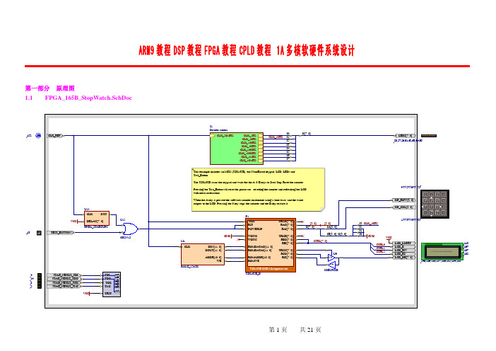
ARM9教程DSP 教程FPGA 教程CPLD 教程 1A 多核软硬件系统设计第一部分 原理图1.1 FPGA_165B_StopWatch.SchDoc1323144152240,239,238,237,236,235,234,2331.3StopWatch.ASM ;............................................................................... PortAsInput.equ 0xFFPortAsOutput.equ 0x0KeyPad.equ PORTA; Out on the TRIS Lines used as ouputsLCD_CTRL.equ PORTB; LCD control lines interfaceLCD_DATA.equ PORTC; LCD data lines interface (bidirectional); LCD_CTRL control bitsLCD_E.equ LCD_CTRL.0 ; LCD Enable control lineLCD_RW.equ LCD_CTRL.1 ; LCD Read/Write control lineLCD_RS.equ LCD_CTRL.2 ; LCD Register-Select control line;LCD_DATA feedback:LCD_BUSY.equ LCD_DATA.7 ; high if BUSY;LCD commands:LCD_ClearScreen.equ 0x01LCD_ReturnHome.equ 0x02LCD_SetEntryMode.equ 0x04LCD_SetDisplayMode.equ 0x08LCD_SetCursorMode.equ 0x10LCD_SetFunction.equ 0x20LCD_SetCharMapAddress.equ 0x40LCD_SetDisplayAddress.equ 0x80;LCD EntryMode masks:LCD_ShiftDisplay.equ 0x01LCD_ShiftIncrement.equ 0x02;LCD DisplayMode masks:LCD_BlinkingOn.equ 0x01 LCD_BlinkingOff.equ 0x00 LCD_ShowCursor.equ 0x02 LCD_HideCursor.equ 0x00 LCD_DisplayOn.equ 0x04 LCD_DisplayOff.equ 0x00; Keypad ID:Key_1.equ 0x0 Key_2.equ 0x1 Key_3.equ 0x2 Key_C.equ 0x3 Key_4.equ 0x4 Key_5.equ 0x5 Key_6.equ 0x6 Key_D.equ 0x7 Key_7.equ 0x8 Key_8.equ 0x9 Key_9.equ 0xA Key_E.equ 0xB Key_A.equ 0xC Key_0.equ 0xD Key_B.equ 0xE Key_F.equ 0xF Key_Up.equ Key_1 Key_Left.equ Key_4 Key_Right.equ Key_6 Key_Down.equ Key_9 Key_INVALID.equ 0xFF;...............................................................................Is2Pwr.MACRO value ; Check if value is a power of 2 (if it is "Z" is set) DECF value,W; if value is a power of 2, only one bit is set,ANDWF value,W; so that value and (value - 1) have no common bits .ENDM;................................................................................section data, data; Data used:StopWatch_Mode.dsb 1 ; 0=Stop 1=Count 2=resetMinutes_X1.dsb 1 ; Stopwatch, minutes/ones digitMinutes_X10.dsb 1 ; Stopwatch, minutes/tens digitSeconds_X1.dsb 1 ; Stopwatch, Seconds/ones digitSeconds_X10.dsb 1 ; Stopwatch, Seconds/tens digitTenthSeconds.dsb 1 ; Stopwatch, 1/10ths digitTemp.dsb 1 ; Tempory which may be used for *any* leaf function CountInner.dsb 1 ; Storage needed by Delay100usCountOuter.dsb 1 ; Storage needed by Delay100usCurrentKey.dsb 1 ; Latest key scanned by the KeyScan function StringOffset.dsb 1 ; String lookup table offset;................................................................................section bit, bitLastTime.dsbit 1;................................................................................section Entry, Code, at(0)__start: ; Entrypoint of hardwareGJMP Main;................................................................................section stopwatch, code, inpage ; inpage allows for interesting optimizations for; jumps and call within this section. However it is; requiered NOT to change the code-pagebits directly.; For calls and jumps out of the scope of the section,; CALL/LCALL and GOTO/LJMP must be used.; Also the section must fit in one page (512 instr.);...............................................................................;Jump table for CALLs; CALL instruction only allows 8 bit address so use a jump table; CALL the Jump table which does a GOTO the address ;...............................................................................KeyScan: GOTO Do_KeyScanDisplayStartupMessage: GOTO Do_DisplayStartupMessageLCD_Initialize: GOTO Do_LCD_Initialize;...............................................................................; Lookup tables: ;...............................................................................Lookup_StartupString1:ADDWF PCL,fRETLW'Stop Watch Demo',0Lookup_StartupString2:ADDWF PCL,fRETLW'A:Go 0:Stp B:Rst',0Do_LookupTable_Character:ADDWF PCL,f;RETLW '0123456789ABCEF'RETLW'123C456D789EA0BF';............................................................................... ; HandleKeyPress:; selects the right action when a key-press is pressed ;............................................................................... HandleKeyPress:MOVF CurrentKey,WANDLW 0xFADDWF PCL,fGOTO HandleKey_Null; 1GOTO HandleKey_Null; 2GOTO HandleKey_Null; 3GOTO HandleKey_Null; CGOTO HandleKey_Null; 4GOTO HandleKey_Null; 5GOTO HandleKey_Null; 6GOTO HandleKey_Null; DGOTO HandleKey_Null; 7GOTO HandleKey_Null; 8GOTO HandleKey_Null; 9GOTO HandleKey_Null; EGOTO Watch_Start; AGOTO Watch_Stop; case 0GOTO Watch_Reset; BGOTO HandleKey_Null; FWatch_Stop:CLRF StopWatch_Mode; Switch Stopwatch mode to "Stop" and fall through; to "RETLW" of HandleKey_NullHandleKey_Null:RETLW 0Watch_Start:MOVLW 1 ; Switch Stopwatchmode to "Start"MOVWF StopWatch_ModeGOTO Watch_Display; "Watch_Display" will return to callerWatch_Reset:MOVLW 2 ; Switch Stopwatchmode to "Reset"MOVWF StopWatch_ModeCLRF Seconds_X1CLRF Seconds_X10CLRF Minutes_X1CLRF Minutes_X10CLRF TenthSeconds; GOTO Watch_Display ; Fall through to "Watch_Display"; "Watch_Display" will return to caller;...............................................................................; Watch Display:; Updates display text according to the values in the timer-bytes ;...............................................................................Watch_Display:MOVLW LCD_SetDisplayAddress | 0x49 ; Cursor to position 8 in second rowCALL LCD_SendCommandMOVLW 10CALL Delay100usMOVLW'0'ADDWF Minutes_X10,W CALL LCD_SendCharacterMOVLW 10CALL Delay100us MOVLW'0'ADDWF Minutes_X1,W CALL LCD_SendCharacterMOVLW 10CALL Delay100us MOVLW':'CALL LCD_SendCharacterMOVLW 10CALL Delay100us MOVLW'0'ADDWF Seconds_X10,W CALL LCD_SendCharacterMOVLW 10CALL Delay100us MOVLW'0'ADDWF Seconds_X1,W CALL LCD_SendCharacterMOVLW 10CALL Delay100us MOVLW'.'CALL LCD_SendCharacterMOVLW 10CALL Delay100usMOVLW'0'ADDWF TenthSeconds,WCALL LCD_SendCharacterRETLW 0;............................................................................... ; Delay100us:; This function will consume (W * (99 * 4 + 4)) + 3 == (W * 400) + 3 cycles; At 40Mhz processor clock, this will generate a W * 100 uSecs software delay ; Note: if W is zero, the function will consume (256 * 400) + 3 cycles ;............................................................................... Delay100us:MOVWF CountOuterLoopOuter:MOVLW 99MOVWF CountInnerLoopInner:NOPNOPDECFSZ CountInner,fGOTO LoopInnerDECFSZ CountOuter,fGOTO LoopOuterRETLW 0;............................................................................... IncrementTime:INCF TenthSeconds,f; Increment the TenthSeconds countMOVLW 10 ; Do we need to roll over?SUBWF TenthSeconds,WBTFSS CRETLW 0 ; If not then display the timeCLRF TenthSecondsINCF Seconds_X1,f; Increment the sec (ones) countMOVLW 10 ; Do we need to roll over?SUBWF Seconds_X1,WBTFSS CRETLW 0 ; If not then display the timeCLRF Seconds_X1; Clear the sec (ones) countINCF Seconds_X10,f; Increment the sec (tens) countMOVLW 6 ; Do we need to roll over?SUBWF Seconds_X10,WBTFSS CRETLW 0 ; If not then display the timeCLRF Seconds_X10; Clear the sec (tens) countINCF Minutes_X1,f; Increment the min (ones) countMOVLW 10 ; Do we need to roll over?SUBWF Minutes_X1,WBTFSS CRETLW 0 ; If not then display the timeCLRF Minutes_X1; Clear the min (ones) countINCF Minutes_X10,f; Increment the sec (tens) countMOVLW 6 ; Do we need to roll over?SUBWF Minutes_X10,WBTFSC CCLRF Minutes_X10; Clear the min (tens) countRETLW 0;...............................................................................;Sends command to LCD;Required command must be in W ;...............................................................................LCD_SendCommand:MOVWF Temp; Store command in tempMOVLW PortAsInputTRIS LCD_DATA; Set Port To Inputs.gen REPEATBCF LCD_E; Disable LCD - Set Enable LowBSF LCD_RW; Set RW HighBCF LCD_RS; Set For Command RS LowBSF LCD_E; Enable LCD - Set Enable HighBCF LCD_E; Disable LCD - Set Enable Low.gen UNTIL <NOT> LCD_BUSY; Check Busy flag, if High (Busy) then try againMOVLW PortAsOutputTRIS LCD_DATA; Set Port To OutputsBCF LCD_RW; Set RW LowBSF LCD_E; Enable LCD 0 Set E HighMOVF Temp, WBCF LCD_E; Disable LCD - Set Enable LowRETLW 0;...............................................................................;Sends character to LCD;Required character must be in W ;...............................................................................LCD_SendCharacter:MOVWF Temp; Command to send is in WMOVLW PortAsInputTRIS LCD_DATA; Set Port To Inputs.gen REPEATBCF LCD_E; Disable LCD - Set Enable LowBSF LCD_RW; Set RW HighBCF LCD_RS; Set For Command RS LowBSF LCD_E; Enable LCD - Set Enable HighBCF LCD_E; Disable LCD - Set Enable Low.gen UNTIL <NOT> LCD_BUSY; Check Busy flag, if High (Busy) then try againMOVLW PortAsOutputTRIS LCD_DATA; Set Port To OutputsBCF LCD_RW; Set RW LowBSF LCD_RS; Set For Data - RS HighBSF LCD_E; Enable LCD 0 Set E HighMOVF Temp, WBCF LCD_E; Disable LCD - Set Enable LowRETLW 0;...............................................................................; Look for two keypressed values, 25ms apart that are the same ;...............................................................................Do_KeyScan:MOVLW 0b11110000 ;Turn On All RowsMOVWF KeyPad.gen REPEATCOMF KeyPad,W; Read Columns (complemented)ANDLW 0xF ; Only bottom 4-bits are connected to the keypad MOVWF Temp; Store First Read complemented in "Temp"MOVLW 50CALL Delay100us; Wait some time for key debounceCOMF KeyPad,W; Read Columns AgainANDLW 0xF ; Only bottom 4-bits are validXORWF Temp,W; W := Temp ^ W.gen UNTIL Z; If the same as before then result will be zeroCSNZ Temp; Read Temp - If any key pressed then lower 4 bits RETLW Key_INVALID; will be not zero, else return with errorIs2Pwr Temp; Check if only ONE column is set,JNZ KeyScanError; else go to KeyScanError;Test the Keys on row 0MOVLW 0b11111110 ; Turn on only Row 0MOVWF KeyPadBTFSS KeyPad.0 ; Row0 + Col0 = Key1RETLW Key_1; if key pressed, return with the key value set BTFSS KeyPad.1 ; Row0 + Col1 = Key2RETLW Key_2BTFSS KeyPad.2 ; Row0 + Col2 = Key3RETLW Key_3BTFSS KeyPad.3 ; Row0 + Col3 = KeyCRETLW Key_C;Test the Keys on row 1MOVLW 0b11111101 ; Turn on only Row 1MOVWF KeyPadBTFSS KeyPad.0 ; Row1 + Col0 = Key4RETLW Key_4BTFSS KeyPad.1 ; Row1 + Col1 = Key5RETLW Key_5BTFSS KeyPad.2 ; Row1 + Col2 = Key6RETLW Key_6BTFSS KeyPad.3 ; Row1 + Col3 = KeyDRETLW Key_D;Test the Keys on row 2MOVLW 0b11111011 ; Turn On Row 2MOVWF KeyPadBTFSS KeyPad.0 ; Row2 + Col0 = Key7RETLW Key_7BTFSS KeyPad.1 ; Row2 + Col1 = Key8RETLW Key_8BTFSS KeyPad.2 ; Row2 + Col2 = Key9RETLW Key_9BTFSS KeyPad.3 ; Row2 + Col3 = KeyERETLW Key_E;Test the Keys on row 3MOVLW 0b11110111 ; Turn On Row 3MOVWF KeyPadBTFSS KeyPad.0 ; Row3 + Col0 = KeyARETLW Key_ABTFSS KeyPad.1 ; Row3 + Col1 = Key0RETLW Key_0BTFSS KeyPad.2 ; Row3 + Col2 = KeyBRETLW Key_BBTFSS KeyPad.3 ; Row3 + Col3 = KeyFRETLW Key_FKeyScanError:RETLW Key_INVALID; if an error occurred, return KeyInvalid;............................................................................... Do_DisplayStartupMessage:MOVLW LCD_SetDisplayAddress | 0x00 ; Cursor to position 7 in first row CALL LCD_SendCommand.gen FOR StringOffset = #0 TO #16MOVLW 10 ; 10 x 100uS = 1.0ms delayCALL Delay100usMOVF StringOffset,WCALL Lookup_StartupString1; get the byte at offset W.gen IF <NOT>W.gen BREAK.gen ENDIFCALL LCD_SendCharacter.gen ENDFORMOVLW 10CALL Delay100usMOVLW LCD_SetDisplayAddress | 0x40 ; Cursor to position 0 in Second rowCALL LCD_SendCommand.gen FOR StringOffset = #0 TO #16MOVLW 10CALL Delay100usMOVF StringOffset,WCALL Lookup_StartupString2; get the byte at offset W.gen IF <NOT>W.gen BREAK.gen ENDIFCALL LCD_SendCharacter.gen ENDFORRETLW 0;...............................................................................;Initialisiation code to be executed after power-up (i.e.: before any other subroutines are used).;Always CALL from top level only ;............................................................................... Do_LCD_Initialize:BCF LCD_E; Disable LCD - Set Enable LowBCF LCD_RS; Set For Command RS LowMOVLW PortAsInputTRIS LCD_DATA; Set Port To InputsBSF LCD_RW; Set RW HighMOVLW 10CALL Delay100usMOVLW 0x38CALL LCD_SendCommand; 8-bit-interface, 2-linesMOVLW 10CALL Delay100usMOVLW LCD_SetDisplayMode | LCD_BlinkingOff | LCD_HideCursor | LCD_DisplayOff CALL LCD_SendCommandMOVLW 10CALL Delay100usMOVLW LCD_ClearScreenCALL LCD_SendCommandMOVLW 10CALL Delay100usCALL LCD_SendCommandMOVLW 10CALL Delay100usMOVLW LCD_SetDisplayMode | LCD_DisplayOnCALL LCD_SendCommandMOVLW 10CALL Delay100usMOVLW LCD_SetEntryMode | LCD_ShiftIncrementCALL LCD_SendCommandRETLW 0;............................................................................... Main:CLRF StopWatch_ModeCLRF Seconds_X1CLRF Seconds_X10CLRF Minutes_X1CLRF Minutes_X10CLRF TenthSecondsCALL LCD_InitializeCALL DisplayStartupMessage.gen REPEATCALL KeyScan; return value 0xFF means no keypressed.gen UNTIL CurrentKey <NE> #0xFF ; Wait until a key is pressedMOVLW LCD_SetDisplayAddress | 0x40 ; Cursor to position 0 in second rowCALL LCD_SendCommand.gen FOR StringOffset = #0 TO #16 ; fill the second Row with whitespaces: MOVLW 10CALL Delay100usMOVLW' 'CALL LCD_SendCharacter.gen ENDFOR;...............................................................................MainLoop:CALL KeyScan; return value 0xFF means no keypressedMOVWF CurrentKey; save the currentkey for usage by HandleKeyPress.gen IF CurrentKey <NE> #0xFFCALL HandleKeyPress.gen ENDIF.gen IF StopWatch_Mode <EQ> #1 ; Mode = 1 means "increment", check for clock signal MOVLW 0x80TRIS PORTA.gen IF RA7.gen IF LastTimeBCF LastTimeCALL IncrementTime; increment the timeCALL Watch_Display; Display the updated time.gen ENDIF.gen ELSE.gen IF <NOT>LastTimeBSF LastTime.gen ENDIF.gen ENDIF.gen ENDIFGOTO MainLoop ;................................................................................END第21页 共21页。
复杂可编程逻辑器件CPLD专题讲座(Ⅰ)──PLSI和ISPLSI的原理及应用李景华【期刊名称】《基础自动化》【年(卷),期】1997(4)4【摘要】从本期起,将以5讲左右的篇幅介绍复杂可编程逻辑器件(CPLD).它属大规模/超大规模集成电路(ASIC)的一种。
它以速度快,集成度高,编程容易,使用方便,保密性强而称著。
工作在自动化第一线的工程师和设计师们,在掌握了CPLD的原理和性能之后,就可以方便、灵活地在工作间里利用CAD软件和EDA 设计技术,实现自己预想的数字单元和电子系统的设计。
换句话说,用户在现场就能制造出所需要的大规模和超大规模集成电路。
本讲座将详述属于CPLD分支的PMSI/ISPLSI(可编程大规模集成电路/在系统可编程大规模集成电路)这一复杂可编程逻辑器件的原理及应用以供读者。
【总页数】5页(P36-40)【关键词】可编程逻辑器件;CPLD;PLSI;ISPLSI【作者】李景华【作者单位】东北大学信息科学与工程学院【正文语种】中文【中图分类】TN791;TP332.1【相关文献】1.在系统可编程逻辑器件ispLSi 1016的原理及其在教学实验中的应用 [J], 李辉2.复杂可编程逻辑器件CPLD专题讲座(Ⅴ)──CPLD的应用和实现数字逻辑单元及系统的设计 [J], 李景华;王君3.复杂可编程逻辑器件CPLD专题讲座(Ⅳ)──CPLD的开发系统 [J], 李景华4.复杂可编程逻辑器件CPLD专题讲座(Ⅲ)──PLSI/ISPLSI2000和3000系列的原理及应用 [J], 李景华5.复杂可程逻辑器件CPLD专题讲座(Ⅱ)──PLSI/ISPLSI 1000系列的原理及应用[J], 李景华因版权原因,仅展示原文概要,查看原文内容请购买。