三层交换机及路由协议配置相关课件
- 格式:pptx
- 大小:847.22 KB
- 文档页数:28


三层交换机与路由器对接上⽹配置⽰例组⽹图形图1 三层交换机与路由器对接上⽹组⽹图三层交换机简介配置注意事项组⽹需求配置思路操作步骤配置⽂件举例适⽤的产品和版本三层交换机简介三层交换机是具有路由功能的交换机,由于路由属于OSI模型中第三层⽹络层的功能,所以称为三层交换机。
三层交换机既可以⼯作在⼆层也可以⼯作在三层,可以部署在接⼊层,也可以部署在汇聚层,作为⽤户的⽹关。
配置注意事项本举例中的路由器配置以AR3600 V200R007C00SPCc00为例,其他路由器的配置⽅法请参见对应的⽂档指南。
本举例中的交换机作为DHCP服务器适⽤的产品和版本请参见。
组⽹需求如所⽰,某公司拥有多个部门且位于不同⽹段,各部门均有访问Internet的需求。
现要求⽤户通过三层交换机和路由器访问外部⽹络,且要求三层交换机作为⽤户的⽹关。
配置思路采⽤如下思路进⾏配置:1. 配置交换机作为⽤户的⽹关,通过VLANIF接⼝,实现跨⽹段⽤户互访。
2. 配置交换机作为DHCP服务器,为⽤户分配IP地址。
3. 配置路由器通过NAT转换,使⽤户可以访问外部⽹络。
操作步骤1. 配置交换机# 配置连接⽤户的接⼝和对应的VLANIF接⼝。
<HUAWEI> system-view[HUAWEI] sysname Switch[Switch] vlan batch 2 3[Switch] interface gigabitethernet 0/0/2[Switch-GigabitEthernet0/0/2] port link-type access//配置接⼝接⼊类型为access[Switch-GigabitEthernet0/0/2] port default vlan 2//配置接⼝加⼊VLAN 2[Switch-GigabitEthernet0/0/2] quit[Switch] interface gigabitethernet 0/0/3[Switch-GigabitEthernet0/0/3] port link-type access[Switch-GigabitEthernet0/0/3] port default vlan 3[Switch-GigabitEthernet0/0/3] quit[Switch] interface vlanif 2[Switch-Vlanif2] ip address 192.168.1.1 24[Switch-Vlanif2] quit[Switch] interface vlanif 3[Switch-Vlanif3] ip address 192.168.2.1 24[Switch-Vlanif3] quit# 配置连接路由器的接⼝和对应的VLANIF接⼝。

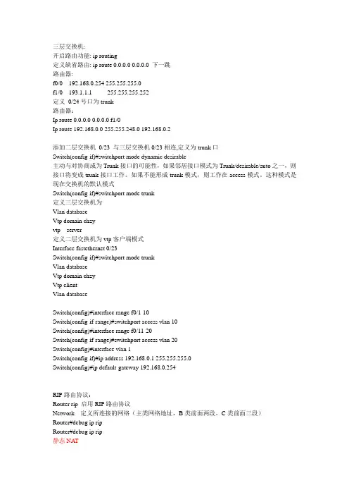
三层交换机:开启路由功能: ip routing定义缺省路由: ip route 0.0.0.0 0.0.0.0 下一跳路由器:f0/0 192.168.0.254 255.255.255.0f1/0 193.1.1.1 255.255.255.252定义0/24号口为trunk路由器:Ip route 0.0.0.0 0.0.0.0 f1/0Ip route 192.168.0.0 255.255.248.0 192.168.0.2添加二层交换机0/23 与三层交换机0/23相连,定义为trunk口Switch(config-if)#switchport mode dynamic desirable主动与对协商成为Trunk接口的可能性,如果邻居接口模式为Trunk/desirable/auto之一,则接口将变成trunk接口工作。
如果不能形成trunk模式,则工作在access模式。
这种模式是现在交换机的默认模式Switch(config-if)#switchport mode trunk定义三层交换机为Vlan databaseVtp domain chzyvtp server定义二层交换机为vtp客户端模式Interface fastethernet 0/23Switch(config-if)#switchport mode trunkVlan databaseVtp domain chzyVtp clientVlan databaseSwitch(config)#interface range f0/1-10Switch(config-if-range)#switchport access vlan 10Switch(config)#interface range f0/11-20Switch(config-if-range)#switchport access vlan 20Switch(config)#interface vlan 1Switch(config-if)#ip address 192.168.0.1 255.255.255.0Switch(config)#ip default-gateway 192.168.0.254RIP路由协议:Router rip 启用RIP路由协议Network 定义所连接的网络(主类网络地址,B类前面两段,C类前面三段)Router#debug ip ripRouter#debug ip rip静态NAT将使用公网地址的机器映射到内部网络上,实现一一映射定义内部接口和外部接口Router(config)#interface f 0/0Router(config-if)#ip nat insideRouter(config-if)#exitRouter(config)#interface f 0/1Router(config-if)#ip nat outsideRouter(config)#ip nat inside source static 192.168.0.1 218.22.229.122Router(config)#ip route 0.0.0.0 0.0.0.0 f0/1静态NAPT实现端口映射ip nat inside source static tcp 192.168.0.3 80 218.22.229.122 80ip nat inside source static tcp 192.168.0.2 21 218.22.229.122 21动态NAPT实现内部私有地址访问外部公有地址,即内部私有地址机器与外部某一个公网地址(路由器接口地址)的某一端口映射Router(config)#interface f 0/0Router(config-if)#ip nat insideRouter(config-if)#exitRouter(config)#interface f 0/1Router(config-if)#ip nat outsideAccess-list 访问列表号permit 内部网络号掩码反码Ip nat pool 地址池名外部地址范围netmask 子网掩码Ip nat inside source list 访问控制列表号pool 地址池名overload(反复复用)或者Ip nat inside source list 访问控制列表号interface 外部接口overloadip route 0.0.0.0 0.0.0.0 FastEthernet1/0ip route 192.168.0.0 255.255.248.0 192.168.0.2ip route 194.1.1.0 255.255.255.0 193.1.1.2access-list 1 permit 192.168.0.0 0.0.7.255Router(config)#ip nat inside source list 1 interface f1/0 overload或者:Router(config)#ip nat pool isp 193.1.1.1 193.1.1.1 netmask 255.255.255.0Router(config)#ip nat inside source list 1 pool isp overload内部本地:192.168.1.2内部全局:内部对外公开的公网地址193.1.1.1动态NAPT:ip nat pool isp 193.1.1.3 193.1.1.4 netmask 255.255.255.0ip nat inside source list 1 pool isp overloadip nat inside source static 192.168.1.3 193.1.1.5标准访问控制列表:Access-list 规则序号permit/deny address wildcard-mask规则序号为1~99应用访问控制列表:进入接口Ip access-group 规则序号out(in)经端口流出设备时做访问控制,是out应用经设备外的数据端口流入设备时做访问控制,是in应用例:Router(config)#access-list 1 deny 192.168.1.0 0.0.0.255Router(config)#access-list 1 permit 192.168.3.0 0.0.0.255Router#sh access-lists 1Standard IP access list 1deny 192.168.1.0 0.0.0.255permit 192.168.3.0 0.0.0.255应用访问控制列表到接口上Router(config)#int e1/0Router(config-if)#ip accRouter(config-if)#ip access-group 1 out编号扩展访问控制列表规则编号为100~199Access-list 列表号{permit|deny} protocol source(源地址) 源掩码反码目的地址目的掩码反码端口范围端口范围:eq(=) gt(>) lt(<) neq(!=) range(范围)应用于端口方向:1、控制由外到内的数据包的时候,可以用IN,反之则用OUT2、标准访问控制列表应用接口靠近目的地址端,扩展访问控制列表应用靠近源地址端注:在访问控制列表中,当找不到匹配规则,则默认是拒绝查看:Router#show ip access-lists 101清除ACL: no ip access-list extended 101(编号) 包括命名访问控制列表或no access-list 101 只能删除编号的访问控制列表命名访问控制列表:例:Router(config)#ip access-list extended denystudentwwwRouter(config-ext-nacl)#deny tcp 192.168.2.2 0.0.0.0 194.1.1.2 0.0.0.0 eq wwwRouter(config-ext-nacl)#permit tcp 192.168.1.2 0.0.0.0 194.1.1.2 0.0.0.0 eq wwwRouter(config-ext-nacl)#permit ip any anyRouter(config-ext-nacl)#end%SYS-5-CONFIG_I: Configured from console by consoleRouter#conf tEnter configuration commands, one per line. End with CNTL/Z.Router(config)#int f0/0Router(config-if)#ip access-group denystudentwww inRouter(config-if)#end命名的标准访问控制列表:Router(config)#ip access-list standard {name}deny {源掩码反码|源主机|any} 或permit {源掩码反码|源主机|any}应用于接口Cisco-dhcp配置Router(config)#ip dhcp pool pool1Router(dhcp-config)#network ?A.B.C.D Network number in dotted-decimal notationRouter(dhcp-config)#network 192.168.2.0 255.255.255.0 //设置分配地址的网络号Router(dhcp-config)#dns ?A.B.C.D Set ip address of DNS serverRouter(dhcp-config)#dns 202.102.192.68 //设置DNSRouter(dhcp-config)#defRouter(dhcp-config)#default-router 192.168.2.1 //设置网关Router(dhcp-config)#exitRouter(config)#ip dhcp exRouter(config)#ip dhcp excluded-address 192.168.2.1 ? //设置排除A.B.C.D High IP address<cr>Router(config)#ip dhcp excluded-address 192.168.2.1 192.168.2.10PPP认证:encapsulation ppp 在接口下封装pppppp authentication chap 启动ppp验证并指定为ppp chap验证方式username username password (0|7) password如:username rb password 0 111以对方路由器的名称作为用户名双方密码相同,0表示非密文,7表示密文在DCE端配置时钟为64000注:被验证方发送自己的主机名作为ppp用户名,chap协商由验证方发起,被验证方不需要启动ppp验证验证:sh int s0/0诊断:debug ppp authentication帧中继网:两种虚电路:PVC 永久虚电路SVC 交换式虚电路DLCI:数据链路连接标识符,用于标识DTE设备,一般由帧中继服务商提供,用于区分网络上不同的虚电路路由器DTE:数据终端设备Cloud0 DCE:数据电路终端设备LMI:帧中继本地管理接口帧中继技术提供面向连接的数据链路层的通信,在每对设备之间都存在一条定义好的通信链路,且该链路有一个链路识别码R1(config-if)#encapsulation frame-relay 帧中继封装R1(config-if)#frame-relay lmi-type cisco 帧中继类型为cisco/ansi/q933aR1(config)#int s1/0.1 point-to-point 配置子端口,并设置为点对点模式R1(config-subif)#ip add 192.168.1.1 255.255.255.0 分配子端口ip地址R1(config-subif)#frame-relay interface-dlci 102 指定点对点对应的DLCI值测试:Show frame-delay lmi/map/pvcPVC:列出所有配置的PVC和DLCI号,提供每个PVC连接的状态和流量统计Map:显示网络层到DLCI的映射Lmi:显示本地路由器和帧中继交换机之间的交换的LMI流量统计Router#sh interfaces s1/0诊断:debug frame-relay lmiVPN1、配置IKEIDE:internet密钥交换,提供IPSEC对等体验证,协商IPSEC密钥和协商IPSEC安全关联IPSEC:internet协议安全性Crypto isakmp enable 启动isakmpCrypto isakmp policy 10 //建立IKE策略,优先级为10authentication pre-share 使用预共享的密码进行身份验证,另外有rsa-encr(RSA加密)和RSA-sig(RSA签名)encryption 3des //使用3des加密方式3des:指三倍的数据加密标准DES:数据加密标准AES:高级加密标准hash md5 //指定hash算法为md5 sha(完整性算法)2、配置keyscrypto isakmp key tom address 200.1.1.2 //设置要使用的预定义密钥为tom,指定vpn另一端路由器IP地址为200.1.1.23、配置IPSECcrypto ipsec transform-set jizhen esp-3des esp-md5-hmac// 创建一个交换集,交换数据被md5保护,jizhen为交换集名字4、配置IPSEC加密映射crypto map tom 10 ipsec-isakmp //创建加密图,使用isakmp建立ipsec sa,以保护当前加密映射的指定数据库set peer 200.1.1.2 //标识对方路由器IP地址,指定对等体set transform-set jizhen //指定加密图使用IPSEC交换集match address 101 //用ACL来定义加密的通信access-list 101 permit ip 192.168.1.0 0.0.0.255 192.168.2.0 0.0.0.255 //定义ACL,并用ACL来定义加密的通信5、应用加密图到接口int f 0/0crypto map tom验证:Show crypto ip saDebug crypto ip(isakmp)Show crypto isakmp sa (IKE阶段1)Show crypto ipsec sa (建立ipsec数据连接)Sh crypto map无线网配置:3560交换机划分了三个vlan0/1接vlan2 192.168.1.0 无线路由器的E1口接vlan2 0/2接vlan3 192.168.2.0 AP接vlan30/5接vlan1 192.168.0.0 pc2接vlan1 作为有线网络无线路由器:点击save settings保存设置PC机:三层交换机设置:划分vlan设置vlan接口地址interface Vlan1ip address 192.168.0.1 255.255.255.0 interface Vlan2ip address 192.168.1.1 255.255.255.0 interface Vlan3ip address 192.168.2.1 255.255.255.0 设置DHCPip dhcp excluded-address 192.168.0.1 ip dhcp excluded-address 192.168.0.254 ip dhcp excluded-address 192.168.1.1 ip dhcp excluded-address 192.168.1.254 ip dhcp excluded-address 192.168.2.1 !ip dhcp pool dhcpnetwork 192.168.0.0 255.255.255.0 default-router 192.168.0.1dns-server 61.139.2.69ip dhcp pool vlan2network 192.168.1.0 255.255.255.0 default-router 192.168.1.1dns-server 192.168.1.1ip dhcp pool vlan3network 192.168.2.0 255.255.255.0 default-router 192.168.2.1dns-server 192.168.2.1 ip routing。

三层交换机与路由器的配置实例(图解)本文档旨在提供关于如何配置三层交换机与路由器的详细指南,并附有具体实例和图解。
下面将按照章节细化介绍。
1.交换机与路由器的基本概念及作用
1.1 交换机的作用与工作原理
1.2 路由器的作用与工作原理
2.三层交换机与路由器的区别与联系
2.1 三层交换机的特点和应用场景
2.2 路由器的特点和应用场景
3.三层交换机与路由器的配置前准备
3.1 设备检查与准备
3.2 网络规划与拓扑设计
4.三层交换机的配置步骤
4.1 连接与登录交换机
4.2 设置管理IP地质
4.3 配置VLAN
4.4 配置三层交换机的IP路由功能
5.路由器的配置步骤
5.1 连接与登录路由器
5.2 设置管理IP地质
5.3 配置静态路由
5.4 配置动态路由协议
6.三层交换机与路由器的互通配置
6.1 网络互通的基本原理
6.2 配置路由器与交换机之间的互联
6.3 配置路由器与其他网络设备的互联
7.实际案例分析与图解
7.1 案例一:简单局域网互通配置
7.2 案例二:跨网段通信配置
7.3 案例三:路由器的互联配置
附件:
本文档不涉及附件内容。
法律名词及注释:
1.三层交换机:三层交换机(Layer 3 Switch)是一种将交换机和路由器两者功能集成在一起的网络设备。
它具备交换机的高速交换与路由器的一些路由功能。
2.路由器:路由器(Router)是用于将数据包在互联网络中转发的网络设备。
它根据目的地IP地质来决定下一跳的路径,实现网络间的通信。

第14章在三层交换机上配置路由协议三层交换机上配置路由协议一、实验目的:掌握三层接口的概念;在三层交换机上配置路由协议的方法;二、实验拓扑:拓扑图说明:1.设备:三台三层交换机S1,S2,S3;两台二层交换机S1,S3;四台PC;2.任务:A.三层交换机上配置EIGRP协议,实现网络互通;B.分别在两个二层交换机上划分两个VLAN,PC机分别划进不同的VLAN内。
三、实验步骤:(1)在二层交换机上创建VLAN,并把PC机划分进相应的VLAN内。
此处假设S1创建了VLAN 2,3 。
S3上创建了VLAN 3,4。
(注意此处VLAN间IP地址的规划)(2)在三层交换机上启用三层接口,并配置IP地址。
S1:S1(config)#vlan 2S1(config)#intvlan 2S1(config-if)#ip add 192.168.1.1 255.255.255.128S1(config)#intvlan3S1(config-if)#ip add 192.168.1.129 255.255.255.128 S1(config)#int port-channel 1S1(config-if)#no switchportS1(config-if)#ip add 192.168.4.1 255.255.255.0S1(config)#intf0/22S1(config-if)#no switchportS1(config-if)#ip add 192.168.5.1 255.255.255.0S2:S2(config)#vlan3S2(config)#vlan4S2(config)#intvlan3S2(config-if)#ip add 192.168.2.1 255.255.255.128S2(config)#intvlan4S2(config-if)#ip add 192.168.2.129 255.255.255.128 S2(config)#int port-channel 2S2(config-if)#no switchportS2(config-if)#ip add 192.168.4.2 255.255.255.0S2(config)#int f0/22S2(config-if)#no switchportS2(config-if)#ip add 192.168.6.2 255.255.255.0S3:S3(config)#intloop 3S3(config-if)#ip add 192.168.3.3 255.255.255.0S3(config)#int f0/1S3(config-if)#no switchportS3(config-if)#ip add 192.168.5.3 255.255.255.0S3(config-if)#no switchportS3(config-if)#ip add 192.168.6.3 255.255.255.0 (3) 创建链路汇聚S1:S1(config)#int range f0/23-24S1(con fig-if-range)#no switchportS1(con fig-if-range)#channel-group 1 mode onS2: 同上(3)在三层交换机上开启路由功能:ip routing此时,理论上哪些机器能够通信,检查能够通信的机器!!(4) 在三层交换机上配置EIGRP协议。