VHDL多功能数字钟
- 格式:doc
- 大小:217.50 KB
- 文档页数:21
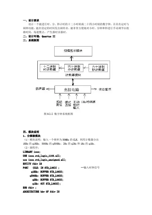
一、设计要求设计一个能进行时、分、秒计时的十二小时制或二十四小时制的数字钟,并具有定时与闹钟功能,能在设定的时间发出闹铃音,能非常方便地对小时、分钟和秒进行手动调节以校准时间,每逢整点,产生报时音报时。
二、设计环境:Quartus II三、系统框图四、模块说明1、分频器模块(1)模块说明:输入一个频率为50MHz 的CLK,利用计数器分出1KHz 的q1KHz,500Hz 的q500Hz,2Hz 的q2Hz 和1Hz 的q1Hz。
(2)源程序:LIBRARY ieee;USE ieee.std_logic_1164.all;use ieee.std_logic_unsigned.all;ENTITY fdiv ISPORT (CLK:IN STD_LOGIC ;--输入时钟信号q1KHz:BUFFER STD_LOGIC;q500Hz:BUFFER STD_LOGIC;q2Hz:BUFFER STD_LOGIC;q1Hz:OUT STD_LOGIC);END fdiv ;ARCHITECTURE bhv OF fdivIS图4-1-1数字钟系统框图BEGINP1KHZ:PROCESS(CLK)VARIABLE cout:INTEGER:=0;BEGINIF CLK'EVENT AND CLK='1'THENcout:=cout+1;--每来个时钟上升沿时cout开始计数IF cout<=25000THEN q1KHz<='0';--当cout<=25000时,q1KHz输出“0”ELSIF cout<50000THEN q1KHz<='1';--当25000<cout<=50000时,q1KHz ELSE cout:=0;--输出“1”,完成1KHz频率输出END IF;END IF;END PROCESS;P500HZ:PROCESS(q1KHz)--q1KHz作为输入信号,分出q500Hz VARIABLE cout:INTEGER:=0;BEGINIF q1KHz'EVENT AND q1KHz='1'THENcout:=cout+1;IF cout=1THEN q500Hz<='0';--二分频ELSIF cout=2THEN cout:=0;q500Hz<='1';END IF;END IF;END PROCESS;P2HZ:PROCESS(q500Hz)VARIABLE cout:INTEGER:=0;BEGINIF q500Hz'EVENT AND q500Hz='1'THENcout:=cout+1;IF cout<=125THEN q2Hz<='0';ELSIF cout<250THEN q2Hz<='1';ELSE cout:=0;END IF;END IF;END PROCESS;P1HZ:PROCESS(q2Hz)VARIABLE cout:INTEGER:=0;BEGINIF q2Hz'EVENT AND q2Hz='1'THENcout:=cout+1;IF cout=1THEN q1Hz<='0';ELSIF cout=2THEN cout:=0;q1Hz<='1';END IF;END IF;END PROCESS;END bhv;(3)模块图:2、控制器模块(1)模块说明:输入端口enset,k,set键来控制6个状态,这六个状态分别是显示计时时间状态,调计时的时、分、秒状态,调闹铃的时、分的状态,reset键是复位键,用来回到显示计时时间的状态。
VHDL语言数字时钟论文-基于FPGA的具有闹钟和校时功能的数字钟设计实验名称:基于FPGA的具有闹钟和校时功能的数字钟设计一、设计内容和要求实验要求使用 VHDL进行多功能时钟的设计具体要求如下:1.能将基本的小时、分钟、及秒钟显示在数码管上。
2(能利用拨码开关进行时间的校正。
3.具有整点报时和闹钟的功能。
二、 FPGA简介以硬件描述语言,Verilog或VHDL,所完成的电路设计~可以经过简单的综合与布局~快速的烧录至 FPGA 上进行测试~是现代 IC设计验证的技术主流。
这些可编辑元件可以被用来实现一些基本的逻辑门电路,比如AND、OR、XOR、NOT,或者更复杂一些的组合功能比如解码器或数学方程式。
在大多数的FPGA里面~这些可编辑的元件里也包含记忆元件例如触发器,Flip,flop,或者其他更加完整的记忆块。
FPGA采用了逻辑单元阵列LCA,Logic Cell Array,这样一个概念~内部包括可配臵逻辑模块CLB,Configurable Logic Block,、输入输出模块IOB,Input Output Block,和内部连线,Interconnect,三个部分。
现场可编程门阵列,FPGA,是可编程器件~与传统逻辑电路和门阵列,如PAL~GAL及CPLD器件,相比~FPGA具有不同的结构。
FPGA利用小型查找表,16×1RAM,来实现组合逻辑~每个查找表连接到一个D触发器的输入端~触发器再来驱动其他逻辑电路或驱动I/O~由此构成了既可实现组合逻辑功能又可实现时序逻辑功能的基本逻辑单元模块~这些模块间利用金属连线互相连接或连接到I/O模块。
FPGA的逻辑是通过向内部静态存储单元加载编程数据来实现的~存储在存储器单元中的值决定了逻辑单元的逻辑功能以及各模块之间或模块与I/O间的联接方式~并最终决定了FPGA所能实现的功能~FPGA允许无限次的编程。
FPGA基本特点采用FPGA设计ASIC电路(专用集成电路,~用户不需要投片生产~就能得到合用的芯片。
1 摘要本文介绍了利用VHDL硬件描述语言设计的多功能数字钟的思路和技巧。
本设计是一个多功能数字钟,具有计时、校时、清零等简单功能,在QuartusII 开发环境中编译和仿真了所设计的程序,并在可编程逻辑器件(ALTEA EPM7064SLI44-7)上下载验证。
关键字:QuartusII,数字钟, ALTEA EPM7064SLI44-7,VHDL2 引言随着电子设计自动化(EDA)的高速发展,电子系统的设计技术和工具发生了深刻的变化。
EDA的关键技术之一是要求用形式化方式来描述数字系统的硬件电路,即要用所谓硬件描述语言来描述硬件电路。
本文即介绍如何利用VHDL硬件描述语言设计一个具有时、分、秒计时显示、调整时间功能的数字钟,并且利用QuartusII开发环境进行编译、仿真,最终下载到可编程逻辑器件FPGA上进行验证。
3 实验要求设计制作一个多功能计时器,设计要求如下:1.计时功能:数字钟以24个小时为一个周期,必须显示时、分、秒。
2.清零功能:在板上设置一个手动清零开关,通过它可以对电路实现实时的手动清零。
3.校时功能:可随时对电路进行校时功能,并设置两个开关(a/b)控制。
按下a开关时(手不松开),数字时钟的秒钟数迅速增加(4HZ的时钟频率来驱动),并按60循环,计满60后再回00。
按下b开关时(手不松开),数字时钟的分钟数迅速增加(4HZ的时钟频率来驱动),并按60循环,计满60后再回00。
4 系统原理框图数字时钟实际上是一个对标准1Hz进行计时的计数电路,秒计数器满60后向分计数器进位,分计数器满60后向时计数器进位,时计数器按24翻1规律计数,计数输出经译码器送LED显示器,由于计数的起始时间不可能与标准时间一致,故需要在电路上加上一个校时电路。
5 各功能实现原理整个数字钟的设计包括七个模块,分别为分频、清零、计时、校时、BCD编码、扫描、译码,各模块的设计解决方案具体如下。
5.1 分频功能实现因为我们需要1HZ的频率来用来驱动秒计时器,而硬件提供的时钟频率是4HZ,所以我们要进行分频。
一、数字钟要求:1、能进行正常的时、分、秒计时功能,分别由6个数码管显示24h、60min、60s。
2、可以进行当前时间设置。
二、应用系统功能的详细说明该数字钟使用的是二十四时计时制。
计时时间范围从00:00:00到23:59:59。
当时间及时到23:59:59时,钟面跳转到00:00:00重新下一轮计时。
该数字钟总共有三个按钮,分别是md1控制数字钟的开关,md2(1)控制数字钟的正常运行还是时间设置和md2(0)控制对时还是对分的设置。
md1:为0时,数字钟电源关闭;为1时,数字钟电源开启。
md2(1):为0时,数字钟正常运行;为1时,数字钟进入设置状态。
md2(0):为0时,数字钟对时进行设置;为1时,数字钟对分进行设置。
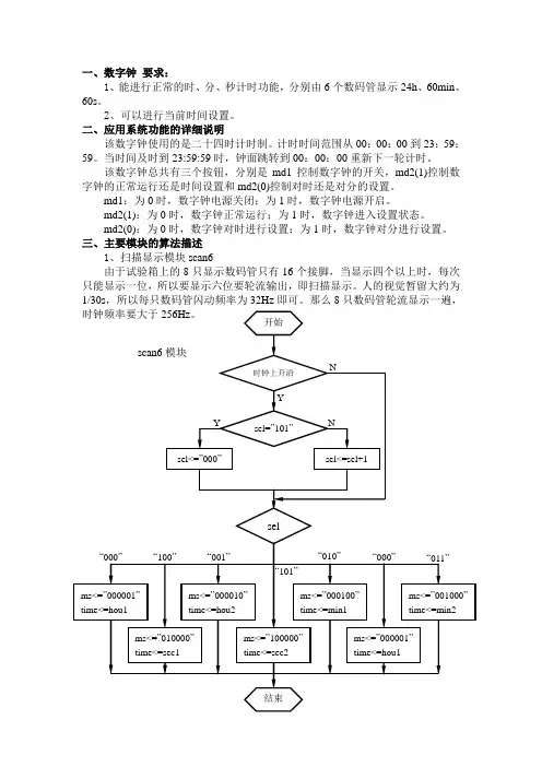
三、主要模块的算法描述1、扫描显示模块scan6由于试验箱上的8只显示数码管只有16个接脚,当显示四个以上时,每次只能显示一位,所以要显示六位要轮流输出,即扫描显示。
人的视觉暂留大约为1/30s,所以每只数码管闪动频率为32Hz即可。
那么8只数码管轮流显示一遍,2、计时模块hourten,huoroen,minten,minone,secten,secone计时模块共分为6个部分,分别是时、分、秒的十位和个位。
由每位之间的逻辑关系以及md1和md2来控制正常计数、进位和对小时分钟的设置。
3、译码模块dec7s把计时模块输出的时、分、秒各位的二进制数翻译成能在七段数码管上显示的七位二进制码,能够显示0~9各个数字。
四、程序的源代码清单library ieee;use ieee.std_logic_1164.all;use ieee.std_logic_unsigned.all;entity digital_clock isport(clk:in std_logic; --扫描频率,>=256Hz clk1:in std_logic; --计时频率,1Hzmd1:in std_logic; --开关,0时有效md2:in std_logic_vector(1 downto 0); --时间设置dout:out std_logic_vector(6 downto 0); --译码显示ms:out std_logic_vector(5 downto 0)); --扫描控制end digital_clock;architecture one of digital_clock issignal sel:std_logic_vector(2 downto 0);signal hou1,hou2,min1,min2,sec1,sec2:std_logic_vector(3 downto 0);signal time:std_logic_vector(3 downto 0);begin---------------------------------------------scan6scan6:process(clk1,hou1,hou2,min1,min2,sec1,sec2)beginif clk1'event and clk1='1' thenif sel="101" thensel<="000";elsesel<=sel+1;end if;end if;case sel iswhen "000"=>ms<="000001";time<=hou1;when "001"=>ms<="000010";time<=hou2;when "010"=>ms<="000100";time<=min1;when "011"=>ms<="001000";time<=min2;when "100"=>ms<="010000";time<=sec1;when "101"=>ms<="100000";time<=sec2;when others=>ms<="100000";time1=sec2;end case;end process scan6;---------------------------------------------hourtenhourten:process(clk,hou2,min1,min2,sec1,sec2,md1,md2)beginif clk'event and clk='1' thenif (hou1&hou2&min1&min2&sec1&sec2="001000110101100101011001") then hou1<="0000"; --当23:59:59时,时十位归0elsif (hou1&hou2="00100011"and md1&md2="001") thenhou1<="0000"; --当设置小时,时位是23时,时十位归0elsif ((hou2&min1&min2&sec1&sec2="10010101100101011001")or(hou2="1001"and md1&md2="001")) thenhou1<=hou1+1; --当正常计时,时间是x9:59:59时,或设置小时,end if; --时位是x9时,时十位加1end if;end process hourten;---------------------------------------------houronehourone:process(clk,min1,min2,sec1,sec2,md1,md2,hou1)beginif clk'event and clk='1' thenif (hou1&hou2&min1&min2&sec1&sec2="001000110101100101011001") then hou2<="0000"; --当23:59:59时,时个位归0elsif (hou2&min1&min2&sec1&sec2="001000110101100101011001") thenhou2<="0000"; --当x9:59:59时,时个位归0elsif ((hou2="1001"or hou1&hou2="00100011")and(md1&md2="001")) thenhou2<="0000"; --当设置小时,时位是x9或23时,时个位归0 elsif (min1&min2&sec1&sec2="0101100101011001)or(md1&md2="001")then hou2<=hou2+1; --当正常计时,时间是xx:59:59时,或设置小时,时个位加1 end if;end if;end process hourone;---------------------------------------------mintenminten:process(clk,min2,sec1,sec2,md1,md2)beginif clk'event and clk='1' thenif (min1&min2&sec1&sec2="0101100101011001") thenmin1<="0000"; --当xx:59:59时,分十位归0elsif (min1&min2="01011001"and md1&md2="000")thenmin1<="0000"; --当设置分钟,分位是59时,分十位归0elsif (min2&sec1&sec2="100101011001")or --正常计时,时间是xx:x9:59时,或(min2="1001"and md1&md2="000") then --设置分钟,时间是x9,分十位加1min1<=min1+1;end if;end if;end process minten;---------------------------------------------minoneminone:process(clk,sec1,sec2,md1,md2)beginif clk'event and clk='1' thenif (min2&sec1&sec2="100101011001") thenmin2<="0000"; --当xx:x9:59时,分个位归0elsif (min2="1001"and md1&md2="000") thenmin2<="0000"; --当设置分钟,分位是x9时分个位归0elsif (sec1&sec2="01011001")or(md1&md2="000") thenmin2<=min2+1; --正常计时,时间是xx:xx:59时,或设置分钟,分个位加1 end if;end if;end process minone;---------------------------------------------sectensecten:process(clk)beginif clk'event and clk='1' thenif (sec1&sec2="01011001") then --当时间是xx:xx:59时,秒十位归0sec1<="0000";elsif sec2="1001"then --当秒位是x9时,秒十位加1sec1<=sec1+1;end if;end if;end process secten;--------------------------------------------seconesecone:process(clk)beginif clk'event and clk='1' thenif sec2="1001" then --当秒位是x9时,秒个位归0sec2<="0000";else sec2<=sec2+1; --否则加1end if;end if;end process secone;------------------------------------------dec7sdec7s:process(time)begincase time iswhen "0000"=>dout<="0111111";when "0001"=>dout<="0000110";when "0010"=>dout<="1011011";when "0011"=>dout<="1001111";when "0100"=>dout<="1100110";when "0101"=>dout<="1101101";when "0110"=>dout<="1111101";when "0111"=>dout<="0000111";when "1000"=>dout<="1111111";when "1001"=>dout<="1101111";when others=>dout<="0111111";end case;end process dec7s;end one;。
EDA期末作业班级:020914(一)选题目的学习使用QuartusII 9.0,巩固已掌握的EDA知识,增强自己的动手实践能力。
(二)设计目标实现多功能数字钟的设计,主要有以下功能:①计时,并且可以24小时制和12小时制转换。
②闹钟③整点报时④秒表(三)实现方案该课题的实现过程大体如下:先对4MHZ的信号进行分频使其变为1HZ;将该信号加入计数器中(模60和模24/12)实现基本时钟功能;然后在此基础上加入闹钟,秒表,整点报时,24/12小时制转换模块;最后在动态显示电路中实现上述功能。
(四)设计过程、模块仿真及实现结果一、分频器分频器的VHDL语言为(4M分频)library ieee;use ieee.std_logic_1164.all;use ieee.std_logic_unsigned.all;entity fenpinqi isport(clk_in : in std_logic;clk_out : out std_logic);end fenpinqi;architecture behivor of fenpinqi issignal cou : std_logic_vector(21 downto 0);beginprocess(clk_in)beginif clk_in'event and clk_in='1' thencou<=cou+1;end if;end process;process(cou)beginclk_out<=cou(21);end process;end architecture behivor;完成4Mhz到1hz的转换仿真结果略。
二、计时器(模60,模24,模12)模60设计的电路图如下模24/12计数器如下合成模块分别如下仿真波形如下M60波形分析:ql[3..0]从0变到9,qh[3..0]从0变到5,当clk经过60个周期后,co输出一个脉冲。
摘要VHDL作为一种硬件描述语言,可用于数字电路与系统的描述、模拟和自动设计与仿真等,是当今电子设计自动化的核心技术。
本文使用VHDL语言设计了一个数字时钟电路,给出了设计该数字系统的流程和方法。
本设计方法具有硬件描述能力强,设计方法灵活,便于修改等优点,大大降低了数字系统设计的难度,提高了工作效率。
本设计采用EDA技术,以硬件描述语言VHDL为系统逻辑描述手段设计文件,在MAX+PlusⅡ工具软件环境下,采用自顶向下的设计方法,由各个基本模块共同构建了一个基于CPLD的数字钟。
系统主芯片采用EPM7128SLC84,由时钟模块、控制模块、计时模块、数据译码模块、显示以及报时模块组成。
经编译和仿真所设计的程序,在可编程逻辑器件上下载验证,本系统能够完成时、分、秒的分别显示,由按键输入进行数字钟的校时、清零、启停功能。
关键词:硬件描述语言,VHDL,数字电路设计, 数字钟Digital Clock Design Based On The Hardware DescriptionLanguage(VHDL)Author: 。
Tutor: 。
AbstractVHDL can be used to describe,simulate and digital system automatically. Nowdays,it becomes a key technology in automatic electronic design. There is a lot of superiority in this description language.This article introduces the method and the process using VHDL to design a digital system by an example of digital clock dasign. The result given in this paper shows that VHDL is one of the strongest tools in hardware description and it is a flexible among the design method. The method given in this paper can reduce the difficulty of digital system design and improve the work efficiency.The use of EDA design technology, hardware-description language VHDL description logic means for the system design documents, in MaxplusII tools environment, a top-down design, by the various modules together build a CPLD-based digital clock.The main system chips used EPM7128SLC84, make up of the clock module, control module, time module, data decoding module, display and broadcast module. After compiling the design and simulation procedures, the programmable logic device to download verification, the system can complete the hours, minutes and seconds respectively, using keys to modify, cleared , start and stop the digital clock.Key words: Hardware description language,VHDL, Digital circuit design, digital clock目录1 绪论 (1)1.1课题背景 (1)1.2本课题研究的内容 (1)2 总体设计方案 (3)3 单元模块电路设计 (4)3.1时间显示电路模块设计 (4)3.2按键及指示灯电路模块的设计 (5)3.3蜂鸣器及有源晶振电路的设计 (7)3.4CPLD编程下载电路的设计 (8)3.5电源电路的设计 (9)3.5.1变压器次级电压估算 (9)3.5.2 变压器输入功率的计算 (9)3.5.3 滤波电容参数的选取 (10)3.6EPM7128SLC84器件介绍 (10)4 CPLD 编程设计 (11)4.1系统信号的定义及顶层模块 (11)4.2时钟节拍产生模块 (12)4.3模式选择功能模块 (14)4.4快速时间设置功能模块 (16)4.5秒、分、时计时与时间调整模块 (16)4.6闹铃时间设置模块 (18)4.7闹铃与整点报时模块 (19)4.8七段显示译码模块 (20)4.9LED显示模块 (22)5 系统功能仿真 (25)5.1时钟节拍产生模块的仿真波形 (25)5.2模式选择功能模块的仿真波形 (26)5.3闹铃设置功能模块的仿真波形 (27)5.4七段译码功能模块的仿真波形 (28)5.5LED显示功能模块的仿真波形 (30)5.6系统总体功能仿真波形 (31)总结 (32)致谢 (33)参考文献 (34)附录A:基于CPLD的多功能数字钟电路图 (35)附录B:基于VHDL语言的时、分、秒等电路的源码 (36)1绪论1.1 课题背景我们已经进入了数字化和信息化的时代,其特点是各种数字产品的广泛应用。
多功能数字钟报告及VHDL源程序一、系统功能概述功能描述;1.完成秒/分/时的依次显示并正确计数;2.实现整点报时,有扬声器发出报时声音;3.时间设置,在计时状态下按下set键,进入校时状态,再按下s1键实现秒校验,按下s2键实现分计时,按下s3键实现时校验。
4.实现12/24小时转换,按下change键,进入24小时计时;二、系统组成以及系统各部分的设计1、系统结构描述本设计未采用模块构成电路图结构,也未用顶层文件,而由简单的vhdl语句构成.。
首先,进入进程后由if语句判断启动键是否有效,当启动键有效时,再判断秒校时键是否有效,然后依次判断分校时,时校时。
当校时键有效时,时间设置按脉冲依次计时,到设置值后断开校时键,最后断开启动校时键,即实现时间的设置。
计时功能由if语句嵌套实现,外层实现秒计时,内层依次实现分计时,时计时。
最后将变量值传给输出端口。
整点报时功能的实现,通过判断时、分、秒高低位都为0来输出高电位,否者,输出低电位。
2.设计源程序library ieee;use ieee.std_logic_1164.all;use ieee.std_logic_unsigned.all;entity shuzizhong isport(clk,set,change,s1,s2,s3:in std_logic;second1,second2,minite1,minite2,hour1,hour2:out std_logic_vector(3 downto 0); cout:out std_logic);end entity;architecture one of shuzizhong isbeginpro1:process(clk,set,s1,s2,s3,change)variablemsecond1,msecond2,mminite1,mminite2,mhour11,mhour12,mhour21,mhour22:std_logic_vecto r(3 downto 0);beginif clk'event and clk='1' thenif set='1' then -----启动校验if s1='1'then msecond1:=msecond1+1;if msecond1="1010"then msecond1:="0000";msecond2:=msecond2+1;if msecond2="0110"then msecond2:="0000";end if;end if;end if; --------秒校验if s2='1'thenmminite1:=mminite1+1;if mminite1="1010"then mminite1:="0000";mminite2:=mminite2+1;if mminite2="0110"then mminite2:="0000";end if;end if;end if; ---------分校验if s3='1' thenmhour11:=mhour11+1;mhour21:=mhour21+1;if mhour11="1010" then mhour11:="0000";mhour12:=mhour12+1;end if;if mhour11="0011" and mhour12="0001"then mhour11:="0001";mhour12:="0000"; end if;if mhour21="1010" then mhour21:="0000";mhour22:=mhour22+1;end if;if mhour21="0100"and mhour22="0010"thenmhour21:="0000";mhour22:="0000";end if;end if;-------时校验else msecond1:=msecond1+1;-----正常计时工作if msecond1="1010"then msecond1:="0000";msecond2:=msecond2+1;if msecond2="0110"then msecond2:="0000";mminite1:=mminite1+1;if mminite1="1010"then mminite1:="0000";mminite2:=mminite2+1;if mminite2="0110"then mminite2:="0000";mhour11:=mhour11+1;mhour21:=mhour21+1;if mhour11="1010" then mhour11:="0000";mhour12:=mhour12+1;end if;if mhour11="0011" and mhour12="0001"then mhour11:="0001";mhour12:="0000";end if;-------12小时制if mhour21="1010" then mhour21:="0000";mhour22:=mhour22+1;end if;if mhour21="0100"and mhour22="0010"then mhour21:="0000";mhour22:="0000";end if;----------24小时制end if;end if;end if;end if;if (msecond1="0000") and (msecond2="0000") and (mminite1="0000") and (mminite2="0000") then cout<='1';else cout<='0';end if;-----------整点报时end if;end if;second1<=msecond1;second2<=msecond2;minite1<=mminite1;minite2<=mminite2;if change='0' then hour1<=mhour11;hour2<=mhour12;else hour1<=mhour21;hour2<=mhour22;------12/24小时制转换end if;end process;end architecture one;---------结束2、系统以及各个模块的仿真波形1.整体计时波形图2.时间设置波形图3、下载时选择的开发系统模式以及管脚定义选择模式0表1 GW48-CK开发系统工作模式:三、课程设计过程中遇到的问题以及解决方法通过这次课程设计,我遇到了很多困难,开始自己尝试了数字锁,数字钟实验的编程,但总是与理想效果相去甚远,只有偶尔一个模块设计正确,为了体验这次程序的完整过程,最后不得不借用了同学的成功版本。
一、多功能手表的主模块设计:1、设计思想:由两大模块组成,按键控制模块(control)和时钟模块(clock),按键控制模块主要通过B1,B2 ,B3 三个按键的输入来控制时间的调整,闹钟时间的调整,以及打开闹钟,关闭闹钟的功能,时钟模块主要通过:一是输入的时钟信号clk 触发,clk运行一定的周期,秒就加一,秒有进位时,分加一,分有进位时,依次类推,进行时间的运行;当时间运行到与闹钟时间相同,闹铃信号ring变为1,持续30秒,变为零。
二是来自按键控制模块的时间增信号,inc_hrs,inc_min,inc_sec等信号,进行时间的调整,闹钟响的时候关闭闹钟。
以及其他功能。
2、输入、输出及中间信号说明:输入信号clk 时钟信号rst 复位信号B1 按键1B2 按键2B3 按键3输出信号hours 时间模式的小时minutes 时间模式的分钟seconds 时间模式的秒ahours 闹钟模式的小时aminutes 闹钟模式的分ring 闹钟响铃信号am_pm 时间模式的a.m 或者p.m指示(为0时表示a.m,为1时表示p.m)aam_pm 闹钟模式的a.m 或者p.m指示(为0时表示a.m,为1时表示p.m)disp_time1 显示时间模式的时、分、秒标志,为1时显示,为零时不显示disp_alarm 显示闹钟模式的时、分标志,为1时显示,为零时不显示中间信号:inc_hrs 时间模式的小时加1inc_min 时间模式的分钟加1inc_sec 时间模式的秒加1inc_ahrs 闹钟模式的小时加1inc_amin 闹钟模式的分钟加1alarm_off 时间模式下如果闹钟响,关闹钟信号set_alarm 闹钟模式下,开启关闭闹钟信号alarm_set 闹钟模式下设置闹钟信号S_hours 时间模式的小时hours寄存信号S_minutes 时间模式的分钟minutes寄存信号S_seconds 时间模式的秒seconds寄存信号S_ahours 闹钟模式的小时ahours寄存信号S_aminutes 闹钟模式的分钟aminutes寄存信号S_ring 闹钟模式的闹钟响铃ring寄存信号S_am_pm 时间模式的am_pm寄存信号S_aam_pm 闹钟模式的aam_pm寄存信号3、主程序代码:library IEEE;use IEEE.STD_LOGIC_1164.ALL;use ieee.numeric_bit.bit;use IEEE.STD_LOGIC_ARITH.ALL;use IEEE.STD_LOGIC_UNSIGNED.ALL;entity main isport(B1,B2,B3,clk,rst:in std_logic;hours,minutes,seconds,ahours,aminutes:out std_logic_vector(7 downto 0);ring,am_pm,aam_pm,disp_time1,disp_alarm:out std_logic);end main;architecture Behavioral of main iscomponent clock is ----时钟模块port(clk,rst,inc_hrs,inc_min,inc_sec,inc_ahrs,inc_amin,set_alarm,alarm_off:in std_logic;hours,ahours,minutes,aminutes,seconds: inout std_logic_vector(7 downto 0);am_pm,aam_pm,ring,alarm_set:inout std_logic);end component;component control is -----按键控制模块port(B1,B2,B3,clk,rst:in std_logic;alarm_off,set_alarm:inout std_logic;disp_time1,disp_alarm,inc_hrs,inc_min,inc_sec,inc_ahrs,inc_amin:out std_logic);end component;signal inc_hrs,inc_min,inc_sec,inc_ahrs,inc_amin,alarm_off,set_alarm,alarm_set:std_logic;signal S_hours,S_minutes,S_seconds,S_ahours,S_aminutes: std_logic_vector(7 downto 0); signal S_ring,S_am_pm,S_aam_pm:std_logic;begin-----按键控制,时钟运行模块,以及最后输出模块使用并发语句设计controllor: control port map(B1,B2,B3,clk,rst, alarm_off,set_alarm,disp_time1,disp_alarm,inc_hrs,inc_min,inc_sec,inc_ahrs,inc_amin);clock1: clock port map(clk,rst,inc_hrs,inc_min,inc_sec,inc_ahrs,inc_amin,set_alarm,alarm_off,S_hours,S_ahours,S_minutes,S_aminutes,S_seconds,S_am_pm,S_aam_pm,S_ring,alarm_set);hours<=S_hours;minutes<=S_minutes;seconds<=S_seconds;ahours<=S_ahours;aminutes<=S_aminutes;am_pm<=S_am_pm;aam_pm<=S_aam_pm;ring<=S_ring;end Behavioral;(1)综合电路图:5、按键控制模块说明:(1)状态转移图:(2)ASM图(3)信号说明:与前面重复的这里不再赘述present_state 当前状态next_state 下一个状态七个状态说明:time1 时间显示模式set_sec 调整时间的秒模式set_min, 调整时间的分钟模式set_hrs, 调整时间的小时模式alarm, 闹钟模式set_alarm_hrs, 调整闹钟的小时模式set_alarm_min 调整闹钟的分钟模式(4)程序代码library IEEE;use IEEE.STD_LOGIC_1164.ALL;--use ieee.numeric_bit.bit;use IEEE.STD_LOGIC_ARITH.ALL;use IEEE.STD_LOGIC_UNSIGNED.ALL;entity control isport(B1,B2,B3,clk,rst:in std_logic;alarm_off,set_alarm:inout std_logic;disp_time1,disp_alarm,inc_hrs,inc_min,inc_sec,inc_ahrs,inc_amin:out std_logic); end control;architecture Behavioral of control istype state is(time1,set_sec,set_min,set_hrs,alarm,set_alarm_hrs,set_alarm_min);signal present_state,next_state :state;beginprocess(clk,rst)beginif rst='1' then ------异步复位present_state<=time1;elsif(clk'event and clk='1')then ------采用时钟边沿触发present_state<=next_state;end if;end process;process(B1,B2,B3,present_state,rst) -----由按键控制的状态转换进程beginif rst ='1' then ---------------异步复位alarm_off<='0';set_alarm<='0';elsecase present_state iswhen time1=> ---------------时间显示----------inc_hrs<='0';inc_min<='0';inc_sec<='0';inc_ahrs<='0';inc_amin<='0';disp_time1<='1';disp_alarm<='0'; ----状态输出if B1='1' then next_state<=alarm;elsif B2='1' then next_state<=set_hrs;elsif B3='1' then alarm_off<=not alarm_off;next_state<=time1;else next_state<=time1;end if;when set_hrs=> --------------------------设置时间inc_min<='0';inc_hrs<='0';inc_sec<='0';inc_ahrs<='0';inc_amin<='0';disp_time1<='1';disp_alarm<='0';if B2='1' then next_state<=set_min;elsif B3='1' then inc_hrs<='1';next_state<=set_hrs;else next_state<=set_hrs;end if;when set_min=> -------------------设置分钟inc_hrs<='0';inc_min<='0';inc_sec<='0';inc_ahrs<='0';inc_amin<='0';disp_time1<='1';disp_alarm<='0';if B2='1' then next_state<=set_sec;elsif B3='1' then inc_min<='1';next_state<=set_min;else next_state<=set_min;end if;when set_sec=> -------------------------设置秒inc_hrs<='0';inc_min<='0';inc_sec<='0';inc_ahrs<='0';inc_amin<='0';disp_time1<='1';disp_alarm<='0';if B2='1' then next_state<=time1;elsif B3='1' then inc_sec<='1';next_state<=set_sec;else next_state<=set_sec;end if;when alarm => -----------------闹钟显示inc_hrs<='0';inc_min<='0';inc_sec<='0';inc_ahrs<='0';inc_amin<='0';disp_time1<='0';disp_alarm<='1';if B1='1' then next_state<=time1;elsif B2='1' then next_state<=set_alarm_hrs;elsif B3='1' then set_alarm<=not set_alarm;next_state<=alarm;else next_state<=alarm;end if;when set_alarm_hrs=> ---------------调整闹钟的小时inc_hrs<='0';inc_min<='0';inc_sec<='0';inc_amin<='0';inc_ahrs<='0';disp_time1<='0';disp_alarm<='1';if B2='1' then next_state<=set_alarm_min;elsif B3='1' then inc_ahrs<='1'; next_state<=set_alarm_hrs;else next_state<=set_alarm_hrs;end if;when set_alarm_min=> -------------------------调整闹钟的分钟inc_hrs<='0';inc_min<='0';inc_sec<='0';inc_ahrs<='0';inc_amin<='0';disp_time1<='0';disp_alarm<='1';if B2='1' then next_state<=alarm;elsif B3='1' then inc_amin<='1';next_state<=set_alarm_min;else next_state<=set_alarm_min;end if;end case;end if;end process;end Behavioral;6、时钟模块说明:信号说明:与前面重复的这里不再赘述,s59 秒有进位的标志信号(由59变为0时,s59<=’1’,否则为‘0’)m59 分钟有进位的标志信号(由59变为0时,s59<=’1’,否则为‘0’)inchrs 时间的小时加1的寄存信号incmin 时间的分钟加1的寄存信号incsec 时间的秒加1的寄存信号c99 时钟过了1s,自动发出的秒加1 的信号程序代码:library IEEE;use IEEE.STD_LOGIC_1164.ALL;use ieee.numeric_bit.bit;use IEEE.STD_LOGIC_ARITH.ALL;use IEEE.STD_LOGIC_UNSIGNED.ALL;entity clock isport(clk,rst,inc_hrs,inc_min,inc_sec,inc_ahrs,inc_amin,set_alarm,alarm_off:in std_logic;hours,ahours,minutes,aminutes,seconds: inout std_logic_vector(7 downto 0);am_pm,aam_pm,ring,alarm_set:inout std_logic);end clock;architecture Behavioral of clock iscomponent CTR_59 is -------模60计数器模块port(clk,inc,rst:in std_logic;dout :out std_logic_vector(7 downto 0);t59:out std_logic);end component;component CTR_12 is ----------模12计数器模块port(clk,inc,rst:in std_logic;dout :out std_logic_vector(7 downto 0);am_pm:inout std_logic);end component;signal s59,m59,inchrs,incmin,incsec,c99:std_logic :='0';signal alarm_ring_time:integer range 0 to 50;signal div100:integer range 0 to 100;beginsec1:CTR_59 port map(clk,incsec,rst,seconds,s59);min1:CTR_59 port map(clk,incmin,rst,minutes,m59);hrs1:CTR_12 port map(clk,inchrs,rst,hours,am_pm);incmin<=(s59 and c99)or inc_min;inchrs<=(m59 and s59 and c99)or inc_hrs;incsec<=c99 or inc_sec;alarm_min:CTR_59 port map(clk,inc_amin,rst,aminutes,open);alarm_hrs:CTR_12 port map(clk,in_ahrs,rst,ahours,aam_pm);c99<='1' when div100=199 else '0';-----clk频率为200Hz,一个周期为5ms,所以200个周期为1s process(clk,rst)beginif rst='1' thenring<='0';alarm_ring_time<=0;alarm_set<='0';div100<=0;elsif clk'event and clk ='1' thenif c99='1' then div100<=0;else div100<=div100+1;end if;if set_alarm='1' thenalarm_set<= not alarm_set;end if;if((minutes=aminutes)and (hours=ahours)and (am_pm=aam_pm))and andseconds=”00000000” and alarm_set='1' thenring<='1';end if;if ring='1' and c99='1' thenalarm_ring_time<=alarm_ring_time+1;end if;if alarm_ring_time=30 or alarm_off='1' then---闹钟响了30s或者手动关闭,则闹钟关ring<='0';alarm_ring_time<=0;end if;end if;end process;end Behavioral;(1)模60计数器模块entity CTR_59 isport(clk,inc,rst:in std_logic;dout :out std_logic_vector(7 downto 0);t59:out std_logic);-------t59,计数到60的进位信号end CTR_59;architecture Behavioral of CTR_59 issignal dig0,dig1:std_logic_vector(3 downto 0);-----dig0表示个位数字,dig1表示十位数字beginprocess(clk)beginif clk'event and clk ='1' thenif rst='1' then dig0<="0000";dig1<="0000";elseif inc='1' thenif dig0="1001" then dig0<="0000";if dig1="0101" then dig1<="0000";else dig1<=dig1+1;end if;else dig0<=dig0+1;end if;end if;end if;end if;end process;t59<='1' when (dig1="0101" and dig0="1001")else '0';dout<=dig1 & dig0;end Behavioral;(2)模12计数器模块entity CTR_12 isport(clk,inc,rst:in std_logic;dout :out std_logic_vector(7 downto 0);am_pm:inout std_logic);end CTR_12;architecture Behavioral of CTR_12 issignal dig0:std_logic_vector(3 downto 0);-----个位数字signal dig1:std_logic; ----------十位数字beginprocess(clk)beginif rst ='1' thendig1<='0';dig0<="0000";am_pm<='0';elsif clk'event and clk ='1' thenif inc='1' thenif dig1='1' and dig0="0010" thendig1<='0';dig0<="0001";elseif dig0="1001" thendig0<="0000";dig1<='1';else dig0<=dig0+1;end if;if dig1='1' and dig0="0001" then am_pm<= not am_pm;end if;end if;end if;end if;e nd process;d out<="000" & dig1 & dig0;end Behavioral;二、仿真测试:1、按键控制模块的测试:复位之后,当前状态为time1 ,disp_time1=’1’,disp_alarm=’0’,此时显示时间,不显示闹钟,按一下B1进入alarm状态按两次B3,第一次set_alarm=‘1’,闹钟开启,第二次set_alarm=‘0’闹钟关闭第一次按下B2进入set_alarm_hrs,闹钟小时设置状态,按三次B3inc_ahrs三次变为1,表示加了3次第二次按下B2进入set_alarm_min,闹钟分钟设置状态,按两次B3Inc_amin两次变为1,表示加了2次第三次按下B2进入alarm闹钟显示状态,再按下B3表示闹钟开启和关闭第二次按下B1 进入time1,时间状态,按一下B3,alarm_off为‘1’第一次按下B2进入set_hrs,设置小时,按三次B3,小时加三次第二次按下B2进入set_min,设置分钟,按一次B3,分钟加一次第三次按下B2进入set_sec,设置秒,按一次B3,秒加一次第四次按下B2 进入time1,时间显示,此时按下B3,alarm_off=’0’由上述测试内容可以看出,设计达到了预期要求2、手表完整功能的测试(1)测试代码:LIBRARY ieee;USE ieee.std_logic_1164.ALL;-- Uncomment the following library declaration if using-- arithmetic functions with Signed or Unsigned values--USE ieee.numeric_std.ALL;ENTITY mian_tb ISEND mian_tb;ARCHITECTURE behavior OF mian_tb IS-- Component Declaration for the Unit Under Test (UUT)COMPONENT mainPORT(B1 : IN std_logic;B2 : IN std_logic;B3 : IN std_logic;clk : IN std_logic;rst : IN std_logic;hours : OUT std_logic_vector(7 downto 0);minutes : OUT std_logic_vector(7 downto 0);seconds : OUT std_logic_vector(7 downto 0);ahours : OUT std_logic_vector(7 downto 0);aminutes : OUT std_logic_vector(7 downto 0);ring : OUT std_logic;am_pm : OUT std_logic;aam_pm : OUT std_logic;disp_time1: OUT std_logic;disp_alarm: OUT std_logic);END COMPONENT;--Inputssignal B1 : std_logic := '0';signal B2 : std_logic := '0';signal B3 : std_logic := '0';signal clk : std_logic := '0';signal rst : std_logic := '0';--Outputssignal hours : std_logic_vector(7 downto 0);signal minutes : std_logic_vector(7 downto 0);signal seconds : std_logic_vector(7 downto 0);signal ahours : std_logic_vector(7 downto 0);signal aminutes : std_logic_vector(7 downto 0);signal ring : std_logic;signal am_pm : std_logic;signal aam_pm : std_logic;signal disp_time1 : std_logic;signal disp_alarm : std_logic;-- Clock period definitionsconstant clk_period : time := 5 ms;-----------设置时钟周期为5ms,即时钟为200 Hz BEGIN-- Instantiate the Unit Under Test (UUT)uut: main PORT MAP (B1 => B1,B2 => B2,B3 => B3,clk => clk,rst => rst,hours => hours,minutes => minutes,seconds => seconds,ahours => ahours,aminutes => aminutes,ring => ring,am_pm => am_pm,aam_pm => aam_pm,disp_time1 =>disp_time1,disp_alarm =>disp_alarm);-- Clock process definitionsclk_process :processbeginclk <= '0';wait for clk_period/2;clk <= '1';wait for clk_period/2;end process;-- Stimulus processstim_proc: processprocedure wait1(N1 :in integer) is -----------------时钟延时过程(延时N1个周期)variable count:integer;begincount:=N1;while count/=0 loopwait until clk'event and clk ='1' ;count:=count-1;wait until clk'event and clk='0';end loop;end procedure wait1;procedure push(signal button:out std_logic; N :in integer)is -----按键过程beginfor i in 1 to N loopbutton<='1';wait1(1); -----控制按键在一个时钟周期内为1button<='0';wait1(100); ------然后延时0.5send loop;end procedure push;begin-----测试数据是通过时钟延时过程和按键过程的调用来实现push(rst,1); ----按一次复位键rst 复位,进入时间显示模式push(B2,1); ------按一次B2 ,调整显示时间的小时push(B3,11); ---------按十一次B3,把小时数调到11;push(B2,1); -----------按一次B2 ,调整显示时间的分钟push(B3,56); ----------按56次B3 ,把分钟调整为56push(B2,1); ----------按一次B2 ,调整显示时间的秒push(B3,55); ---------按55次B3 ,调整显示时间的秒为55 push(B2,1);------按一次B2 ,推出调整时间,重新进入到显示时间的模式,push(B1,1);----------------按一次B1 ,进入到闹钟模式push(B2,1); ------------按一次B2 ,调整闹钟时间的小时push(B3,11); ----------按11次B3,把闹钟的小时调为11 push(B2,1); ------按一次B2,调整闹钟时间的分钟push(B3,59); -----------按59次B3,把闹钟的分钟调为59push(B2,1);------按一次B2,退出闹钟调整,重新进入到闹钟显示模式push(B3,1); -------按一次B3 ,打开闹钟push(B1,1);---------按一次B1 ,退出闹钟模式,重新进入到时间显示模式--------下面的代码如果没有,则闹钟响30s后自动关闭wait until ring'event and ring='1'; -------等待闹钟响wait for 10000 ms; ------闹钟响了之后,在等待十秒push (B3,1); ------------按一次B3 ,关闭闹钟wait;end process;END;(2)仿真波形:复位后,可以看到disp_time=’1’,disp_alarm=’0’;表示屏幕上显示的是时间模式的时间,按一次B1 进入闹钟模式,可以看出disp_time=’0’,disp_alarm=’1’;表示屏幕上显示的是时间模式的时间。
基于QuartusⅡ的VHDL语言多功能数字钟注:任何人不得作为商业用途数字钟的功能1)以24小时制显示时、分、秒计数;2)时间清零,时设置,分设置功能;3)整点报时功能。
实验环境1.软件环境:QuartusII 7.22.硬件环境:MAXII-EPM240T100C51.分频器1KHz分频器VHDL:library ieee;use ieee.std_logic_1164.all;use ieee.std_logic_unsigned.all;entity FPQ1K isport(clk :in std_logic;q1khz :out std_logic);end ;architecture behav of FPQ1K isbegins1:process(clk)variable count2: integer range 0 to 50000;beginif (clk='1'and clk'event)then count2:=count2+1;if (count2=25000) then q1khz<='1';elsif (count2=50000) then q1khz<='0';count2:=0;end if;end if;end process;END behav;1KHz分频器顶层设计原理图1Hz分频器VHDL:library ieee;use ieee.std_logic_1164.all;use ieee.std_logic_unsigned.all;entity FPQ1 isport(clk :in std_logic;q1hz :out std_logic);end ;architecture behav of FPQ1 isbegins1:process(clk)variable count2: integer range 0 to 1000;beginif (clk='1'and clk'event)then count2:=count2+1;if (count2=500) then q1hz<='1';elsif (count2=1000) then q1hz<='0';count2:=0;end if;end if;end process;END behav;1Hz分频器顶层设计原理图2.秒模块设计library ieee;use ieee.std_logic_1164.all;use ieee.std_logic_unsigned.all;entity Sec isport(clk,reset,min_set:in std_logic;--clk为1Hz的秒脉冲输入信号,reset为秒清零(复位)信号--min_set为分钟调整enmin:out std_logic; --enmin为秒模块进位输出daout:out std_logic_vector(6 downto 0)); --2n-1≥60,n=7,27=64,分钟用7位二进制数表示--daout(6..4)为十位,daout(3..0)为个位,60循环计数end entity Sec;architecture behave of Sec issignal count:std_logic_vector(6 downto 0); --定义内部计数节点,60循环计数signal enmin1,enmin2:std_logic;--enmin为60秒产生的进位,enmin2为调分键产生的向分模块的进位begindaout<=count;enmin2<=(min_set and clk);enmin<=(enmin1 or enmin2); --60秒钟到和调分键均向分模块产生进位脉冲process(clk,reset,min_set)beginif(reset='0')then count<="0000000"; --检测秒模块的1Hz脉冲上升沿elsif(clk'event and clk='1')thenif(count(3 downto 0)="1001")then --秒的个位是否到“9”if count(6 downto 4)="101"then --秒各位到“9”后,十位计数到“5”enmin1<='1';--秒模块的60秒进位输出enmin置“1”,向分模块产生进位count<="0000000"; --秒计数值“0000000”(零秒)elsecount<=count+7;--秒各位到“9”后,十位计数没到“5”,则加“7”变为“0”,同时向十位进位end if;elsecount<=count+1; --秒个位没计到“9”时,秒计数值加“1”enmin1<='0'; --秒模块的60秒进位输出enmin1置“0”,不向分模块进位end if;end if;end process;end behave;秒模块顶层设计原理图3.分模块设计LIBRARY ieee;use ieee.std_logic_1164.all;use ieee.std_logic_unsigned.all;ENTITY Min ISPORT(clk,clk1,hour_set,reset:IN STD_LOGIC; --clk为分钟模块的脉冲输入信号,接秒模块的进位输出 --clk1接秒脉冲输入,hour_set为小时调整enhour:OUT STD_LOGIC; --enhour为分钟模块的进位输出daout:OUT STD_LOGIC_VECTOR(6 DOWNTO 0));--2n-1≥60,n=7,27=64,分钟用7位二进制数表示--daout(6..4)为十位,daout(3..0),60循环计数END ENTITY Min;ARCHITECTURE behave OF Min ISSIGNAL count:STD_LOGIC_VECTOR(6 DOWNTO 0);--定义内部计数节点,60循环计数SIGNAL enhour1,enhour2:STD_LOGIC;--enhour1为60分钟产生的进位。
基于VHDL语言数字钟设计学院:信息工程学院专业:姓名:学号:2010年6月15日一、设计要求1、具有以二十四小时制计时、显示、整点报时、时间设置和闹钟的功能。
2、设计精度要求为1秒。
二、设计目的1.掌握各类计数器以及计数器的级联方式;2.掌握数码管动态显示的原理与方法;3.掌握用FPGA技术的层次化设计方法;4.理解数字逻辑硬件和软件的设计思想;三、设计环境:Quartus II CPLD-5型试验箱四、系统功能描述1、系统输入:系统状态及较时、定时转换的控制信号为enset、k、set;时钟信号clk采用50MHz;校时复位信号为reset,输入信号均由按键信号产生。
2、系统输出:LED显示输出;蜂鸣器声音信号输出。
3、多功能数字电子钟系统功能的具体描述如下:(一)计时:正常工作状态下,每日按24h计时制计时并显示,蜂鸣器无声,逢整点报时。
(二)校时:在计时显示状态下,按下“enset”键,接着按下“k”键,进入“小时”待校准状态,若此时按下“set”键,小时开始校准;之后按上“k”键则进入“分”待校准状态;继续按下“k”键则进入“秒”待复零状态;再次按上“k”键数码管显示闹钟时间,并进入闹钟“小时”待校准状态;再次按下“k”键则进入闹钟“分”待校准状态;若再按上“k”键恢复到正常计时显示状态。
若校时过程中按下“reset”键,则系统恢复到正常计数状态。
(1)“小时”校准状态:在“小时”校准状态下,显示“小时”的数码管以2Hz 闪烁,并以2Hz的频率递增计数。
(2)“分”校准状态:在“分”校准状态下,显示“分”的数码管以2Hz闪烁,并以2Hz的频率递增计数。
(3)“秒”校准状态:在“秒复零”状态下,显示“秒”的数码管以2Hz闪烁,并以1Hz的频率递增计数。
(4)闹钟“小时”校准状态:在闹钟“小时”校准状态下,显示“小时”的数码管以2Hz闪烁,并以2Hz的频率递增计数。
(5)闹钟“分”校准状态:在闹钟“分”校准状态下,显示“分”的数码管以2Hz闪烁,并以2Hz的频率递增计数。
多功能数字钟设计一、设计任务与要求1、具有时、分显示功能(用数码管显示)。
以二十四小时循环计时。
2、具有清零,调节小时,分钟的功能。
3、具有整点(正小时)报时同时用多颗LED灯花样显示秒的功能。
4、运用多层次化设计方式,底层元件用VHDL编写,顶(最高)层元件用原理图法连线。
5、写出课程设计报告,包括设计源程序代码、顶层原理图及必要的文字说明二、选择器件网络线若干/人、LED数码管4个、蜂鸣器、hour(24进制记数器)、minute(60进制记数器)、second(60进制记数器)、xalert(整点报时驱动信号产生模块)、分频fenpin32模块三、功能模块(1) 时钟记数模块:<1.1>该模块的功能是:在时钟信号(CLK)的作用下可以生成波形;在清零信号(RST)作用下,即可清零。
VHDL程序如下:library ieee;use ieee.std_logic_1164.all;use ieee.std_logic_unsigned.all;use ieee.std_logic_arith.all;entity counter24shi isport( clk,SEL2,SET1:in std_logic;rst:in std_logic;x,y :out std_logic_vector(3 downto 0));end counter24shi;architecture rtl of counter24shi issignal CE:std_logic_vector(7 downto 0) ;SIGNAL clk2 :STD_LOGIC;beginclk2<=CLK WHEN SET1='0'ELSE SEL2;process(clk2)beginif(rst='1') thenCE<="00000000";elsif (clk2'event and clk2='1') thenif(CE="00100011") thenCE<="00000000";elsif(CE(3 downto 0)=x"9") thenCE(7 downto 4)<=CE(7 downto 4)+1;CE(3 downto 0)<=x"0";elseCE<=CE+1;end if;end if;x<=CE(3 downto 0);y<=CE(7 downto 4);end process;end rtl;<1.2>VHDL程序如下:LIBRARY IEEE;USE IEEE.STD_LOGIC_1164.ALL;USE IEEE.STD_LOGIC_ARITH.ALL;USE IEEE.STD_LOGIC_UNSIGNED.ALL;ENTITY COUNTER60fen ISPORT(CLK,SEL1,SET1,RST: IN STD_LOGIC;CO : OUT STD_LOGIC;X,Y: OUT STD_LOGIC_VECTOR(3 DOWNTO 0) );END COUNTER60fen;ARCHITECTURE a OF COUNTER60fen ISSIGNAL QN,QO :STD_LOGIC_VECTOR(3 DOWNTO 0);SIGNAL CE,CLK1 :STD_LOGIC; BEGINCLK1<=CLK WHEN SET1='0'ELSE SEL1;PROCESS(CLK1,RST)BEGINIF RST='1' THEN QN<="0000";ELSIF (CLK1'EVENT AND CLK1='1') THENIF (QN="1001") THENQN<="0000";CE<='1';ELSE QN<=QN+1;CE<='0';END IF;END IF;X<=QN;END PROCESS;PROCESS(CE,RST)BEGINIF RST='1' THEN QO<="0000";ELSIF (CE'EVENT AND CE='1')THENIF (QO="0101") THENQO<="0000";CO<='1';ELSE CO<='0';QO<=QO+1;END IF;END IF;Y<=QO;END PROCESS;END a;<1.3>VHDL程序如下:LIBRARY IEEE;USE IEEE.STD_LOGIC_1164.ALL;USE IEEE.STD_LOGIC_ARITH.ALL;USE IEEE.STD_LOGIC_UNSIGNED.ALL;ENTITY COUNTER60miao ISPORT(CLK,RST: IN STD_LOGIC;CO : OUT STD_LOGIC;X,Y: OUT STD_LOGIC_VECTOR(3 DOWNTO 0));END COUNTER60miao;ARCHITECTURE a OF COUNTER60miao ISSIGNAL QN,QO :STD_LOGIC_VECTOR(3 DOWNTO 0);SIGNAL CE:STD_LOGIC;BEGINPROCESS(CLK,RST)BEGINIF RST='1' THEN QN<="0000";ELSIF (CLK'EVENT AND CLK='1') THENIF (QN="1001") THENQN<="0000";CE<='1';ELSE QN<=QN+1;CE<='0';END IF;END IF;X<=QN;END PROCESS;PROCESS(CE,RST)BEGINIF RST='1' THEN QO<="0000";ELSIF (CE'EVENT AND CE='1')THENIF (QO="0101") THENQO<="0000";CO<='1';ELSE CO<='0';QO<=QO+1;END IF;END IF;Y<=QO;END PROCESS;END a;(2)整点报时驱动信号产生模块该模块功能:在时钟信号(CLK)的作用下可以生成波形,SPEAK输出接扬声器,以产生整点报时发声。
西安欧亚学院本科毕业论文(设计)题目:基于VHDL的多功能数字钟设计学生姓名:指导教师:所在分院:专业:班级:二O 年月基于VHDL的多功能数字钟设计摘要:本设计为一个多功能的数字钟,具有时、分、秒计数显示功能、校时功能、定时闹钟功能以及校园打铃功能。
此数字钟是一个将“时”、“分”、“秒”显示于人的视觉器官的计时装置,它的计时周期为24小时,显示满刻度为23时59分59秒;校时功能可以根据需要自行设置时间;本课题还应定时闹铃功能,可以在任意时间响闹铃;此外,本课题具有校园打铃功能,即在每天固定时间(春季和夏季作息时间不同)响铃20s。
本设计采用EDA技术,以硬件描述语言VHDL为系统逻辑描述手段设计文件,在Quartus II 9.0工具软件环境下,采用自顶向下的设计方法,由各个基本模块共同构建了一个基于FPGA的数字钟。
硬件系统主芯片采用EP1C6TC144,整个软件方案由时钟模块、控制模块、计时模块、数据译码模块、显示以及报时模块组成。
经编译和仿真所设计的程序,在可编程逻辑器件上下载验证。
本系统用晶体振荡器产生时间标准信号,这里采用石英晶体振荡器,然后经过分频得到需要的秒计时信号。
根据60秒为1分、60分为1小时、24小时为1天的计数周期,分别组成两个60进制(秒、分)、一个24进制(时)的计数器,构成秒、分、时的计数,实现计时的功能。
显示器件选用LED七段数码管,在译码显示电路输出的驱动下,显示出清晰、直观的数字符号。
关键词:数字钟;硬件描述语言;VHDL;FPGA;键盘接口Multi-Functional Digital Clock Basedon VHDLAbstract: The propose of this thesis is to design a multi-functional digitalclock with the hour, minute and second display function, time adjusting function, the alarm function and the campus ring function. This digital clock can display hour, minute and second, which has an timing period of 24 hours, and the maximum time is 23:59:59. With time adjusting function, one can set arbitrary time manually. This clock should also have alarm function that can ring at desired time. Besides, this design can be used as a campus ring system, i.e. ring at pre-setted time, which is different at spring and autumn.This design is based on EDA technique, and use VHDL as the programing language. In Quartus II 9.0, we use the Down design method, and constitute a digital clock with several basic blocks. The main hardware IC is EP1C6TC144, and the software scheme contains blocks such as clock block, control block, timing block, LED decoding block, display block and ring block. After compile and simulation, we download the software to FPGA chip. This system need oscillator to generate standard time, then get second signal after frequency division. In corroding to the rule that there are 60 seconds in a minute, 60 minutes in a hour, and 24 hours in a day, we need two 60 counter and one 24 counter to implement the clock function. We choose LED as the display component, which can display clear and ocular digital symbol under the control of LED decoding circuit.Keywords: digital clock; hardware description language; VHDL; FPGA; keyboard interface目录1 绪论 (1)1.1 选题背景 (2)1.1.1 课题相关技术的发展 (2)1.1.2 课题研究的必要性 (3)1.1设计功能要求 (4)1.2 课题研究的内容 (4)2 FPGA开发流程简介 (5)2.1 FPGA概述 (5)2.2 FPGA基本结构 (5)2.3 FPGA系统设计流程 (8)2.4 FPGA开发编程原理 (10)3 数字钟总体设计方案 (11)3.1 系统方案的选择 (11)3.2 数字钟的构成 (14)3.2 数字钟的工作原理 (16)4 单元电路设计 (17)4.1 分频模块电路设计与实现 (17)4.2 校时控制模块电路设计与实现 (19)4.2.1 键盘接口电路原理 (19)4.2.2 键盘接口的VHDL描述 (20)4.3 计数模块设计与实现 (25)4.3.1 秒和分计数模块 (25)4.3.2 时计数模块 (27)4.3.3 时钟校时模块 (29)4.3.3 带校时功能的整体时钟模块 (30)4.4 定时闹铃模块 (32)4.4.1 闹铃控制模块 (32)4.4.2 闹铃比较模块 (34)4.5 校园打铃闹铃模块 (35)4.5.1 校园打铃模块 (35)4.5.2 打铃时间调整模块 (38)4.6 显示电路设计与实现 (39)5 结论与研究展望 (46)5.1 结论 (46)5.2 研究展望 (48)致谢 (49)参考文献 (50)1 绪论现代社会的标志之一就是信息产品的广泛使用,而且是产品的性能越来越强,复杂程度越来越高,更新步伐越来越快。
一、功能要求:1、能够分别显示时、分、秒,以24小时循环设计;2、能够对小时、分钟进行调时;3、能够设置闹钟,使其能够在指定时间响;二、设计原理:该数字时钟有三个状态,分别是正常显示状态、调时状态和闹钟设置状态,每当来到一个z的上升沿时,状态改变一次;正常显示状态:对输入的频率clk1进行分频,产生一个与秒的频率相等的频率信号clk,用clk来控制秒的走时,秒的个位每到10往秒的十位进位,秒的十位每到6就往分的个位进位,分的个位十位进位和秒一样,时的个位每到10就往时的十位进位,时的十位每到2就为0;当时间为23:59:59时,全部清零,重新开始计时;调时状态:当处于调时状态时,可对时间进行调整,先选择对哪位进行调整,可分别对分和时的个位和十位进行调整,每当来到一个md2的上升沿时可选中其中一位,每来到一个md3的上升沿时对其进行加“1”操作并设置一个开关allow1,当allow1接通一次时可把设置的时间赋给正常显示的时间,否则不影响正常显示的时间;闹钟设置状态:当处于闹钟设置状态时,同样通过md2选择要调整的位,并通过md3对其进行加“1”操作,并设置一个闹钟开关allow2,接通时闹钟开启;数字显示:对6个显示器用一个频率进行循环扫描,利用人眼停留的效果使其达到同时显示的效果;三、变量说明:端口说明:clk1:输入频率md1:负责对时钟状态的切换,每接通一次,状态就切换一次md2:在调时状态和闹钟设置状态时,负责选定对那个位进行操作(时的个位和十位,分的个位和十位)md3:负责对所选中的位进行加“1”操作,每接通一次,就加“1”allow1:负责是否确定对时钟的设置,设置好时钟后,若allow1接通一次,时钟就被修改;若allow1没有接通,则所调整的时间对原来的时钟没有影响allow2:负责是否确定开启闹钟,当allow2处于接通状态时,时钟到了设置的时间闹钟会响,断开allow2闹钟关闭speak:负责闹钟的发声dout,sellout:负责板子上显示管的显示数字内部变量说明:sel:选择哪个位置显示数counter:对输入频率进行分频,得出秒的频率clkcounter1:对输入频率进行分频,得出闹钟发声的频率z:选择时钟的状态,“00”为正常显示状态,“01”为调整状态,“10”为闹钟设置状态k:选择要对哪位进行操作,“00”为分的个位,“01”为分的十位,“10”为时的个位,“11”为时的十位hou1,hou2,min1,min2,sec1,sec2:分别代表正常显示状态下的时的十位,个位;分的十位,个位;秒的十位,个位;hou1n,hou2n,min1n,min2n,:分别代表处于调时状态时的时和分的十位和个位;seth1,seth2,setm1,setm2:分别代表处于闹钟设置状态的时和分的十位和个位;h1,h2,m1,m2,s1,s2:分别代表最终显示在板子上的时、分、秒的十位和个位;四、源代码:library ieee;use ieee.std_logic_1164.all;use ieee.std_logic_unsigned.all;entity zhong isport(clk1:in std_logic;md1:in std_logic;-----xuan ze zhuang taimd2:in std_logic;------xuan ze she zhi na ge wei zhimd3:in std_logic;------jia yiallow1:in std_logic;allow2:in std_logic;speak:out std_logic;-----nao zhongdout:out std_logic_vector(6 downto 0);-------shu chuselout:out std_logic_vector(5 downto 0));-----xuan ze xian shi end zhong;architecture one of zhong issignal sel:std_logic_vector(2 downto 0);signal hou1:std_logic_vector(3 downto 0);signal hou2:std_logic_vector(3 downto 0);signal min1:std_logic_vector(3 downto 0);signal min2:std_logic_vector(3 downto 0);signal hou1n:std_logic_vector(3 downto 0);signal hou2n:std_logic_vector(3 downto 0);signal min1n:std_logic_vector(3 downto 0);signal min2n:std_logic_vector(3 downto 0);signal seth1:std_logic_vector(3 downto 0);signal seth2:std_logic_vector(3 downto 0);signal setm1:std_logic_vector(3 downto 0);signal setm2:std_logic_vector(3 downto 0);signal sec1:std_logic_vector(3 downto 0);signal sec2:std_logic_vector(3 downto 0);signal h1:std_logic_vector(3 downto 0);signal h2:std_logic_vector(3 downto 0);signal m1:std_logic_vector(3 downto 0);signal m2:std_logic_vector(3 downto 0);signal s1:std_logic_vector(3 downto 0);signal s2:std_logic_vector(3 downto 0);signal counter:std_logic_vector(8 downto 0);-----------secondsignal countern1:std_logic_vector(7 downto 0);----------speakersignal clk:std_logic;----------secondsignal clkn1:std_logic;-----speakersignal k:std_logic_vector(1 downto 0);---------xuan ze xian shisignal z:std_logic_vector(1 downto 0);------00 zheng chang ;01 tiao zheng;10 nao ling;-------------------------------------------------beginfen:process(clk1)beginif(clk1'event and clk1='1')thenif(counter="110000000")thencounter<="000000000";clk<=not clk;elsecounter<=counter+'1';end if;if(countern1="10000000")thencountern1<="00000000";elseclkn1<=not clkn1;end if;end if;end process fen;-------------------------------------------kong:process(md2)beginif( md2'event and md2='1')thenif(k="11")thenk<="00";elsek<=k+1;end if;end if;end process kong;process(md1)beginif(md1'event and md1='1')thenif(z="10")thenz<="00";elsez<=z+1;end if;end if;end process;----------------------------------------------choice:process(clk1)beginif clk1'event and clk1='1' thenif sel="101" thensel<="000";elsesel<=sel+1;end if;end if;end process choice;-------------------------------------------zheng chang xian shi-----------------------------------------------hour1hou_1:process(clk,hou2,min1,min2,sec1,sec2)beginif clk'event and clk='1' thenif (hou1="0010" and hou2="0011" and min1="0101" and min2="1001" and sec1="0101" andsec2="1001") thenhou1<="0000";elsif (hou2="1001"and min1="0101" and min2="1001" and sec1="0101" and sec2="1001") thenhou1<=hou1+1;end if;end if;if(allow1='1' and z="01")thenhou1<=hou1n;end if;end process hou_1;-----------------------------------------------hour2hou_2:process(clk,min1,min2,sec1,sec2,hou1)beginif clk'event and clk='1' thenif (hou1="0010" and hou2="0011"and min1="0101" and min2="1001" and sec1="0101" andsec2="1001") thenhou2<="0000";elsif hou2="1001"and(min1="0101" and min2="1001" and sec1="0101" and sec2="1001") thenhou2<="0000";elsif (min1="0101" and min2="1001" and sec1="0101" and sec2="1001")thenhou2<=hou2+1;end if;end if;if(allow1='1' and z="01")thenhou2<=hou2n;end if;end process hou_2;-----------------------------------------------min1min_1:process(clk,min2,sec1,sec2)beginif clk'event and clk='1' thenif (min1="0101" and min2="1001" and sec1="0101" and sec2="1001") then min1<="0000";elsif (min2="1001"and sec1="0101" and sec2="1001") thenmin1<=min1+1;end if;end if;if(allow1='1' and z="01")thenmin1<=min1n;end if;end process min_1;----------------------------------------------min2min_2:process(clk,sec1,sec2)beginif clk'event and clk='1' thenif (min2="1001" and sec1="0101" and sec2="1001")thenmin2<="0000";elsif (sec1="0101" and sec2="1001")thenmin2<=min2+1;end if;end if;if(allow1='1' and z="01")thenmin2<=min2n;end if;end process min_2;---------------------------------------------second1sec_1:process(clk)beginif clk'event and clk='1' thenif (sec1="0101" and sec2="1001")thensec1<="0000";elsif sec2="1001"thensec1<=sec1+1;end if;end if;if(allow1='1' and z="01")thensec1<="0000";end if;end process sec_1;--------------------------------------------second2sec_2:process(clk)beginif clk'event and clk='1' thenif sec2="1001" thensec2<="0000";else sec2<=sec2+1;end if;end if;if(allow1='1' and z="01")thensec2<="0000";end if;end process sec_2;-----------------------------------------------------------------------------------shi jian tiao zheng process(md3)-----------hour1beginif(z="01")thenif(k="11")thenif(md3'event and md3='1')thenif(hou1n="0010")thenhou1n<="0000";elsehou1n<=hou1n+1;end if;end if;end if;end if;end process;process(md3)-----------hour2beginif(z="01")thenif(k="10")thenif(md3'event and md3='1')thenif(hou2n="1001")or(hou1n="0010" and hou2n="0011")then hou2n<="0000";elsehou2n<=hou2n+1;end if;end if;end if;end if;end process;process(md3)-----------min1beginif(z="01")thenif(k="01")thenif(md3'event and md3='1')thenif(min1n="0110")thenmin1n<="0000";elsemin1n<=min1n+1;end if;end if;end if;end if;end process;process(md3)------------min2beginif(z="01")thenif(k="00")thenif(md3'event and md3='1')thenif(min2n="1001")thenmin2n<="0000";elsemin2n<=min2n+1;end if;end if;end if;end if;end process;--------------------------------------------------------------------------------------she zhi nao zhong sethour1:process(md3)beginif(z="10")thenif(k="11")thenif(md3'event and md3='1')thenif(seth1="0010")thenseth1<="0000";elseseth1<=seth1+1;end if;end if;end if;end if;end process sethour1;-------------------------------------------sethour2:process(md3)beginif(z="10")thenif(k="10")thenif(md3'event and md3='1')thenif(seth2="1001")or(seth2="0010" and seth2="0100")then seth2<="0000";elseseth2<=seth2+1;end if;end if;end if;end if;end process sethour2;-------------------------------------------setmin1:process(md3)beginif(z="10")thenif(k="01")thenif(md3'event and md3='1')thenif(setm1="0110")thensetm1<="0000";elsesetm1<=setm1+1;end if;end if;end if;end if;end process setmin1;----------------------------------------------setmin2:process(md3)beginif(z="10")thenif(k="00")thenif(md3'event and md3='1')thenif(setm2="1001")thensetm2<="0000";elsesetm2<=setm2+1;end if;end if;end if;end if;end process setmin2;----------------------------------------------------------------------------------------nao zhongspeaker:process(clk1,hou1,hou2,min1,min2)beginif clk1'event and clk1='1'thenif(allow2='1')thenif seth1=hou1 and seth2=hou2 and setm1=min1 and setm2=min2 thenspeak<=clkn1;elsespeak<='0';end if;end if;end if;end process speaker;--------------------------------------------------------------------------------------disp:process(sel,md1,hou1,hou2,min1,min2,sec1,sec2,seth1,seth2,setm1,setm2) beginif sel="000" thenselout<="111110";case h1 iswhen "0000"=>dout<="1000000";--0when "0001"=>dout<="1111001";--1when "0010"=>dout<="0100100";--2when others =>dout<="1000000";--0end case;elsif sel="001" thenselout<="111101";case h2 iswhen "0000"=>dout<="1000000";--0when "0001"=>dout<="1111001";--1when "0010"=>dout<="0100100";--2when "0011"=>dout<="0110000";--3when "0100"=>dout<="0011001";--4when "0101"=>dout<="0010010";--5when "0110"=>dout<="0000010";--6when "0111"=>dout<="1111000";--7when "1000"=>dout<="0000000";--8when "1001"=>dout<="0010000";--9when others=>dout<="1000000";end case;elsif sel="010" thenselout<="111011";case m1 iswhen "0000"=>dout<="1000000";--0 when "0001"=>dout<="1111001";--1 when "0010"=>dout<="0100100";--2 when "0011"=>dout<="0110000";--3 when "0100"=>dout<="0011001";--4 when "0101"=>dout<="0010010";--5 when others=>dout<="1000000";--0 end case;elsif sel="011" thenselout<="110111";case m2 iswhen "0000"=>dout<="1000000";--0 when "0001"=>dout<="1111001";--1 when "0010"=>dout<="0100100";--2 when "0011"=>dout<="0110000";--3 when "0100"=>dout<="0011001";--4 when "0101"=>dout<="0010010";--5 when "0110"=>dout<="0000010";--6 when "0111"=>dout<="1111000";--7 when "1000"=>dout<="0000000";--8 when "1001"=>dout<="0010000";--9 when others=>dout<="1000000";--0 end case;elsif sel="100" thenselout<="101111";case s1 iswhen "0000"=>dout<="1000000";--0 when "0001"=>dout<="1111001";--1 when "0010"=>dout<="0100100";--2 when "0011"=>dout<="0110000";--3 when "0100"=>dout<="0011001";--4 when "0101"=>dout<="0010010";--5 when others=>dout<="1000000";--0 end case;elsif sel="101" thenselout<="011111";case s2 iswhen "0000"=>dout<="1000000";--0 when "0001"=>dout<="1111001";--1 when "0010"=>dout<="0100100";--2 when "0011"=>dout<="0110000";--3 when "0100"=>dout<="0011001";--4 when "0101"=>dout<="0010010";--5when "0110"=>dout<="0000010";--6when "0111"=>dout<="1111000";--7when "1000"=>dout<="0000000";--8when "1001"=>dout<="0010000";--9when others=>dout<="1000000";--0end case;end if;if z="00" then---------------zheng chang xian shih1<=hou1;h2<=hou2;m1<=min1;m2<=min2;s1<=sec1;s2<=sec2;elsif z="01"thenh1<=hou1n;h2<=hou2n;m1<=min1n;m2<=min2n;s1<="0000";s2<="0000";elsif z="10" then ----------------nao zhong xian shi h1<=seth1;h2<=seth2;m1<=setm1;m2<=setm2;s1<="0000";s2<="0000";end if;end process disp;------------------------------------------end one;11。
可编辑修改精选全文完整版一、题目分析1、功能介绍(1)具有时、分、秒计数显示功能,以24小时循环计时。
(2)时钟计数显示时有LED灯的花样显示。
(3)具有调节小时、分钟及清零的功能。
(4)具有整点报时功能。
2、总体方框图3、性能指标及功能设计1)时钟计数:完成时、分、秒的正确计时并且显示所计的数字;对秒、分——60进制计数,即从0到59循环计数,时钟——24进制计数,即从0到23循环计数,并且在数码管上显示数值。
2)时间设置:手动调节分钟、小时,可以对所设计的时钟任意调时间,这样使数字钟真正具有使用功能。
我们可以通过实验板上的键7和键4进行任意的调整,因为我们用的时钟信号均是1HZ的,所以每LED灯变化一次就来一个脉冲,即计数一次。
3)清零功能:reset为复位键,低电平时实现清零功能,高电平时正常计数。
可以根据我们自己任意时间的复位。
4)蜂鸣器在整点时有报时信号产生,蜂鸣器报警。
产生“滴答.滴答”的报警声音。
5)LED灯在时钟显示时有花样显示信号产生。
即根据进位情况,LED不停的闪烁,从而产生“花样”信号。
二、选择方案1、方案选择方案一:根据总体方框图及各部分分配的功能可知,本系统可以由秒计数器、分钟计数器、小时计数器、整点报时、分的调整以及小时的调整和一个顶层文件构成。
采用自顶向下的设计方法,子模块利用VHDL语言设计,顶层文件用原理图的设计方法。
显示:小时采用24进制,而分钟均是采用6进制和10进制的组合。
方案二:根据总体方框图及各部分分配的功能可知,本系统可以由秒计数器、分钟计数器、小时计数器、整点报时、分的调整以及小时的调整和一个顶层文件构成。
采用自顶向下的设计方法,子模块利用VHDL语言设计,顶层文件用原理图的设计方法。
显示:小时采用24进制,而分钟和秒均60进制。
终上所述,考虑到试验时的简单性,故我选择了方案二。
三、细化框图根据自顶向下的方法以及各功能模块的的功能实现上述设计方案应系统细化框图:四、编写程序、仿真和分析1、秒计数器1)VHDL 语言描述程序见附录 2)秒计数器的仿真波形图3)波形分析利用60进制计数器完成00到59的循环计数功能,当秒计数至59时,再来一个时钟脉冲则产生进位输出,即enmin=1;reset 作为复位信号低电平有效,数字时钟控制单元 时调整 分调整使能端信号 CLK 信号时显示 分显示 秒显示24进制 60进制 60进制LED 显示整点报花样显即高电平时正常循环计数,低电平清零。
数字系统课程设计报告课程设计题目:基于vhdl语言的电子钟组员:陈洪彬,麦俊辉,缪超课程设计要求:设计一个用4位数码管显示的电子钟,包括整点报时,闹钟功能,4按键输入采用 VHDL 语言描述系统功能,并在 QUARTUS II 工具软件中进行仿真,下载到 EDA 实验板进行验证。
编写设计报告,要求包括方案选择、程序代码清单、调试过程、测试结果及心得体会。
一、软硬件资源分析实验室提供了Altera公司的cyclone系列EP1C6Q240C8实验开发板,该开发板提供了四个自由按键,八个发光LED,蜂鸣器,四个七段数码管,四位拨码开关等等硬件资源。
我们所设计的数字钟用到了四个自由按键用于对显示的选择,对设置时间的选择,还有用于用于设置时间时的加一操作,四个七段数码管用于显示,蜂鸣器用于整点报时和闹钟,还有四个发光LED用于判断自由按键的通断。
以下列表对数字钟中用到的硬件资源进行说明:下表)抖自由按键Key4in Key3 P_128 修改时间时加一,停止闹钟长按一下脉冲来时改变,消抖七段数码管dout,selout 7LED1_C1~C3 P_168P_169P_170P_173 显示正常时间及修改状态动态扫描法实现显示四个数码管全用总体设计框图:操作说明:按键状态Key4out Key3out Key2out Key1out 实现功能上升沿 1 0 0 修改小时(时钟)上升沿 1 1 0 修改分钟(时钟)上升沿 1 0 1 修改小时(闹钟)上升沿 1 1 1 修改分钟(闹钟)X(0或1)0 1 0 显示时分(时钟)x 0 0 0 显示分秒(时钟)x 0 0 1 显示时分(闹钟)x 0 1 1 显示分(闹钟)Key1的1表示闹钟,0表示时钟;Key2则是‘时-分’切换或者‘时分-分秒’切换。
各模块介绍(1)分频器在数字钟的设计中,采用了芯片内部提供的50MHz 全局时钟,将其分频率后产生一个接近 1Hz秒时钟 clk1,一个 2Hz 左右的闪烁时钟clk2,一个显示模块800Hz的clk3,一个用于消抖模块的20000Hz的clk4。
多功能电子时钟报告一、实验目的1.学习数字系统设计的自顶向下设计法及控制器的设计。
2.加深利用EDA技术实现数字系统的体会。
二、实验仪器及器件1.EDA 开发软件(Quartus7.2)(1套)2.电脑(1台)3.实验板(1个)三、实验要求及设计方案1.设计一个具有24进制计时、显示、整点报时、时间设置和闹钟功能的数字钟,要求时钟的最小分辨率时间为1s。
2.数字钟的设计方案如下:系统输入:mode为计时显示和闹钟定时显示转换输入;set为校时和定时设置的时、分、秒转换输入;k为校时的时、分、秒手动加1输入;4*4矩阵键盘为闹钟设置调节闹钟的时、分、秒、时钟的清零以及暂停;clk40M为板载时钟信号;reset为系统复位信号。
输入信号均由按键和4*4矩阵键盘产生。
系统输出:七段数码管显示输出;蜂鸣器(bell)声音信号输出(用LED灯代替)。
3.多功能数字钟系统功能的具体描述如下:计时:正常工作状态下,每日按24小时计时制计时并显示,蜂鸣器逢整点报时。
校时:在计时显示状态下,按下“set键”,进入“小时”校时状态,再次按下“set键”,进入“分”校时状态,继续按下“set键”,进入“秒”校时状态,第四次按下“set键”又回复到正常计时显示状态。
1)“小时”校时状态:进入“小时”校时状态后,显示“小时”的数码管闪烁,每按动“k”键一次,“小时”+1,若不按动“k”键则小时数不变,一直按下“k”键则小时数以4Hz的频率递增计数。
2)“分”校时状态:进入“分”校时状态后,显示“分”的数码管闪烁,每按动“k”键一次,“分”+1,若不按动“k”键则分数不变,一直按下“k”键则分数以4Hz的频率递增计数。
3)“秒”校时状态:进入“秒”校时状态后,显示“秒”的数码管闪烁,每按动“k”键一次,“秒”+1,若不按动“k”键则秒数不变,一直按下“k”键则秒数以4Hz的频率递增计数。
整点报时:蜂鸣器在“59”分钟的第51、53、55、57秒发出频率为512Hz的低音,在“59”秒发出频率为1024Hz的高音,结束时为整点。
基于VHDL语言数字钟设计学院:信息工程学院专业:姓名:学号:2010年6月15日一、设计要求1、具有以二十四小时制计时、显示、整点报时、时间设置和闹钟的功能。
2、设计精度要求为1秒。
二、设计目的1.掌握各类计数器以及计数器的级联方式;2.掌握数码管动态显示的原理与方法;3.掌握用FPGA技术的层次化设计方法;4.理解数字逻辑硬件和软件的设计思想;三、设计环境:Quartus II CPLD-5型试验箱四、系统功能描述1、系统输入:系统状态及较时、定时转换的控制信号为enset、k、set;时钟信号clk采用50MHz;校时复位信号为reset,输入信号均由按键信号产生。
2、系统输出:LED显示输出;蜂鸣器声音信号输出。
3、多功能数字电子钟系统功能的具体描述如下:(一)计时:正常工作状态下,每日按24h计时制计时并显示,蜂鸣器无声,逢整点报时。
(二)校时:在计时显示状态下,按下“enset”键,接着按下“k”键,进入“小时”待校准状态,若此时按下“set”键,小时开始校准;之后按上“k”键则进入“分”待校准状态;继续按下“k”键则进入“秒”待复零状态;再次按上“k”键数码管显示闹钟时间,并进入闹钟“小时”待校准状态;再次按下“k”键则进入闹钟“分”待校准状态;若再按上“k”键恢复到正常计时显示状态。
若校时过程中按下“reset”键,则系统恢复到正常计数状态。
(1)“小时”校准状态:在“小时”校准状态下,显示“小时”的数码管以2Hz 闪烁,并以2Hz的频率递增计数。
(2)“分”校准状态:在“分”校准状态下,显示“分”的数码管以2Hz闪烁,并以2Hz的频率递增计数。
(3)“秒”校准状态:在“秒复零”状态下,显示“秒”的数码管以2Hz闪烁,并以1Hz的频率递增计数。
(4)闹钟“小时”校准状态:在闹钟“小时”校准状态下,显示“小时”的数码管以2Hz闪烁,并以2Hz的频率递增计数。
(5)闹钟“分”校准状态:在闹钟“分”校准状态下,显示“分”的数码管以2Hz闪烁,并以2Hz的频率递增计数。
(三)整点报时:蜂鸣器在“59”分钟的第“51”、“53”、“55”、“57”秒发频率为500Hz的低音,在“59”分钟的第“59”秒发频率为1000Hz的高音,结束时为整点。
(四)显示:要求采用扫描显示方式驱动6个LED数码管显示小时、分、秒。
(五)闹钟:闹钟定时时间到,蜂鸣器发出频率为1000Hz的高音,持续时间为60秒。
五、各个模块分析说明1、分频器模块(1)模块说明:输入一个频率为50MHz的CLK,利用计数器分出1KHz的q1KHz,500Hz的q500Hz,2Hz的q2Hz和1Hz的q1Hz。
(2)源程序:LIBRARY ieee;USE ieee.std_logic_1164.all;use ieee.std_logic_unsigned.all;ENTITY fdiv ISPORT (CLK: IN STD_LOGIC ; --输入时钟信号q1KHz: BUFFER STD_LOGIC;q500Hz: BUFFER STD_LOGIC;q2Hz: BUFFER STD_LOGIC;q1Hz: OUT STD_LOGIC);END fdiv ;ARCHITECTURE bhv OF fdiv ISBEGINP1KHZ:PROCESS(CLK)VARIABLE cout:INTEGER:=0;BEGINIF CLK'EVENT AND CLK='1' THENcout:=cout+1; --每来个时钟上升沿时cout开始计数IF cout<=25000 THEN q1KHz<='0'; --当cout<=25000时,q1KHz输出“0” ELSIF cout<50000 THEN q1KHz<='1'; --当25000<cout<=50000时,q1KHz ELSE cout:=0; --输出“1”,完成1KHz频率输出END IF;END IF;END PROCESS;P500HZ:PROCESS(q1KHz) --q1KHz作为输入信号,分出q500Hz VARIABLE cout:INTEGER:=0;BEGINIF q1KHz'EVENT AND q1KHz='1' THENcout:=cout+1;IF cout=1 THEN q500Hz<='0'; --二分频ELSIF cout=2 THEN cout:=0;q500Hz<='1';END IF;END IF;END PROCESS;P2HZ:PROCESS(q500Hz)VARIABLE cout:INTEGER:=0;BEGINIF q500Hz'EVENT AND q500Hz='1' THENcout:=cout+1;IF cout<=125 THEN q2Hz<='0';ELSIF cout<250 THEN q2Hz<='1';ELSE cout:=0;END IF;END IF;END PROCESS;P1HZ:PROCESS(q2Hz)VARIABLE cout:INTEGER:=0;BEGINIF q2Hz'EVENT AND q2Hz='1' THENcout:=cout+1;IF cout=1 THEN q1Hz<='0';ELSIF cout=2 THEN cout:=0;q1Hz<='1';END IF;END IF;END PROCESS;END bhv;(3)模块图:2、控制器模块(1)模块说明:输入端口enset,k,set键来控制6个状态,这六个状态分别是显示计时时间状态,调计时的时、分、秒状态,调闹铃的时、分的状态,reset 键是复位键,用来回到显示计时时间的状态。
(2)源程序:library ieee;use ieee.std_logic_1164.all;entity contl isport(clk,enset,k,set,reset:in std_logic;cth,ctm,cts,cbh,cbm,flashh,flashm,flashs,sel_show:outstd_logic);end contl;architecture rtl of contl istype stats is (s0,s1,s2,s3,s4,s5); --定义6个状态signal current_state,next_state:stats:=s0;beginprocess(clk,reset)beginif reset='1' thencurrent_state<=s0;elsif clk'event and clk='1' thenif reset='0' thencurrent_state<=next_state;end if;end if;end process;process(current_state,enset,k,set)begincase current_state iswhen s0=>cth<='0';ctm<='0';cts<='0';cbh<='0';cbm<='0';flashh<='0';flashm<='0';flashs<='0';sel_show<='0';if (enset='1' and k='1')then --若enset和k为“1”,next_state<=s1; --由s0态转到s1态else next_state<=s0;end if;when s1=>ctm<='0';cts<='0';cbh<='0';cbm<='0';flashh<='1';flashm<='0';flashs<='0';sel_show<='0';if set='1' then cth<='1'; --若set为“1”,cth输出“1” else cth<='0'; --进入调小时状态。
end if;if (enset='1' and k='0')then --若enest为“1”,k为“0”, next_state<=s2; --由s1态转到s2态else next_state<=s1;end if;when s2=>cth<='0';cts<='0';cbh<='0';cbm<='0';flashh<='0';flashm<='1';flashs<='0';sel_show<='0';if set='1' then ctm<='1';else ctm<='0';end if;if(enset='1' and k='1')thennext_state<=s3;else next_state<=s2;end if;when s3=>cth<='0';ctm<='0';cbh<='0';cbm<='0';flashh<='0';flashm<='0';flashs<='1';sel_show<='0';if set='1' then cts<='1';else cts<='0';end if;if (enset='1' and k='0')thennext_state<=s4;else next_state<=s3;end if;when s4=>cth<='0';ctm<='0';cts<='0';cbm<='0';flashh<='1';flashm<='0';flashs<='0';sel_show<='1'; if set='1' then cbh<='1';else cbh<='0';end if;if(enset='1' and k='1')thennext_state<=s5;else next_state<=s4;end if;when s5=>cth<='0';ctm<='0';cts<='0';cbh<='0';flashh<='0';flashm<='1';flashs<='0';sel_show<='1'; if set='1' then cbm<='1';else cbm<='0';end if;if(enset='1' and k='0')thennext_state<=s0;else next_state<=s5;end if;end case;end process;end rtl;(3)仿真波形图:(4)模块图:3、二选一模块(1)源程序:ENTITY mux21a ISPORT(a,b,s:IN BIT;y:OUT BIT);END ENTITY mux21a;ARCHITECTURE one OF mux21a ISBEGINPROCESS(a,b,s)BEGINIF s='0' THENy<=a;ELSE --若s=0,y输出a,反之输出b。