毕业设计(论文)-基于AT89C52单片机的自动浇花系统
- 格式:doc
- 大小:597.12 KB
- 文档页数:47
自动浇花系统的设计毕业论文XXX大学本科生毕业论文题目自动浇花系统的设计系别电子信息科学与技术班级 xxx 姓名 xxx 学号 1246332xx 答辩时间 2016年 5月xxxx大学计算机与信息工程学院目录自动浇花系统的设计xxx 指导老师:xxx摘要:本设计是基于AT89C51单片机和ADC0832的自动浇花系统。
本设计的电路内部包含湿度采集和AD转换等主要功能。
自动浇水系统设计的浇水部分是通过单片机程序设计浇水的上下限值与感应电路送入单片机的土壤湿度值相比较,当低于下限值时,单片机输出一个信号控制浇水,高于上限值时再由单片机输出一个信号控制停止浇水。
这样可以帮助人们及时地给心爱的盆花浇水。
关键词:AT89C51;湿度的采集与显示; LEDDesign of potted flowerss automatic watering systemxxxxxxxxx Tutor:xxxxxxAbstract:This design is the automatic watering system AT89C51 based on MCU and ADC0832. The design of the circuit contains the main functions of humidity acquisition and AD conversion. Watering part of automatic watering system design is through the upper and lower limits of microcontroller programming watering value and induction circuit into MCU soil moisture compared to the values, when the lower limit value, the output of the single chip a signal to control the watering, above the upper limit again by the MCU output a signal control stop watering. This water can help people in a timely manner to the beloved flower.Key words: AT89C51 ;Humidity acquisition and display ; LED1 自动浇花器的研究现状现如今人们的生活质量不断提高。
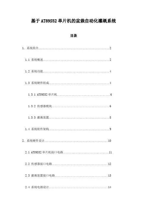
基于AT89S52单片机的盆栽自动化灌溉系统目录1. 系统简介 (2)1.1 系统概述 (2)1.2 系统功能 (4)1.3 系统硬件组成 (4)1.3.1 AT89S52单片机 (6)1.3.2 传感器模块 (6)1.3.3 灌溉装置 (8)1.4 系统软件架构 (9)2. 系统硬件设计 (10)2.1 AT89S52单片机接口电路 (11)2.2 传感器接口电路 (12)2.3 灌溉装置接口电路 (13)2.4 系统电源设计 (14)3. 系统软件设计 (15)3.1 系统工作流程 (17)3.1.1 初始化程序 (18)3.1.2 数据采集程序 (19)3.1.3 控制程序 (20)3.1.4 状态输出程序 (21)3.2 每部分程序设计说明 (22)3.2.1 初始化程序 (23)3.2.2 数据采集程序 (24)3.2.3 控制程序 (26)3.2.4 状态输出程序 (27)4. 系统调试与测试 (28)4.1 系统调试步骤 (29)4.2 测试方法及指标 (30)4.3 故障处理 (31)5. 未来展望 (33)1. 系统简介本“基于89S52单片机的盆栽自动化灌溉系统”旨在开发一种智能、高效的盆栽灌溉解决方案。
这套系统利用89S52作为核心控制器,结合传感器技术、电子测量及遥控技术,能够实现对盆栽土壤水分的自动化检测与精准灌溉。
该系统采用实时土壤湿度感应机制,可定时检测盆栽土壤的湿度情况,并通过单片机内部程序处理数据,判断是否需要启动灌溉。
当土壤湿度达到预设的下限值时,系统自动启动灌溉定时器,通过电机驱动滴灌装置为盆栽供水,确保植物获得适宜的水分支持。
此外,本系统还提供了用户界面,允许用户根据盆栽的具体需求设定灌溉策略,如灌溉时间、水量以及湿度阈值等。
系统设计还考虑了节能环保,支持在盆栽水分充足的情况下进入待机模式以减少不必要的能耗。
最终该系统实现了一种既节约水资源又省时省力的盆栽养护方式,尤其适合忙碌的现代人及植物爱好者使用。
精品文档值得下载威海职业学院毕业设计任务书专业电子工艺与管理年级2009班级姓名娄和昆学号20090208051威海职业学院教务处编印精品文档毕业设计指导须知一、毕业设计是高职教学过程中一个十分重要的环节。
是锻炼学生运用所学知识正确分析和解决实际问题的一个重要方面,也是高职培养应用型专门人才的要求。
二、导师应为具有讲师以上或相应职称的有关专业人员,且专业对口(指所指导专业应同所聘教师专业职称相一致)。
经系、教务处审查同意后,才能指导学生的毕业设计。
三、学生应以严肃认真,实事求是的态度完成设计。
要独立思考,自己动手,不得抄袭或找人代笔。
四、毕业设计选题要符合专业培养目标的要求。
论文(任务书)写作要做到论点明确、论据充分,论理透彻,语言准确恰当,书面整洁、字迹工整,图纸应清晰、工整,符合设计要求,符合国家有关标准和部颁标准。
字数、图纸数量符合有关要求。
并在规定的时间内完成。
五、答辩过程中学生要严认真,文明礼貌,谦虚谨慎,认真回答答辩主持人,委员等提出的问题。
六、填报有关表格时,应按项目要求逐项填实、填全、填清。
值得下载值得下载精品文档答辩情况记录答辩情况不正确未回答答辩题目正确基本正确经提示回答此表由主持答辩的同志填写。
答辩委员会(或小组)评语:成绩:主持答辩人签名:职称:月日值得下载值得下载精品文档自动控制浇花系统摘要现代生活中,随着人们生活水平的提高,人们对花卉、树木等绿色植物的喜爱和种植越来越多,然而以前对花木的浇灌、施肥等工作都需要靠人工来实现,由于现代生活节奏的加快,人们往往忙于工作而忘记定期、及时地为花卉补充水分及养料,或者由于放假回家而将花放在办公室等处没人管理导致花木枯死。
水是植物生存、生长的最基本需要,因此,设计一种能够在无人管理的情况下为花木自动浇水的系统,能够有效的防止花木在上述情况下的枯死。
单片机因体积小、质量轻、价格便宜等优点已经广泛地应用在我们日常的生产和生活当中。
它能通过编写的程序实现高智能、高效率、高可靠性地任务完整执行。
单片机自动浇花系统毕业设计毕业设计题目:基于单片机的自动浇花系统1.设计目的和意义为解决现代社会中常见的人们忙碌,缺乏时间照顾植物的问题,利用单片机技术设计一套自动浇花系统,能够实现在一定的时间间隔内根据种植植物的需求自动进行浇水和护理,达到养护植物的目的,减轻人们的负担,提高生活质量。
2.设计方案本系统采用单片机控制浇水,利用温湿度传感器感应土壤湿度情况及环境温湿度,从而确定自动浇花的适宜时机,控制水泵实现自动浇水。
同时采用光照传感器感应环境光照强度,从而确定室内亮度情况,控制LED灯实现自动补光。
此外,系统采用LCD显示屏展示环境温度、湿度、光照强度和浇水状态等信息,方便用户监控植物生长情况。
具体实现方案如下:1)硬件部分:- 单片机:采用51单片机;- 人机交互:采用液晶显示屏;- 传感器:温度传感器、湿度传感器、光照传感器;- 输出设备:水泵、LED灯。
2)软件部分:- 采用C语言编写,利用单片机的定时器和ADC功能实现温度、湿度、光照强度的采集;- 实现温度、湿度和光照强度的数据处理;- 根据采集的土壤湿度情况和植物的需求,确定自动浇水时机,控制水泵实现浇水;- 根据采集的光照强度情况,确定自动补光时机,控制LED灯进行补光;- 实现LCD显示屏显示环境信息和系统状态信息。
3.实现步骤- 电路设计和制作:包括单片机电路、传感器接口、输出设备接口等;- 编写单片机程序:包括温湿度传感器数据采集、光照传感器数据采集、数据处理、控制水泵浇水、控制LED灯补光、LCD显示等功能;- 软硬件测试:测试程序与硬件是否协调运行,是否能正常采集传感器数据并控制输出设备;- 调试和优化:根据测试结果对程序进行修改和优化。
4.预期效果本设计预期实现以下功能:- 根据土壤湿度情况和植物的需求自动浇水;- 根据光照强度情况自动补光;- 通过LCD显示屏实时显示环境温度、湿度、光照强度等信息;- 用户可以通过液晶显示屏进行操作、设置等。

毕业论文﹙设计﹚自动浇花系统的设计[摘要]本设计主要的内容是土壤湿度检测电路的设计与制作。
该电路的工作原理是由STC89C52单片机和ADC0832组成系统的核心部分,湿度传感器将采集到的数据直接传送到ADC0832的IN端作为输入的模拟信号。
选用湿度传感器和AD转换,电路内部包含有湿度采集、AD转换、单片机译码显示等功能。
单片机需要采集数据时,发出指令启动A/D转换器工作,ADC0832根据送来的地址信号选通IN1通道,然后对输入的模拟信号进行转换,转换结束时,EOC输出高电平,通知单片机可以读取转换结果,单片机通过调用中断程序,读取转换后的数据。
最后,单片机把采集到的湿度数据经过软件程序处理后送到LCD1602进行显示。
自动浇水系统设计为智能和手动两个部分:智能浇水部分是通过单片机程序设计浇水的上下限值与感应电路送入单片机的土壤湿度值相比较,当低于下限值时,单片机输出一个信号控制浇水,高于上限值时再由单片机输出一个信号控制停止浇水;手动部分是由通过关闭单片机电源,由外围电路供电进行浇灌、[关键词]STC89C52干湿度的采集与显示 LEDDesign of potted flowerss automatic watering system(Grade 08,Class 3,Major electronics and information engineering ,School of physics andAbstract the design of potted plant automatic watering system includes soil temperature and humidity acquisition and display, and the counter setting and display and alarm two parts water. Soil temperature and humidity acquisition and display part, and comprises a soil temperature and humidity acquisition and display, automatic watering system. Soil temperature and humidity acquisition and display in ADC0832is connected with two potentiometers as an induction circuit, the collected soil temperature and humidity value is send to the STC89C52 single chip, then by its transmission to the LCD screen display. Automatic watering system design for intelligent and manual two parts: intelligent watering section through the MCU programming watering the upper limit and the lower limit and the induction circuit into the microcontroller 's soil humidity value are compared, when less than the lower limit value, the MCU output a signal to control the watering, high in the upper limit value by the microcontroller output a signal control stop watering; manual part is composed of single-chip digital tube into the month and day from real time, through the software programmed timing watering time.Key words :STC89C52 temperature and humidity acquisition in the display counter LED引言1选题的目的和意义随着社会的进步,人们的生活质量越来越高。
基于单片机的自动节水灌溉系统摘要节水灌溉-农业节水不仅潜力很大而且利国利民。
对占消费水80%左右的农业用水的合理使用和发挥最大效益应该说具有非常重要的意义。
尤其对于处在干旱、半干旱地区的大半个中国,节水将是可持续发展需要解决的最重要问题。
单片机可编程控制节水灌溉系统,该系统可对不同土壤的湿度进行监控,并按照作物对土壤湿度的要求进行适时、适量灌水.本控制器以AT89C51单片机为核心,由传感器,信号处理电路、输出控制电路等构成。
以实现数据采集、控制信号输出,通过传感器自动检测土壤水分实现自动灌溉控制。
硬件方面,土壤含水量的测量采用HIH3610湿度传感器;A/D转换采用ADC0809芯片,74LS373芯片等。
单片机控制部分采用AT89C51单片机为核心,主要由土壤湿度传感器,信号处理电路,输出控制电路等组成,软件选用汇编语言编程。
单片机可将土壤湿度传感器检测到的土壤湿度模拟量转换成数字量,并传输给控制系统检测是否该灌溉。
该系统灵活性强,成本低,可靠性高,在实际应用中前景广阔。
关键词:单片机芯片采样 A/D转换河北大学2009届本科生毕业论文(设计)ABSTRACTStanza water irrigation-agriculture stanza water not only the potential but is very big and benefit people of country.To have to consume water 80% or so agriculture to use aqueous of reasonable usage and develop the biggest efficiency should say having count for much meaning.Particularly for be placed in the greater half inside country of drought, the half dry region, stanza water will be keep on the development needs to be solved the most important problem.The single slice of machine programmable control stanza water irrigation system, that system can carry on supervision to the degree of humidity of different soil, and Be according to the request of farm crop to soil degree of humidity carry on in good time and just the right amount infusing water.This controller takes the AT89 C51 single slice of machine as core, from spread a feeling machine, the signal handles electric circuit and output control electric circuit etc. composing.Collect by carrying out a data, control signal output, pass to spread a feeling machine an auto examination the soil humidity carry out an automatic irrigation control.Hardware, the soil contains the diagraph adoption HIH3610 degree of humidities of amount of water to spread a feeling machine;A|D convert the adoption ADC0809 chips, 74 LS373 chip etc..Single slice of machine control part adoption the AT89 C51 single slice of machine is mainly spread a feeling machine by soil degree of humidity, the signal handles electric circuit and outputs control electric circuit etc. to constitute, the software choice edits collected materials a language plait distance.The single slice of machine can spread soil degree of humidity, the feeling machine examines of the soil degree of humidity imitates quantity to convert into a number quantity, and deliver to control system examination whether should irrigate.The system's vivid is strong, the cost is low, High reliability, at physically applied in foreground vast.Keyword: single chip Chip Sample A| D convert目录一前言 (1)1.1本设计的任务和主要内容 (1)二本系统主要硬件电路设计及介绍 (2)2.1本系统主要硬件介绍及总体说明: (2)2.2简介AT89C51内部总体结构及其基本特性如下: (2)2.3湿度传感器介绍 (3)2.4A/D模块介绍 (4)2.5电动机介绍 (6)2.6电磁阀,喷头 (7)三本系统主要硬件电路设计 (9)3.1系统的工作原理 (9)3.2单片机主系统电路 (9)3.3时钟电路 (10)3.4数据存储器的扩展电路 (11)3.5数据采集处理电路 (11)3.6LED显示系统电路 (12)四系统的软件设计 (15)4.1系统主程序设计 (15)4.2采样子程序设计 (17)4.3数据处理 (17)4.3.1采集数据转换 (17)4.3.2BCD转换 (19)4.4LED动态显示程序 (19)结论 (21)谢辞 (22)参考文献 (23)一前言水是生命之源,没有了水,地球上的生物都将消失。
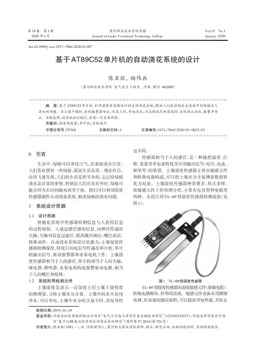
一个家用自动浇花系统的设计摘要本系统以at89c52单片机为主控制器,利用温度传感器ds18b20、光敏电阻、湿度传感电路来采集信息,对其进行分析处理驱动电磁阀动作,实现定时和按需浇灌功能。
实现了花卉在无人看护的情况下,及时补充水分所需。
关键词 at89c52 ds18b20 光敏电阻传感器现代生活中,随着人们生活水平的提高,人们对花卉、树木等绿色植物的喜爱和种植越来越多,往往在家中或办公室点缀以名贵品种的花木,以提高生活的品味。
然而以前对花木的浇灌、施肥等工作都需要靠人工来实现,由于现代生活节奏的加快,人们往往忙于工作而忘记定期、及时地为花卉补充水分,或者由于放假回家而将花放在办公室没有人管理导致花木枯死。
基于以上原因设计了一个家用自动浇花系统。
一、系统功能介绍定量浇花。
实现每天在规定的时间自动打开电磁阀浇花,根据不同的花卉所需水量不通,用一个按钮来设置浇花时间的长短(数码管显示)即电磁阀打开的时间,其余时间电磁阀闭合,水流不经过。
通过适度传感器检测湿度,当检测到的湿度低于设定的最低湿度值,就开始浇花,直到湿度达到规定范围内;当检测到湿度高于设定的最高湿度值时,即使其他情况都符合要求,也均不给水。
通过光敏电阻检测当前的光照强度,当有光照时,检测温度传感器是否达到上限值,若达到则检测温度,若未达到,则进行循环检测。
通过温度传感器检测温度,当温度达到自己设定限制时放水浇花,若温度未达到自己设定的限制则不给水。
二、硬件系统方案设计根据实际需要,设计了一套温度、湿度和光照检测与控制系统,保证花卉在生长的各个时期有适宜的生长环境。
硬件电路以at89c52单片机为核心,系统输入由采集土壤湿度传感器、光照传感器和温度传感器、信号处理电路、输出控制电路组成。
软件采用c语言编程,采用模块式结构设计。
整个系统的硬件结构如图1-1所示。
图1-1硬件结构图1、土壤湿度传感器土壤湿度是最重要和最常用的土壤信息,它是科学地控制调节土壤水分状况,进行节水灌溉,实现科学用水的基础。
目录1 课程设计背景、容和意义 (1)1.1课程设计背景 (1)1.2 课程设计容和意义 (1)2总体电路设计和元器件的选型 (2)2.1总体电路设计 (2)2.2 元器件的选型 (3)3 模块电路设计 (13)3.1 电源设计 (13)3.2 温度采集模块 (14)3.3 湿度采集模块 (14)3.4显示模块 (15)3.5 控制模块 (16)3.6 A/D转换模块 (17)3.7 S51单片机控制模块 (18)3.8 通信模块 (19)4 PROTEL DXP电路图设计 (21)5 制作PCB板 (22)6系统软件设计 (23)6.1 LCD12864程序编写流程图 (23)6.2 PCF8951程序编写流程图 (24)6.3 DS18B20程序编写流程图 (25)6.4 GSM模块程序编写流程图 (27)7 系统调试 (27)7.1 硬件测试 (27)7.2 软件测试 (28)8 总结 (29)参考文献30致词31独撰声明32翻译资料 (33)附录 (44)1 课程设计背景、容和意义1.1课程设计背景GSM(Global System for Mobile communication)系统是目前基于时分多址技术的移动通信体制中,比较成熟完善,且应用最广泛的一种系统。
目前已建成的覆盖全国的GSM数字蜂窝移动通信网,是我国公众移动通信网的主要方式。
基于GSM的短信信息服务,是一种在移动网络上传送简短信息的无线应用,是一种信息在移动网络上存储和转寄的过程。
由于公众GSM网络在全球围实现了联网和漫游,所以具有实时传输数据功能的短信应用将得到迅速普与。
利用GSM网络作为无线智能监控模块的信息传输平台是一种很有效的方法。
其原理简单,安全性高,又不需要组建专用网络和维护网络,加上GSM网络覆盖面广,可实现全球无缝覆盖,与传统的监控系统相比有着独特的优势。
运用GSM网络短消息进行通信的通用智能监控模块,可广泛地应用在智能家居防盗、远程监控、无人值守设备的维护与现代自动化生产线的监控等领域。
基于AT89S52的家庭智能浇花器设计方案随着人们生活水平的提高,花卉逐渐收到人们的青睐,陶冶情操,净化空气。
利用设计了一款家庭智能浇花器实现自动浇花,节约人力,便利人们出差的时候,不至于影响花卉的生长,假如在家也可以关断浇花器,手动浇花。
浇花器设置为两种方式,一种是定时定量浇花,一种是按照湿度浇花。
采纳哪种方式是通过按键控制或者遥控的,在采纳定时定量浇花时,数码管显示时光和流水时光,在选用按照湿度浇花时,数码管显示是目前的湿度。
1 总体设计利用AT89S52单片机设计了自动浇花器,针对不同的花卉,此智能浇花器设置为两种方式:一是定时定量浇花,二是利用湿度检测花卉(也可以用于蔬菜等)的湿度,采集的湿度传送到单片机芯片,单片机按照湿度控制是否浇水,假如需要浇水,单片机的一个引脚p2.0置高电平,使线圈通电,放开触点闭合,打开电磁阀,实现定时定量的自动浇水,设定时光到,电磁阀自动闭合,并且水流时光可调,上面安装了数码管,并有一个按钮按照不同花卉所需水量不同,设置浇花时光长短,在数码管上可以显示浇水时光的长短;假如检测湿度足够,p2.0仍保持为低电平,不打开电磁阀。
采纳哪种方式是通过按键控制或者红外遥控的,在采纳定时定量浇花时,数码管显示时光和流水时光,在选用按照湿度浇花时,数码管显示是目前的湿度。
该技术所采纳的技术计划是:利用单片机实现自动控制,首先检测采纳何种方式浇花,假如定时定量浇花,就在规定的时光开头浇花,根据设置浇花时光的长短举行浇花;假如是按照湿度控制是否浇水就设置单片机1个引脚为低电平,湿度传感器检测湿度,传送给单片机芯片,当检测到湿度不够时,单片机这个引脚就变为高电平,把继电器吸合,常开触点闭合,使得电磁阀线圈得电,此时电磁阀门有闭合变成断开,水流经过,给花卉浇水。
其结构1所示。
2 硬件设计硬件由单片机、湿度传感器、继电器、电磁阀、数码管、1302芯片、按键、红外遥控接收等组成。
注重,电磁阀假如安放离单片机太近,将会造成无法正常工作,解决办法是:1)电磁阀远离单片机;2)加入。
基于单片机的智能浇花系统的设计与实现摘要随着科学的不断发展和人们生活水平的不断进步,人们对于生活质量的要求也越来越高,花草养殖成为了家庭生活中的一部分,人们养殖花草的目的大多是为了陶冶情操和提高室内外的空气质量等等,但由于工作繁忙等原因,不能按时给花草浇水成为了花卉死亡的主要原因。
本文利用AT89C51单片机设计了一种自动浇花控制系统,此系统可为人们解决因工作等原因无法按时为花卉浇水的问题,以便于花卉茁壮成长。
本设计采用汇编语言进行编程,在LED液晶屏上实现小时,分,秒的显示;并利用单片机来实现计时,定时功能,同时通过4个按键开关来实现参数设置和调节功能、浇花间隔时间的设定、浇水持续时间的设定、单片机对电磁阀的自动控制。
根据用户设定的时间顺利的完成浇花任务。
关键词:单片机,控制,显示,电磁阀大连东软信息学院毕业设计(论文) Abstract Design and implementation of the IntelligentControl System for Watering the Flowersbased on single chip microcomputerAbstractWith the continuous development of science and the people life level of progress , people for the requirements of the life quality is more and more rigorous , plants breeding become part of the family life. The purposes of people breeding plants are for the edify sentiment and improve the indoor and outdoor air quality and so on. Because of the busy jobs and other factors, the inability to water the flowers and plants become the main cause of death. In this paper, AT89C51 single-chip microcomputer designed a kind of automatic watering the flowers control system. The system can work for people who can not water the flowers on time, so that the flowers can grow strength and healthy.This design uses the assembly languages programming, realizing hours, points, second display on LED; And using single chip computer to realize the timing, timing function, and at the same time through four button switches to achieve parameter setting and adjustment function, the water the flowers of the interval time set, the duration of water with the chip set, solenoid valve to be automatic control. According to users setting time done smoothly the task of watering the flowers.Key words: MCU, control, display, solenoid valve目录摘要 (I)ABSTRACT (II)第1章绪论 (1)1.1课题研究背景与意义 (1)1.2课题研究内容与方法 (1)1.3课题研究现状 (2)第2章关键技术介绍 (4)2.1单片机介绍 (4)2.2继电器的工作原理和特性 (4)第3章系统需求分析 (5)3.1系统设计目标 (5)3.2系统功能需求 (5)3.2.1 单片机最小系统 (5)3.2.2 显示模块 (5)3.2.3 电机驱动模块 (5)3.2.4 按键模块 (6)3.2.5 AD转换模块 (6)3.3系统非功能需求 (6)3.4系统开发环境 (6)3.5系统可行性分析 (6)第4章系统设计 (7)4.1系统设计指导原则 (7)4.2体系结构设计 (7)4.3硬件设计 (7)4.3.1 STC89C52单片机介绍 (7)4.3.2 单片机最小系统 (9)4.3.3 复位电路 (9)4.3.4 时钟电路 (10)4.3.5 AD转换模块 (10)4.3.6 显示模块 (12)4.3.7 水泵驱动模块 (13)4.4软件设计 (14)4.4.1 主程序流程及相关说明 (14)4.4.2输入模块 (15)4.4.3 AD转换程序 (16)第5章系统实现 (18)5.1环境配置 (18)5.2功能模块实现 (19)5.2.1 主函数实现 (19)5.2.2 LCD1602数据读取函数实现 (20)5.2.3 延迟函数实现 (22)第6章系统测试 (24)6.1测试概述 (24)6.2测试结果分析 (24)第7章结论 (25)参考文献 (26)致谢 (27)第1章绪论1.1 课题研究背景与意义随着社会生活的进步,人们的生活质量越来越高。
基于单片机的自动浇花系统的设计自动浇花系统是一种能够根据植物的需水情况自动进行浇水的智能设备。
它利用单片机控制花盆的浇水行为,通过传感器感知土壤湿度,从而实现自动控制系统。
本文将详细介绍基于单片机的自动浇花系统的设计。
一、引言现代社会,人们生活节奏加快,忙碌的工作使得人们无法经常照顾家中的花卉。
因此,研发一种能够自动浇花的系统具有重要意义。
本文通过基于单片机的自动浇花系统的设计,实现了智能浇花的功能。
二、系统设计1. 硬件设计本系统主要由单片机、土壤湿度传感器、水泵及其他辅助元件组成。
单片机负责接收传感器的输入信号,并根据预设的阈值控制水泵的开关。
土壤湿度传感器采集土壤湿度信息,当土壤湿度低于预设阈值时,传感器会向单片机发送信号。
水泵负责将水从储水箱中抽取,并通过管道灌溉到花盆中。
2. 软件设计单片机的程序主要由两部分组成:传感器数据采集和控制逻辑。
传感器数据采集部分负责实时获取土壤湿度传感器的数据,并将其转换成可供控制逻辑使用的数字信号。
控制逻辑部分负责根据传感器数据判断是否需要浇水,并控制水泵的开关。
三、系统工作流程1. 初始化系统启动时,单片机会对各个元件进行初始化设置,包括传感器的校准和水泵的状态。
2. 数据采集单片机不断地从土壤湿度传感器中读取数据,并将其转换成数字信号。
传感器数据的采集频率可以根据实际情况进行调整。
3. 数据处理单片机根据传感器数据判断土壤湿度是否低于预设阈值。
如果低于阈值,则需要浇水;如果高于阈值,则不需要浇水。
4. 控制水泵根据数据处理的结果,单片机会控制水泵的开关。
当需要浇水时,单片机会发送信号给水泵,使其开始工作;当不需要浇水时,单片机会发送信号给水泵,使其停止工作。
5. 循环执行系统会不断地循环执行上述步骤,以实现实时监测和自动浇花的功能。
四、系统优势基于单片机的自动浇花系统具有以下优势:1. 省时省力:系统能够根据植物的需水情况自动进行浇水,省去了人工浇水的麻烦。
智能浇花设计 STC89C52概述智能浇花系统是一种利用传感器和控制器实现自动浇花的系统。
本文档介绍了基于STC89C52单片机设计的智能浇花系统的原理和实现方法。
该系统能够根据土壤湿度和环境温度等参数,自动判断植物是否需要浇水,并进行相应的控制操作。
通过设计智能浇花系统,可以提高浇花效率,减少人工浇花的工作量,同时保证植物的健康生长。
系统组成智能浇花系统主要由以下几个部分组成:1.STC89C52单片机2.土壤湿度传感器3.温度传感器4.水泵控制模块5.显示模块系统工作原理智能浇花系统的工作原理如下:1.土壤湿度传感器感测土壤湿度:土壤湿度传感器通过测量土壤中的湿度来判断植物是否需要浇水。
当土壤湿度低于设定阈值时,传感器会向单片机发送信号。
2.温度传感器感测环境温度:温度传感器用于感测环境的温度,以便在浇水前判断是否需要将水加热或者保持在适宜的温度范围。
3.单片机控制器处理传感器数据:STC89C52单片机接收传感器发来的信号,并根据设定的阈值判断植物是否需要浇水。
同时,单片机还会根据环境温度来控制水泵的工作,以保持适宜的浇水温度。
4.水泵控制模块控制水泵:当单片机判断植物需要浇水时,水泵控制模块会接收到单片机的指令,然后控制水泵的工作。
水泵会将水从水箱中抽取出来,并通过喷头均匀地浇洒到植物的根部。
5.显示模块显示系统状态:显示模块可以用于显示系统的状态,包括当前的土壤湿度、环境温度以及是否正在进行浇水等信息。
系统功能智能浇花系统主要具有以下几个功能:1.自动浇水:根据土壤湿度和环境温度的检测结果,系统可以自动判断植物是否需要浇水,并进行相应的控制操作。
2.水温控制:系统可以根据环境温度的检测结果,判断是否需要加热水泵中的水。
如果环境温度较低,系统会自动加热水泵中的水,以保持适宜的浇水温度。
3.状态显示:系统能够通过显示模块实时显示当前的土壤湿度、环境温度以及是否正在进行浇水等信息。
4.高效节水:通过智能浇水系统的控制,可以准确判断植物的需要,避免过多或过少的浇水,确保植物的健康生长,同时也能够节约水资源。
毕业设计(论文)-基于A T89C52单片机的自动浇花系统. 课题:自动浇花系统摘要本系统以方便人们花卉的浇水,实现智能浇花,让人们从繁琐的浇花工作中解放出来,自动浇花系统的设计和应用应运而生。
本系统采用AT89C52单片机,配以相应的外围电路完成土壤含水量的检测和自动浇花的控制过程。
由土壤湿度传感器采集土壤信息,再经过信息处理模块处理后由ADC0832 A/D转换芯片转换成数字信号,AT89C52单片机作为控制中心。
配以DS1302 时钟芯片、LCD1602液晶显示模块等组成数据处理控制模块,实现智能浇花,显示时钟功能。
通过一系列的设计实现,简单的电路及低价的成本实现自动浇花系统是可行的,进一步可以推广到蔬菜大棚,园林,草地等的自动浇灌管理。
对于实现科技服务生活具有重要意义。
关键词:浇花,AT89C52单片机,ADC0832,DS1302,土壤湿度传感器,时钟AbstractThis system for people convenience and intelligent water flowers and plants, let people work from trival watering the flowers liberate,automatic watering the flowers system design and application arises at the historic moment. The system uses the AT89C52 single chip computer,match with corresponding buffer circuit for the soil moisture content detection and finish the control process of automatic watering the flowers. From the soil humidity sensors to collect soil information, and then after the information processing module processing by ADC0832 after A/D conversion chip converted into digital signals, AT89C52 single chip computer as the control center. Match with DS1302 clock chip, LCD1602 LCD module data processing control module, realize intelligent water flowers,display clock function. Through a series of design and implementation, simple circuit and low cost to implement the automatic watering the flowers system is feasible, further can be extended to vegetable shed, garden, the automatic watering system. For technology service life is Important significance.Keywords: water flowers, AT89C52, ADC0832, DS1302, soil moisture sensor, clock目录1 前言......................................................... 11.1论文设计的意义.......................................................................................................... 11.2湿度测量方法及湿度测量方案.................................................................................. 11.3论文的主要内容.......................................................................................................... 32 自动浇花系统的基本理论....................................... 42.1土壤湿度传感器.......................................................................................................... 42.2土壤湿度信号转换...................................................................................................... 42.3土壤湿度信号调理...................................................................................................... 53 系统硬件设计................................................. 63.1系统技术指标.............................................................................................................. 63.2系统框图...................................................................................................................... 63.3芯片选择...................................................................................................................... 63.4系统传感电路设计...................................................................................................... 83.4.1 土壤湿度传感器的设计................................................................................... 83.4.2 土壤湿度信号调理电路................................................................................. 93.4.3 A/D转换处理模块..................................................................................... 123.5系统显示电路设计.................................................................................................. 133.5.1 显示模块的选择........................................................................................... 133.5.2 显示电路....................................................................................................... 143.6系统控制电路设计.................................................................................................. 153.6.1 按键电路....................................................................................................... 153.6.2 电磁阀控制电路........................................................................................... 163.7电路原理图.............................................................................................................. 164 系统软件设计............................................... 184.1总设计框图.............................................................................................................. 184.2传感转换流程图...................................................................................................... 184.3控制模块流程图...................................................................................................... 195 系统调试................................................... 215.1 系统硬件测试......................................................................................................... 215.2 系统的软件测试..................................................................................................... 215.3系统整体调试.......................................................................................................... 215.4系统测量与误差分析.............................................................................................. 226 总结...................................................... 23附录......................................................... 24附录A 原理图................................................ 24附录B PCB图................................................ 25附录C 程序 ................................................ 26参考文献..................................................... 41致谢......................................................... 431 前言1.1论文设计的意义在电子技术日新月异的今天,生活中到处都可以看到嵌入式单片机的应用实例。
摘要本次设计的盆花自动养护系统经过对土壤温度,湿度与光照的检测,从而控制电磁阀,步进电机,窗户的开关来达到花卉生长所需要的条件。
土壤温湿度的检测与控制部分包括了土壤温湿度的检测和自动浇水系统。
土壤温湿度的检测和显示以温湿度传感器为感应部件,将检测到的土壤温湿度值送入AT89C52单片机,再由其控制电磁阀工作。
自动浇水系统智能浇水部分是通过单片机程序设定浇水的上下限值与送入单片机的土壤湿度值相比较,当低于下限值时,单片机输出一个信号控制电磁阀打开,开始浇水,高于上限值时再由单片机输出一个信号控制电磁阀关闭,停止浇水;当光照较强时,由单片机控制电机将窗帘拉下,遮挡阳光。
温度较高时,打开窗户进行散热。
本文为阳台自动养花进行了初步探索和实验,取得了一些对开发设计新产品有益的数据和经验。
关键词:AT89C51单片机温湿度传感器光照传感器 C52程序数字电路ABSTRACTThe design of automatic maintenance system is based on pot soil temperature, humidity and light detection. It can control the electromagnetic valve, step motor and the window switch to achieve flowers who require conditions.Soil temperature and humidity measurement and control of parts of the temperature and humidity includes test and automatic water system. Soil temperature and humidity in the detection take the temperature and humidity sensor for inductive components. Detect soil temperature and humidity value to single chip microcomputer AT89C52, then it control the electromagnetic valve working.Automatic watering water system intelligence part compares the limit that micro controller program set up for the water. When it lower the limit, SCM outputs a open signal electromagnetic valve control ,then starting watering. When it is higher than the upper limit value, the single chip microcomputer output a signal control electromagnetic valve, closeing and stoping water; When light is stronger, the single chip microcomputer control motors will pull the curtain and shade from the sun. If higher temperature, open the window to cool. This article for the balcony to be automatic flowers were discussed , making some useful data and experience to develop the new products .Key words: AT89C52 , micro controller temperature and humidity sensor, clock chip DS1302, C51 program, digital circuit目录第一章绪论 (6)1.1 选题的目的与意义 (6)1.2自动浇花器的诞生背景及国内外发展现状 (6)1.3本论文的主要研究内容 (8)第二章系统的总体设计 (9)2.1应用场合与工作环境 (9)2.2 系统预期功能与技术指标 (10)2.3系统设计总体方案 (10)2.4系统的工作原理 (11)第三章系统的硬件设计 (12)3.1单片机控制系统设计 (12)3.1.1单片机的选择 (12)3.1.2 AT89S52简介 (12)3.1.3存储器的配置 (16)3.1.4时钟电路和复位电路的设计 (16)3.2 数据采集电路的设计 (17)3.3 太阳能电池板充电电路.......................................。
毕业设计(论文)-基于A T89C52单片机的自动浇花系统. 课题:自动浇花系统摘要本系统以方便人们花卉的浇水,实现智能浇花,让人们从繁琐的浇花工作中解放出来,自动浇花系统的设计和应用应运而生。
本系统采用AT89C52单片机,配以相应的外围电路完成土壤含水量的检测和自动浇花的控制过程。
由土壤湿度传感器采集土壤信息,再经过信息处理模块处理后由ADC0832 A/D转换芯片转换成数字信号,AT89C52单片机作为控制中心。
配以DS1302 时钟芯片、LCD1602液晶显示模块等组成数据处理控制模块,实现智能浇花,显示时钟功能。
通过一系列的设计实现,简单的电路及低价的成本实现自动浇花系统是可行的,进一步可以推广到蔬菜大棚,园林,草地等的自动浇灌管理。
对于实现科技服务生活具有重要意义。
关键词:浇花,AT89C52单片机,ADC0832,DS1302,土壤湿度传感器,时钟AbstractThis system for people convenience and intelligent water flowers and plants, let people work from trival watering the flowers liberate,automatic watering the flowers system design and application arises at the historic moment. The system uses the AT89C52 single chip computer,match with corresponding buffer circuit for the soil moisture content detection and finish the control process of automatic watering the flowers. From the soil humidity sensors to collect soil information, and then after the information processing module processing by ADC0832 after A/D conversion chip converted into digital signals, AT89C52 single chip computer as the control center. Match with DS1302 clock chip, LCD1602 LCD module data processing control module, realize intelligent water flowers,display clock function. Through a series of design and implementation, simple circuit and low cost to implement the automatic watering the flowers system is feasible, further can be extended to vegetable shed, garden, the automatic watering system. For technology service life is Important significance.Keywords: water flowers, AT89C52, ADC0832, DS1302, soil moisture sensor, clock目录1 前言......................................................... 11.1论文设计的意义.......................................................................................................... 11.2湿度测量方法及湿度测量方案.................................................................................. 11.3论文的主要内容.......................................................................................................... 32 自动浇花系统的基本理论....................................... 42.1土壤湿度传感器.......................................................................................................... 42.2土壤湿度信号转换...................................................................................................... 42.3土壤湿度信号调理...................................................................................................... 53 系统硬件设计................................................. 63.1系统技术指标.............................................................................................................. 63.2系统框图...................................................................................................................... 63.3芯片选择...................................................................................................................... 63.4系统传感电路设计...................................................................................................... 83.4.1 土壤湿度传感器的设计................................................................................... 83.4.2 土壤湿度信号调理电路................................................................................. 93.4.3 A/D转换处理模块..................................................................................... 123.5系统显示电路设计.................................................................................................. 133.5.1 显示模块的选择........................................................................................... 133.5.2 显示电路....................................................................................................... 143.6系统控制电路设计.................................................................................................. 153.6.1 按键电路....................................................................................................... 153.6.2 电磁阀控制电路........................................................................................... 163.7电路原理图.............................................................................................................. 164 系统软件设计............................................... 184.1总设计框图.............................................................................................................. 184.2传感转换流程图...................................................................................................... 184.3控制模块流程图...................................................................................................... 195 系统调试................................................... 215.1 系统硬件测试......................................................................................................... 215.2 系统的软件测试..................................................................................................... 215.3系统整体调试.......................................................................................................... 215.4系统测量与误差分析.............................................................................................. 226 总结...................................................... 23附录......................................................... 24附录A 原理图................................................ 24附录B PCB图................................................ 25附录C 程序 ................................................ 26参考文献..................................................... 41致谢......................................................... 431 前言1.1论文设计的意义在电子技术日新月异的今天,生活中到处都可以看到嵌入式单片机的应用实例。