最新parker比例阀
- 格式:doc
- 大小:1.69 MB
- 文档页数:30
比例阀维护和修理中需要注意哪些事项比例阀维护和修理保养Parker比例阀维护和修理中需要注意哪些事项电液伺服阀对液压系统有很高的要求,介质的颗粒清洁度要求不低于NAS6级。
伺服阀工作性能的稳定性很大程度上倚靠于液压系统介质品质的高处与低处。
除在液压泵站泵的出口安装出名义过滤精度为3bLm的过滤器外,在伺服阀的进口前还装有一个3pm的二级保护过滤器。
穆格伺服维护和修理中需要注意下列问题:1、伺服阀在发生故障前,往往可依据很多途径判定出它的工作状态,为此,预见性的更换较之被动更换,更能保证整个系统的工作稳定性。
2、在环境湿度较高的地方使用该阀时,应在油箱上安装可除湿的呼吸器,以保证介质的含水量不超过0.006%。
3、定期取样化验液压介质的颗粒污染度,并依据化验结果,订立出一个较合理的油品及滤芯更换周期,以保证介质的颗粒污染度不低于NAS6级。
4、更换下来的伺服阀,一般情况下经过修理便可再次使用,送专业厂家检修为宜,以确保伺服阀的性能牢靠。
电液比例阀进展历程特别悠久,它是一种输出量与输入信号成比例的液压阀,了解比例阀维护和修理及工作原理特别紧要。
它广泛应用于对液压参数进行连续掌控或程序掌控,电液比例阀工作原理和结构形式、工作特点,对比例阀负载感应和压力补偿原理进行了剖析讨论。
对电液比例阀不同应用,特别是工程机械先导把持和遥控方面应用进行了论述电液比例阀对简化工程机械操作、提率和作业精度以及实现智能化作业都有着极其紧要意义,其性能进一步提高和应用范畴日益拓宽必将使工程机械产品技巧水平到较大程度提高。
某推土机推土铲手动与电液比例先导把持实例。
当二位三通电磁阀不通电时,先导压力与手动减压式先导阀相通,梭阀选择来自手动先导阀压力对液动换向阀进行把持;当二位三通电磁阀通电时,先导把持压力油通向三通比例减压式先导阀,梭阀对液动换向阀进行把持。
电液比例阀是阀内比例电磁铁输入电压信号产生相应动作,使工作阀阀芯产生位移,阀口尺寸发生更改并以此完成与输入电压成比例压力、流量输出元件。
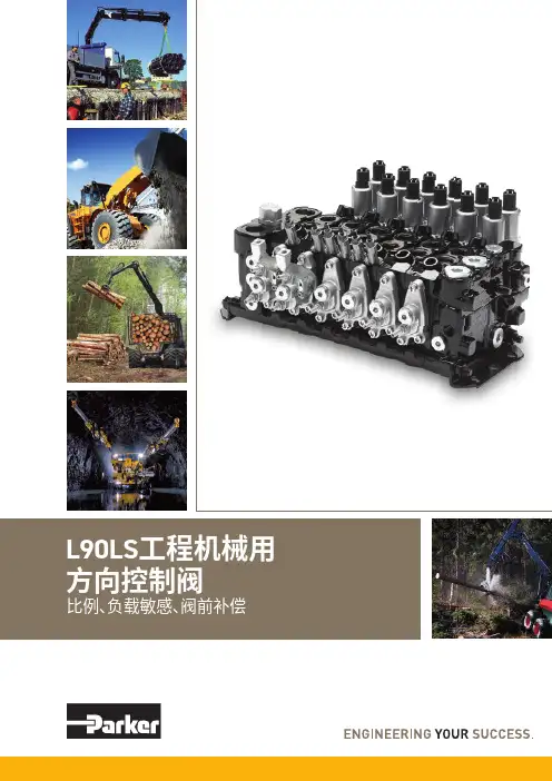
样本信息未使用本文所述之产品及相关项目选择不当或使用不当可能会造成人员死亡、警告样本布局除一般信息和基本技术数据外,该样本还对L90LS 可配置的选配功能做了描述。
我们可据此对L90LS 进行定制配置,以便以更佳的方式控制您的机器。
除一般信息和基本技术数据外,该样本还对阀门功能片中可配置的选配功能做了描述。
阀门的每个功能区域都有一个副标题,标题后面附有简短的描述。
如果某个功能区有多个不同的位置,则会在副标题的方括号内标注项目编号,例如[P16]溢流阀。
再接下来是一系列带有代号的选项,例如PA1、PS 、Y 以及每个代号的简短描述。
或者是一个或多个压力、流量或电压选项。
第8页的一般液压原理图中展示了L90LS 阀的基本功能区、以及代表这些功能区的条目编号。
有关L90LS 所有选项的信息,请参见样本MSG17-8504。
文档和订购L90LS 可在派克的在线产品配置器中根据客户的需求定制,定制规格通常在派克销售公司与客户协商后确定。
每个阀门配置都有唯一的ID 号、详细的代号报告、3D 模型、2D 图纸、备件清单、液压原理图、材料清单和装配说明。
除了前面提到的文档外,还登录XXXXX 观看每个选件的装配说明视频。
阀部件订购可使用物料清单通过派克销售公司进行。
尽早咨询,以节约时间和成本我们的工程师经验丰富,他们对不同类型的液压系统及其工作原理都有深入的了解。
他们可以帮助您选择符合要求的阀门。
我们建议在项目规划阶段尽早咨询派克。
派克保留修改产品的权利,恕不另行通知。
本样本中使用了典型的曲线和图表。
即使样本不断修订和更新,也不可避免存在出错的可能。
请联系派克汉尼汾,了解更多有关产品的详细信息。
概述 (4)技术数据 (5)压力 (5)内部先导压力 (5)通流流量 (5)重量 (5)过滤 (5)液压油 (5)温度 (5)[P03] 泵调节器设置 (6)油口 (6)[P04] 接口螺纹 (6)进口片 (6)工作片 (6)出口片 (6)液压原理图 (7)进口片 (8)[P15-P29] 进口片 (8)[P15] 进口片 (8)用于[P15] CFC、LS1进口片 (9)[P16] 溢流阀 (9)[P17] 压力设定 (9)用于[P15] LS2进口片 (9)[P16] 泄压阀 (9)[P17] 压力设定 (9)[P20] 负载信号系统 (10)[P25] 回油口T1 (10)[P26] 进油口P1 (10)出口片 (11)[P30 - P44] 出口片 (11)[P30] 出口片 (11)用于出口片[P30] US (12)[P31] LS油口 (12)[P32] 进油口P2 (12)[P33] 背压阀/回油口T2 (12)[P34] 回油口T3 (12)[P37] 内部先导压力供油 (12)[P39] 先导过滤器 (12)[P40] 回油口,用于先导回路..............................................12工作片.. (13)[P45-P89] 工作片 (13)[P47] 工作片的基本变型 (13)[P50] 阀芯执行器 (14)比例远程控制阀芯执行器,带封闭阀芯端 (14)比例远程控制阀芯执行器,带封闭阀芯端 (15)比例远程控制阀芯执行器,带封闭阀芯端 (16)手动控制阀芯执行器,带封闭阀芯端 (17)[P51] 手柄支架 (17)[P55A,B] 先导节流器 (18)[P56] 插头类型 (18)[P60] 阀芯功能 (19)[P64A, B] 力反馈 (20)[P66]压力补偿器/负载保持单向阀 (20)[P69] 阀芯名称 (21)[P71A,B] 工作油口公称流量 (21)[P72] 流量设定 (21)[P72A] 所需的设定流量 (21)[P72B] 所需的设定流量 (21)[P75] 进给减压阀 (21)[P75A] A油口的进给减压设定 (21)[P75B] B油口的进给减压设定 (21)[P76A,B] 油口溢流阀和/或防气穴阀 (22)信息 (23)[P50] EC2手动越权 (23)尺寸图 (24)备件 (25)L90LS具有四个工作段。
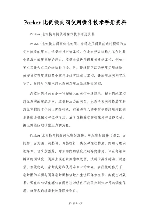
Parker比例换向阀使用操作技术手册资料Parker比例换向阀使用操作技术手册资料PARKER比例换向阀简称比例阀。
普通液压阀只能通过预调的方式对液流的压力、流量进行定值掌控。
但是当设备机构在工作过程中要求对液压系统的压力、流量参数进行调整或连续掌控,例如:要求工作台在工作进给时按慢、快、慢连续变动的速度实现进给,或按肯定精度模拟某个掌控曲线实现旅力掌控。
普通液压阀则实现不了。
这时可以用电液比例阀对液压系统进行掌控。
派克比例换向阀是一种按输入的电信号连续地、按比例地掌控液压系统的液流方向、流量和压力的阀类。
比例换向阀转换装置和液压掌控阀本体两大部分构成。
前者将输入的电信号连续地按比例地转换为机械力和位移输出,后者在接受这种机械力和位移之后、按比例连续地输出压力和流量.Parker比例换向阀有两组密封组件。
每组密封组件(图2)由阀瓣、密封圈、调整块、调整螺钉、夹板和螺栓构成。
阀瓣为碳钢板焊件,设有加强筋,即加添阀瓣强度又起导向作用,保证每组阀瓣间的同轴度。
阀瓣上镶嵌聚氨脂橡胶圈,该料子具有耐油、耐磨损、性能稳定、密封良好和使用寿命长的特点。
在凸轮的作用下,密封圈的球面与阀体密封面相接触产生挤压弹性变形,实现密封效果。
调整块和调整螺钉在两组密封组件不能同步到位时可起调整作用,确保各通道密封性能同步到位。
1夹板 2螺栓 3调整块 4阀瓣 5密封圈 6调整螺钉(3)阀杆与阀体隔板和上阀盖间的轴向密封采用O形圈。
(4)阀体隔板及上阀盖轴孔部位镶有铜套,可减小与O形圈间的摩擦力矩,密封组件开启与关闭敏捷,操作力矩小。
(5)上阀盖设有指示牌及限位螺钉,阀杆上安装指针,明确指示各通道的接通情形,易于操作。
派克Parker比例阀D1FB系列内置OBE放大器版本:这款内置了放大器位于一个坚固的金属外壳中,可以在特别恶劣的环境条件下使用。
标称值在出厂时已经设定。
串行RS232接口的电缆连接可作为附件供应。
派克D1FB系列外置放大器版本:这些参数可以与数字功率放大器PWD00A400结合起来进行保管、更改和复制。
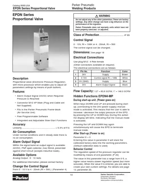
!DescriptionProportional valve (Electronic Pressure Regulator)with micro processor which enables you to adjust all parameters settings by means of push buttons.Features•Alarm Output Signal 24VDC when Required Pressure is Reached•Connector M12 4P Male (Plug and Cable are Not Supplied)•Fits in the Parker Pneumatic Frame-block (Air Service Unit)•Free Programmable Software•Integrated and Adjustable Slow-Start FunctionsAccuracyLinearity...................................................< 0.3% of F .SAir ConsumptionUnder normal conditions and in steady state there is no air consumption.Alarm Output SignalWithin the signal band an output signal is available:24VDC, PNP open collector, max 50mA, prevented against short-circuit (accepts inductive loads).Available OptionsAnalog Output:0 - 10 VoltsFor additional information, please contact factory.Change the Control SignalFrom 0 - 10 V to 4 - 20mA (Ri = 500.): (Parameter 4)EPDN SeriesProportional ValveWARNINGDo not adjust any of the other parameters. These are factorysettings. Any other change can have a big influence on the performance of the regulator.Parker Pneumatic does not warranty units which have not been properly used and / or adjusted.Class of Protection ...............................IP 65Control Signal0 - 10V , Ri = 100K or 4 - 20mA, Ri = 500The control signal can be changed.Dimensions: See page 18Electrical ConnectionsUse plug M12: 4-Pole female(Other connectors available on request)The electrical connections are as follows:Pin No.Function Color 124V SupplyBrown 20-10V Control signal Ri = 100kWhite 30V (GND)SupplyBlue 424VAlarm Output SignalBlackFlow Capacity:1/2" = 63.6 SCFM, 1" = 148.3 SCFM Hidden Functions EPDN4-MPDuring start-up unit. (Power goes on)When keys DOWN and UP are pressed during start-up, (connecting to the 24V power supply) manual mode is activated. This means that the user is able to increase / decrease the output pressure of the EPD,by pressing the UP or DOWN key. During this action the display will blink, indicating that the manual mode is activated.Pressing the UP and DOWN key againsimultaneously will cause the EPD to terminate manual mode.After Start-up (Power is on)Parameter 0 = 3Entering this value in parameter 0 will store the calibrated factory data into the working parameters.(Default calibration data is used)Behavior ControlThe regulation speed of the pressure regulator can be modified by means of one parameter. (P 20)The value in this parameter has a range from 0-5, a higher value means slower regulation speed (but more accurate). When the value 0 is entered, you are able to create your own custom settings. For details see page 12, parameter 20.Materials Housing......................Anodized Aluminum and PlasticSeals....................................................................NBRValves......................................................PolyurethaneOthers....................................Delrin, Brass, AluminumMountingThe unit preferably is to be mounted vertically with the electrical connection to the top.Parameters.Functonality of EPD can be manipulated by means of parameter settings. These settings can be changed by means of the 3 buttons at the front side of the EPD.For details see page 12 “How to Change Parameters”.Pilot Valve ProtectionWhen the required output pressure can not be achieved because of a lack of input pressure the unit will display “No.P”. The output pressure will then approximately be equal to the inlet pressure. As soon as the input pressure is back on the required level the normal control function follows.Pressure RangePrimary (Input Pressure):..........................max. 16 barSecondary (Output Pressure):.....................0 to 12 barThe output pressure is indicated on a built-in digital display. Pressure drop input / output min. 0,5 bar Response TimesFor a volume of 330 cm³ directly on the outlet of the regulator:Pressure increase from 2 to 4 bar.................32 msecsPressure increase from 2 to 8 bar...............137 msecsPressure decrease from 4 to 2 bar................64 msecsPressure decrease from 8 to 2 bar..............159 msecsFor a volume of 330 cm³ on a distance of 20 meters from the regulator (Connected with tubing -inner Ø 10 mm)Pressure increase from 2 to 4 bar.................56 msecsPressure increase from 2 to 8 bar...............200 msecsPressure decrease from 4 to 2 bar................69 msecsPressure decrease from 8 to 2 bar................96 msecsSupply Voltage..........................24V DC ± 10%Reverse Protected.....................Max. 200 mA. Safety ExhaustThe valve will force exhaust at a control signal below 0.1 volt or 4.2 Ma.SettingsThe regulator is pre-set at the factory as indicated on label. If required, adjustments can be made, seepage 12.Dead Band:..± 1% of FS (= ± 0 to12 bar) = Hysteresis Proportional Band:...............±10% of FS (= ± 1,2 bar) Signal Band:.........................±10% of FS (= ± 1,2 bar)Specific ApplicationsSo far the EPD has been used in a wide variety of applications such as:1.Regulating welding forces on spot weld guns.2.Regulating protective gases in laser cuttinginstallations.3.Maintaining pressure in cutting head chamberson tunnel drilling equipment.4.Maintaining a small overpressure in clean rooms.5.Regulating air-humidity in storage and handlingrooms for e.g. tobacco or wood.6.Regulating sprays of paint through the nozzles ofpainting installations.7.Maintaining a protective shield of inert gases infurnaces in steel mills to avoid the contaminationwith air of gas in the metal.8.Adjusting of braking forces on ships winches.9.Adjusting governors on marine diesel engines.10.Blowing plastic of glass bottles.11.Controlling specific gas mixtures in laboratories.12.Regulating speed control on a roll of carpetwhilst rolling up in order to maintain the samestretch through the entire cloth.13. Controlling vacuum in tube expansion purposes.Temperature Range...................14°F to 122°F(-10°C to 50°C) Type......................................................EPDN Working MediumCompressed air or inert gases, filtered to min. 40µ, lubricated or non-lubricated, once lubricated air is supplied, this must be maintained.Parameter Setting ChangeableStandard User SettingValue Description Unit Action Resultparameters*000N/A1N/A2N/A3Back to factory settings Back to NormalSettings 401mA Set Setpoint Input to mA0(4)-20mA, (P29) 1V Set Setpoint Input to volt0-10V 600Alarm Output Set Output to Digital Alarm Output24V= In Band 1Analog Output Set Output to Analog Output0-10V~P_out 880 to 120100% F.S.Set Analog Output Span Span = 0-11V 1250 to 250100x 10 mbar Set Proporitonal Area0,5 to 2,5 bar13 2 to 4015x 10mbar Set Deadband Area20 to 400 mbar1400bar Change Display Reading bar 1PSI PSI15 1 to 2501x 10 mbar Set Slow Area0 to 2,5 bar1615*****Set Slow Steps Highest Speed to 20Lowest Speed 180 to 2000x 10 mbar Set Preset Pressure (x10 mbar)0 to 2 bar 190 to 100100 % F.S.Pressure Correction0 to P-max 200Custom Set Set Behavior Control P 12,13, 21 1Fastest Adjustable2Fast Only with33Normal0 Custom Set4Slow5Slowest21510Set Proportional Value Fastest Regulation to 100Slowest Regulation *Other parameter settings are available. Consult factory.How to Change Parameters:Pressing Accept key for more than 3 sec, will activateparameter change mode. User can select parameterby pressing up or down key on EPD. (display showsPxx). When parameter number is correct, pressingaccept again will enter parameter number. (displayshows parameter value now). Pressing the up or downkey will change the parameter. (blinking display pointshows parameter editing mode). Pressing the acceptkey will accept the new parameter value. (all digits willblink during acception). After releasing all keys , thenext parameter number will be presented on thedisplay. When no key is pressed, after 3 sec thedisplay will show the actual output pressure.Ordering-key SpecialsTypePassage Flow RateConnections SCFM Internal Thread 412 mm 63.61/2" BSPP 512 mm 63.61/2" NPT 825 mm 148.31" BSPP 925 mm148.31" NPTEPDN 4M 0145P 0U 10CMinimum Maximum MicroPressure Pressure Control Type ProcessorControlControlSignalOptionPressure Control-required minimum pressure,expressed in B bar of M mbar or PSI (preset pressure)-required maximum pressure (=F .S.*),expressed in B bar of M mbar or PSI (max. 12 bar or 174 PSI)Control Signal0U100 ± 10 VDC, Ri = 100 kohm 4I 20 4 ± 20 mA, Ri = 500 ohm 8BIT 8 Bit DigitalB bar P PSIOptionBlank No Option C Slow Start Function DSuitable for OxygenWelding Products EPDN Dimensions。
Compax3TPD-MSLVD-NMotornet DCAries ViX驱动器驱动器市场及应用。
主要特征市场及应用主要特征驱动功能驱动各种功能的驱动器驱动电机驱动电机相关驱动&Compax3/c3智能伺服驱动器Compax3概述描述Compax3是派克汉尼汾面向全球的伺服驱动器产品。
驱动器系列包括单轴,多轴驱动器,还有液压控制器。
这一系列驱动的功率从1到110kVA 。
这一伺服驱动器的整个研发及制造过程全部在德国完成。
另外的生产基地也在美国建成。
作为一款全球化的伺服驱动器控制器,Compax3在世界各地都有销售。
其服务及技术支持网点遍布所有主要工业区域,世界各地“派克授权分销合作伙伴”在其销售及维护方面确实扮演了重要角色,受过良好培训的经验丰富的应用及技术支持专家将在任何情形下为客户提供必要的专业技术支持。
特征硬件• 功率从1到110kVA • 1路编码器输出/输入• 8路数字输入/4个数字输出• 2路模拟输入(14位)• 2路模拟输出(8位)• 多种现场总线选项•广泛的安全防护技术技术功能• I10T10:驱动器控制方式:速度/转矩控制,脉冲/方向,编码器输入• I12T11:通过数字I/O 端口、RS232/RS485端口进行定位控制,绝对/相对定位,对准标记相关定位,电子齿轮,动态定位• T30: 编程环境CoDeSys 符合IEC61131-3• PLCOpen 功能模块• IEC61131-3-标准模块• C3-特定功能模块• T40:T30功能+电子凸轮功能• 控制器技术,集成运动PLC Compax3 powerPLmC-C20Compax3S高性能伺服驱动器Compax3M 多轴伺服驱动器Compax3H 高功率高性能伺服驱动器Compax3F高性能液压控制器技术特征 –概述Compax3系统配置系统配置同步伺服电机直接驱动操作执行器Compax3系统配置精密执行器液压元件Compax3控制技术控制技术实时信号处理• 降低量化噪音• 增加信号分辨率• 由于速度和电流信号的过采样• 在线反馈误差偏移量补偿与增益误差补偿• 14位分辨率(提高刻度分辨率至14位)• 插补正余弦反馈信号• 通过观测器技术决定速度• 倍增控制器带宽• 通过负载转矩观测器原理加加速度限制值设定,将导致:• 使物体移动平缓• 延长机械组件使用寿命• 无定位超调• 减低机械共振频率控制:• 反馈通路中的控制器帮助避免传递函数分子中的微分成分(将导致实际值的明显过冲)• 自动化和鲁棒控制器设计• 面向用户的优化• 参数“阻尼”及“刚度”• 响应行为最优化• 最小化以下误差• 由于速度,加速度,电机电流及jerk 的前馈• 双重回路选项• 为了获得实际的负载位置,可以通过一个额外的反馈系统来实现1: 位置2: 速度3: 加速度4: 加加速度调试/控制器最优化• 自动获取负载转动惯量• Compax3 MotorManager 用于识别电机参数及电机位置反馈• 集成示波器功能,实现最优化信号分辨率不带过采样过采样在线反馈误差补偿无补偿带补偿在前馈中使用jerk (加加速)前馈的效果示例ESOESOESO = 紧急切断*1 减速输入Compax3安全技术Compax3M 及Compax3S 驱动器支持“安全转矩断开”(STO)安全功能,意思即“安全制动”,遵循EN ISO 13849-1 Category 3, EN ISO 13849-1 PL=d/e (Compax3S),PL=e (Compax3M)及EN 1037要求防止非预期的启动。
派克比例阀中文说明书引言:派克比例阀是一种用于控制流体流量的重要装置。
它通过调节阀芯的位置,使流体流经阀体时的流量与输入信号的比例保持一致。
本文将详细介绍派克比例阀的工作原理、结构组成、安装使用注意事项等内容,以便用户能更好地了解和操作派克比例阀。
第一部分:派克比例阀的工作原理派克比例阀采用先进的电磁比例调节技术,通过控制阀芯的位置来调节流体流量。
当输入信号改变时,阀芯位置也会相应地改变,从而实现流量的调节。
该阀具有快速响应、精确控制的特点,能够满足各种工况下的流量控制需求。
第二部分:派克比例阀的结构组成派克比例阀主要由阀体、阀芯、驱动器、比例电磁铁等组成。
阀体是整个阀的主体部分,用于容纳阀芯和驱动器。
阀芯是控制流体流量的关键部件,通过电磁铁的驱动来实现位置的调节。
比例电磁铁是阀芯的驱动器,能够根据输入信号的变化产生相应的电磁力,从而使阀芯运动。
第三部分:派克比例阀的安装使用注意事项1. 安装前应仔细检查派克比例阀的外观是否完好,阀体是否有损坏或漏油现象,阀芯是否灵活。
2. 在安装时,应确保派克比例阀与管道连接牢固,不得有松动或泄漏现象。
3. 安装位置应选择在通风良好、无腐蚀性气体和振动的环境中,以确保派克比例阀的正常运行。
4. 在使用过程中,应注意定期检查派克比例阀的工作状态,如有异常应及时处理。
5. 在操作派克比例阀时,应遵守相应的操作规程,避免过大的冲击力或过大的负荷对阀芯造成损坏。
6. 定期清洗和维护派克比例阀,保持其良好的工作状态。
7. 使用派克比例阀时应遵循相关的安全操作规范,确保人员和设备的安全。
结论:派克比例阀是一种重要的流量控制装置,具有快速响应、精确控制的特点。
本文介绍了派克比例阀的工作原理、结构组成和安装使用注意事项,希望能为用户提供一些有用的信息。
在使用派克比例阀时,用户应仔细阅读产品说明书,并按照相关规范进行操作,以确保其正常运行和延长使用寿命。
美国派克PARKER插装阀的安装与拆卸根据派克PARKER插装阀安装方式的不同,插装阀可以分为二通插装阀和螺纹插装阀。
二通插装阀的安装方式是采用螺钉压入(或敲击滑入)阀块的插孔里,只有开和关两种状态,也叫作逻辑阀,它的最小通径为16mm,最大通径为160mm,常用通径为16mm、25mm、32mm、40mm、50mm、63mm、80mm、100mm、125mm、160mm,最高工作压力为42MPa,最大流量为25000L/min,适合于高压大流量的液压系统。
螺纹插装阀的安装方式是采用螺纹直接旋入阀块的插孔里,所以又叫旋入式插装阀,它的最小通径为3mm,最大通径为32mm,常用通径为4mm、8mm、10mm、12mm、16mm、20mm,最高压力可达63MPa,最大流量达760L/min,适合于中高压中小流量的液压系统。
目前,插装阀已广泛直用于工程机械中,在制造和维修工程机械的液压系统时离不开插装阀的安装,掌握其正确的安装方法才能确保液压系统的正常运行。
1、派克PARKER插装阀的安装1.1二通插装阀的安装二通插装阀一般来说由插装组件、先导控制阀、控制盖板和集成阀块等组成,其典型结构如图1所示。
插装组件1由阀芯、阀套、弹簧和固定密封组件等组成,可以是锥阀式结构,也可以是滑阀式结构,它的主要功能是控制主油路的通断、压力的高低和流量的大小。
先导控制阀2是安装在控制盖板上(或集成阀块上)对插装组件1动作进行控制的小通径控制阀,主要包含DN6和DN10的电磁滑阀、电磁球阀、比例阀、可调阻尼器、缓冲器以及液控先导阀等,当主插件通径较大时,为了改善其动态特性,也可以用较小通径的插装件进行两级控制。
控制盖板3是由盖板体、节流螺塞、先导控制元件及其他附件组成,主要功能是固定插装组件1,安装先导控制阀2和沟通阀块内的控制油路。
控制盖板可以分为方向控制盖板、压力控制盖板和流量控制盖板3大类,当具有2种以上功能时,称为复合控制盖板。
您与运动和控制技术领域的全球领导者合作,就是希望促进您的业务发展和全球的发展。
从微型电磁阀到高集成型自动化系统,我们的创新对于用于药物研发和病原体检测的救生医疗设备和科学仪器至关重要。
并且对于缩短上市时间和降低总体拥有成本也十分关键。
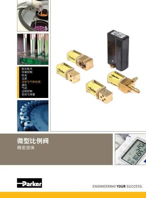
因此,请与派克合作,准备改变这一切吧!/precisionfluidics 1 603 595-1500电子压力控制目录产品页OEM-EP 4VSO ®-GC 10VSO ®-EP 16VSO ®-EV 22VSO ®-HP 27VSO ®-LP33微型电子压力控制器专为快速系统响应和最小内部体积而设计微型电子压力控制器专为精密气流控制和微型流量控制而设计高性能微型压力控制器专为实现高性能 (HP) 快速压力放气而设计微型电子压力控制器专为低流量控制而设计微型电子真空控制器专为精密真空控制而设计使用寿命长的微型压力控制器专为要求快速压力放气工业应用而设计APC38微型电子压力控制器专为低功耗、要求高准确度和分辨率的便携应用而设计4OEM-EP 压力控制器OEM-EP 微型电子压力控制器将可变的电子控制信号转换为可变的气动输出。
OEM-EP 设定成标准的型号来减小内部体积和方便集成,对于精确控制压力十分关键的手动调节器、针阀和通气孔,它是理想的替换品。
OEM-EP 采用派克汉尼汾获得专利的 VSO ® 比例阀和内部闭环控制,是载气流量控制、微型流量控制、真空泵控制以及吸入/分配液体应用的完美之选。
• 通过静音操作来降低系统的噪音水平• 通过高准确度和无可比拟的分辨率来改进成果• 经过测试表明,使用寿命长,系统可用性高• 通过内部闭环控制来缩短系统开发时间• 内部体积小,系统效率高• 通过模拟控制提高设计灵活性•符合 RoHS 指令特征物理特性电的性能特点微型电子压力控制器典型应用• 载气压力控制 • 气顶液流量控制• 质谱用气体源的压力控制与流体接触的材料PRESSURESENSOR6机械集成基本尺寸,OEM-EPMolex #874380642至引线插入式线缆(包括在内)电接口OEM-EP 微型电子压力控制器公制螺纹适配器(可选项)UNITS IN. [mm.]2 Body, Basic Valve Dimensions (2-Way and 3-Way).305 [7.75]1.46 [37.1]1.73 [43.9](2-WAY).055 [1.40]Ø.500 [Ø12.70](3-WAY, NORMALLY OPEN)2.44 [62.0]ELECTRICAL CONNECTOR OUTPUT.18 [4.6]#10-32 UNF-2B .18 [4.6]INLET (REQUIREMENT).16 [4.1]OEM-EP:7安装指南OEM-EP 是一种动态压力控制器,采用比例阀技术提供精确稳定的压力源,以满足各种应用 要求。
克林吊调试要点--Parker液压件一、准备工作1.注油1)油箱内清除干净后,用滤油小车(过滤精度20um)加入至少75%的液压油(请注意在基本动作正常后特别是变幅油缸动作后,在油缸全缩状态下,将油位补到75%)。
注意回油滤器、空气滤清器外壳的塑料包装膜不要忘记拆掉;最后清洁用的抹布、海绵、面粉团不要遗忘在油箱内2)所有油泵、油马达的壳体在开车前务必灌满干净之液压油3)所有减速机检查齿轮油是否注油到位4)塔身上变幅油缸销轴处、吊臂滑轮组及其他运动部位轮滑到位2.阀件开关状态检查1)打开油泵吸口蝶阀2)打开所有平衡阀块上的刹车回路节流阀3)关闭起升、变幅平衡阀块上应急下放节流阀4)打开回转平衡阀块A、B口高压球阀5)打开主泵压力表开关阀二、泵组启动1.点动启动电机,检查电机转向是否与油泵铭牌上转向一致。
点动运行几次,使油泵充分吸油2.空转运行泵组15分钟,作必要的跑和检查1)观察主泵压力值,在不操作任何电手柄时压力应该小于0.5MPa 2)油泵应无异常噪音3)在有泵壳冲洗回路情况下,泵壳温度不应超过70摄氏度4)在不操作任何电手柄情况下,手动顶泵口溢流阀组上电磁阀,此时泵组运行声音应明显降低、电机电流应基本与空转电流一致、泵口压力应在2.7-3MPa,如有需要请调节泵上压差阀。
*注:1)在此期间,若发现某个执行机构有误动作,则可能性最大的是多路换向阀组中控制此机构动作的比例先导阀卡住或堵塞,处理办法:在停机后2分钟后,拆掉比例阀的两个固定螺钉,一边旋转一边用力向上拔,将有故障可能的比例阀拆下,然后插上比例插头,用电控手柄操作,使比例阀能明显动作,同时将比例阀体(不包括线圈)浸入干净的煤油中漂涮,允许操作阀上的比例阀孔向外溢出油液,以保证阀控内可能存在的异物或杂质被冲走,重新安装比例阀后再观察故障是否排除,若还是同样的故障现象,请更换比例阀或检查相关的换向主阀芯(拆掉两头的比例阀盖板及闷盖板即可抽出主阀芯)是否有异物卡住而偏置《比例先导阀及盖板》注:2)若手顶泵组起压电磁阀后,压力无明显变化(即压力<0.5MPa),则泵组溢流阀内的阻尼孔堵塞的可能性较大请检查下列示意图中的阻尼孔(约0.8mm大小)《不起压力时检查阻尼口》5)因为在此15分钟空转运行期间,泵是在最大排量下卸荷经回油滤器回油的,所以可以达到对油箱内油液的初步过滤,是为后续的系统正常运行调试做好铺垫打好基础的,请务必在正式动车前执行此操作!三、压力设定1.在带压调试前,请先对多路换向阀组作初步设定,参考下列图片:《多路换向阀组初步设定-1》《多路换向阀组初步设定-2》2.泵组压力设定1)任意手柄刚刚离开中位时(操作角度不超过10度),泵组压力应该在2.7-3MPa,如果压力不符,请调整泵上压差阀;如果压力没有明显变化,则检查泵组起压电磁阀是否得电2)关闭回转平衡阀组上A、B口的球阀,先将泵上压力切断阀尽可能紧到底,操作回转动作,泵组压力应等于28.5MPa,请调整泵口溢流阀以达到此压力3)泵口溢流阀设定到28.5MPa后,将泵上压力切断阀调低至26MPa,此时电机电流约在140A左右3.泵组功率设定在额定拉力吊重试验条件下,在起升电控手柄达到最大起升操作角度后,调整泵上恒功率阀,使电机电流=298A以上2、3步骤泵组压力、功率设定请参考下列图片调试《泵组压力及功率设定示意图》四、起升变量马达的调整只有在40%的轻载条件下速度未能达到设计要求时,可以考虑调小起升变量马达的最小排量,但是前提是在快速状态下操作压力不大于25MPa五、起升压力开关设定由于起升绞车快速时的自动保护已由吊重指示器控制,在此情况下起升阀块上安装的压力开关作为1.1倍超载保护,所以压力设定应该等于26x1.1=28.6MPa,具体设定方法:在额定负载下慢速操作起升绞车上升,当钢丝绳刚刚绷紧后负载快要离地时,调节压力开关,使吊重报警指示灯及蜂鸣器报警,在此基础上多调紧一圈即可*注:1)在吊重试验前请先标定吊重指示器2)在吊重试验过程中,注意观察是否有过载报警,及时调整吊重超载设定值,以保证试验的安全。
PneumaticCatalog 0637-4/USA“B” SeriesAir Control ValvesB2 -.16 Cv M5, 1/8" Port B3 -.75 Cv 1/8", 1/4" Port B4 - 1.22 Cv 1/4" PortB5 - 1.40 Cv 1/4", 3/8" Port B6 - 2.70 Cv 3/8" Port B7 - 5.90 Cv 1/2" Port B8 -7.00 Cv3/4" PortIndexWARNINGFAILURE OR IMPROPER SELECTION OR IMPROPER USE OF THE PRODUCTS AND/OR SYSTEMS DESCRIBED HEREIN OR RELATED ITEMS CAN CAUSE DEATH, PERSONAL INJURY AND PROPERTY DAMAGE.This document and other information from Parker Hannifin Corporation, its subsidiaries and authorized distributors provide product and/or system options for further investigation by users having technical expertise. It is important that you analyze all aspects of your application including consequences of any failure, and review the information concerning the product or system in the current product catalog. Due to the variety of operating conditions and applications for these products or systems, the user, through its own analysis and testing, is solely responsible for making the final selection of the products and systems and assuring that all performance, safety and warning requirements of the application are met.The products described herein, including without limitation, product features, specifications, designs, availability and pricing,are subject to change by Parker Hannifin Corporation and its subsidiaries at any time without notice.Offer of SaleThe items described in this document are hereby offered for sale by Parker Hannifin Corporation, its subsidiaries or its authorized distributors. This offer and its acceptance are governed by the provisions stated on the separate page of this document entitled “Offer of Sale”.© Copyright 2001, Parker Hannifin Corporation. All Rights Reserved!IndexTable of Contents Air Control ValvesBasic Valve Functions4-Way Valves (2)3-Way Valves (3)Common Part Numbers ......................................................................................... 4-5 Model Number IndexesB2 Series (6)B3 Series (7)B4 Series (8)B5 Series (9)B6 Series (10)B7 & B8 Series (11)IEM Stackable ManifoldsManifolds & Kits (12)Ordering Information (13)Bar ManifoldsIEM Bar Manifolds (14)Subbase Aluminum Bar Manifolds (15)Ordering Information (16)AccessoriesSubbase & Manifolds (17)Sandwich Regulators (18)Featured Valve Options ...................................................................................... 19-20 Electrical Connectors / Accessories .................................................................. 21-22 Technical InformationTechnical Data (23)Solenoid Data (24)Pilot Configuration (25)Repair InformationSolenoid Kits (26)Exploded Views ............................................................................................. 28-33 Dimensions ........................................................................................................ 34-52 Definitions & Weights .. (53)Offer of Sale (56)Operator / Function 7#14Operator / Function 0CE#14APBSingle Solenoid4-Way, 2-PositionDe-energized position – Solenoid operator #14 de-energized.Pressure at inlet port 1 connected to outlet port 2.Outlet port 4 connected to exhaust port 5.Energized position – Solenoid operator #14 energized.Pressure at inlet port 1 connected to outlet port 4.Outlet port 2 connected to exhaust port 3.Double Solenoid4-Way, 2-PositionSolenoid operator #14 energized last. Pressure at inlet port 1connected to outlet port 4. Outlet port 2 connected to exhaust port 3.Solenoid operator #12 energized last.Pressure at inlet port 1connected to outlet port 2. Outlet port 4 connected to exhaust port 5.Single Remote Pilot4-Way, 2-PositionNormal position – Pressure at inlet port 1 connected to outlet port 2. Outlet port 4 connected to exhaust port 5.Operated position – Maintained air signal at port 14.Pressure at inlet port 1 connected to outlet port 4.Outlet port 2 connected to exhaust port 3.Double Remote Pilot 4-Way, 2-PositionMomentary air signal at port 14 last. Pressure at inlet port 1connected to outlet port 4. Outlet port 2 connected toexhaust port 3.Momentary air signal at port 12 last. Pressure at inlet port 1connected to outlet port 2. Outlet port 4 connected to exhaust port 5.Double Solenoid4-Way, 3-PositionDouble Remote Pilot4-Way, 3-PositionDual Pressure:May be used for dual pressure service with pressure at ports 3 & 5. (Use either external pilot source option “K”, “W” or “X”, or dual pressure pilot source option “D” or “E”.) If pilot source “D” or “E” is selected, the high pressure must be at port #3. If pilot source “K”, “W” or “X” is selected, the external pilot must be plumbed to port #14 or “X” respectively. NOTE: The “B6” valve is also available with dual pressure using Port 5 for high pressure (Option “G” & “H”). This is only to be used if converting from a “42” (“CM”) Series traditional valve.In the 3-Position valve, the effect of dual pressure is extremely important when the valve is in the center position, as the CEand PC functions are reversed. Therefore, care should be used when selecting a 3-Position valve.4-Way Valve FunctionsBasic Valve Functions#14#12#12#14#12With #12 operator signaled – inlet port 1 connected tocylinder port 2, cylinder port 4 connected to exhaust port 5.With #14 operator signaled – inlet port 1 connected tocylinder port 4, cylinder port 2 connected to exhaust port 3.Function 8: All Ports BlockedAll ports blocked in the center position.Function 9: Center ExhaustCylinder ports 2 and 4 connected to exhaust ports 3 and 5 in center position. Port 1 is blocked.Function 0: Pressure CenterPressure port 1 connected to cylinder ports 2 and 4, and exhaust ports 3 and 5 blocked in center position.With #12 operator energized – inlet port 1 connected to cylinder port 2, cylinder port 4 connected to exhaust port 5.With #14 operator energized – inlet port 1 connected to cylinder port 4, cylinder port 2 connected to exhaust port 3.Function 5: All Ports BlockedAll ports blocked in the center position.Function 6: Center ExhaustCylinder ports 2 and 4 connected to exhaust ports 3 and 5 in center position. Port 1 is blocked.Function 7: Pressure CenterPressure port 1 connected to cylinder ports 2 and 4, and exhaust ports 3 and 5 blocked in center position.#12#10Single Solenoid3-Way, 2-Position NCNormally Closed:De-energized position – Solenoid #12 de-energized.Pressure at inlet port 1 blocked, outlet port 2 connected to exhaust port 3.Energized position – Solenoid #12 energized.Pressure at inlet port 1 connected to outlet port 2,exhaust port 3 is blocked.Single Solenoid3-Way, 2-Position NONormally Open:De-energized position – Solenoid #10 de-energized. Pressure at inlet port 1 connected to outlet port 2,exhaust port 3 is blocked.Energized position – Solenoid #10 energized.Pressure at inlet port 1 blocked, outlet port 2 connected to exhaust port 3.Double Solenoid3-Way, 2-PositionSolenoid operator #12 energized last.Pressure at inlet port 1connected to outlet port 2, exhaust port 3 is blocked.Solenoid operator #10 energized last. Pressure at inlet port 1blocked, outlet port 2 connected to exhaust port 3.Single Remote Pilot 3-Way, 2-Position NCNormally Closed:Normal position – Pressure at inlet port 1 blocked,outlet port 2 connected to exhaust port 3.Operated position – Maintained air signal at port 12.Pressure at inlet port 1 connected to outlet port 2,exhaust port 3 is blocked.Single Remote Pilot3-Way, 2-Position NONormally Open:Normal position – Pressure at inlet port 1 connected to outlet port 2, exhaust port 3 is blocked.Operated position – Maintained air signal at port 10.Pressure at inlet port 1 blocked, outlet port 2 connected to exhaust port 3.Double Remote Pilot3-Way, 2-PositionMomentary air signal at port 12 last. Pressure at inlet port 1connected to outlet port 2, exhaust port 3 is blocked.Momentary air signal at port 10 last. Pressure at inlet port 1blocked, outlet port 2 connected to exhaust port 3.3-Way Valve / Dual 3/2 Valve FunctionsBasic Valve FunctionsDual 3-WayCombines the functions of T wo 3-Way valves into One valve body . The valve can be configured as Two Normally Closed 3-Way FunctionsTwo Normally Open 3-Way FunctionsOne Normally ClosedANDOne Normally Open 3-Way Functions42531#14#1242531#14#1242531#14#12#12#10#12#10#12#10#12#10#12Solenoid, 3-Way & 4-WayCommon Part NumbersSingle Solenoid4-Way, 2-PositionDouble Solenoid4-Way, 2-PositionSingle Solenoid3-Way, 2-Position, NCDouble Solenoid4-Way, 3-Position,APB3-Pin DIN 43650C Electrical Connection,Non-Locking Flush Override.InlineInlineInlineInline#12B3 thru B8B2 OnlyInternal Air Return Spring / Air Return#14B3 thru B8B2 OnlyInternal Air Return Spring / Air Return#12#10#12APB#12Remote Pilot, 3-Way & 4-WayCommon Part NumbersSingle Remote Pilot4-Way, 2-PositionDouble Remote Pilot4-Way, 2-PositionSingle Remote Pilot3-Way, 2-Position, NCDouble Remote Pilot4-Way, 3-Position, APBInlineInlineInlineInlineB3 thru B8B2 OnlyB3 thru B8B2 OnlyInternal Air Return Spring/Air ReturnInternal Air ReturnSpring/Air Return#12#10Basic Operator/Port Size/Pilot Source/Enclosures/EngineeringBasic Operator/Port Size/Pilot Source/Enclosures/EngineeringBasic Operator/Port Size/Pilot Source/Enclosures/EngineeringBasic Operator/Port Size/Pilot Source/Enclosures/EngineeringBasic Operator/Port Size/Pilot Source/Enclosures/EngineeringBOLD OPTIONS ARE STANDARDBasic Operator/Port Size/Pilot Source/Enclosures/EngineeringB7 & B8 SeriesIEM Stackable ManifoldsEnd Plate KitsTransition Plate Kit•Combines B3 and B5 4-Way valves into a common inlet and exhaust manifold system. Looking at the #12 end, the B5 is on the right and the B3 is on the left.•Kit includes: B3 end plate, B3/B5 transition plate, B5 end Kit includes: Right and Left End Plate, o-rings, socket head cap screws, flat washers and lockwashers.* B4 & B5 4-Way use the same Kit.ManifoldsIEM Stackable Manifolds & KitsStation Station Station Station 1234Example:Application requires a 4-station manifoldwith flow controls and requires isolationbetween station 2 & 3 for all three main galleys.Qty.Part No.Comment1AAB3FC04041B32FBD553C ..............Station 11B31FBE553C ..............Station 21PS2919P .....................Galley 1, 3, 5Between Station 2 & 31B31FBB553C ..............Station 31B35FBB553C ..............Station 414 End12 EndLooking at 12 EndIEM Stackable Add-A-Fold AssembliesOrdering InformationXXT otal Number of StationsNumber of Flow Controlbases in assembly (Omit if none)3-Way Valve B34-Way Valve 3-Way Valve B44-Way Valve B54-Way ValveAAAdd-A-Fold AssemblyHow To Order IEM Stackable Add-A-Fold Assemblies1.List Add-A-Fold Assembly call out.This automatically includes the end plate kit,manifold bases and assembly.2.List complete inline valve model number,listing left to right LOOKING A T THE #12 END of the manifold. The left most station is station 1.(If a blank station is needed, list theBlank Plate part number at the desired station.)*Flow control bases must start at station 1 in Add-A-Folds.Example: AAB3FC0206. Station 1 & 2 have flow controls, station 3 – 6 do not.B3B4B5B5 SeriesIEM Bar Manifolds (Inlet / Exhaust Manifold)Bar Manifolds35mm DIN 4-Way3-Way4-Way3-Way4-Way3-Way4-Way3-WayCylinder Port # of Model NumberSubbase Aluminum Bar Manifolds (5-Ported)Bar Manifolds•Utilizes Subbase mount B2 valves.•3-Way & 4-Way valves interchangeable.•External Pilot Valves – “X” or “W”, must be used.•Common External Pilot galley is field convertible from Internal to External Pilot.(Shipped as Internal Pilot from factory.)35mm DIN Rail MountInternal ExternalKit includes:Subbase –(1) manifold (bolts & gasket comewith subbase valve).•Utilizes Subbase mount B3 valves.•Available for 4-Way valves. If 3-Way function is required,plug a cylinder port.•Common External Pilot galley is standard.•Standard Internal Pilot valves need not use this galley,and the galley does not need to be plugged.•External Pilot Valves – “X” or “W”, must have Common External Galley pressurized.35mm DINHow To Order Aluminum Bar Manifold Assemblies1.List Manifold Assembly call out. Use AA +the part number of the aluminum bar manifold.This automatically includes the aluminum bar manifold and assembly.2.List complete valve model number, listing left toright, LOOKING AT THE #12 END of the manifold.The left most station is station 1.(If a blank station is needed, list the blanking plate part number at the desired station.)#12 End#14 EndExample:Application requires a 3-station “B3”3-Way manifold with station #1 blankedoff with valves assembled.Qty.Part No.Comment1AAPSG3BXN03NP1PS2966P .....................Station 11B330000XXC...............Station 21B3J0BB553C...............Station 3Station Station Station 123Looking at 12 EndAluminum Bar Manifold AssembliesOrdering InformationUse Aluminum Bar Manifold Kit Numbers from previous pages.Manifold AssemblySubbase / ManifoldsAccessoriesSubbaseBlanking PlateKit includes: (2) Screws, (2) Nuts, (2) ClampsDIN Rail Hardware Kit。
2024年液压比例阀市场前景分析引言液压比例阀是一种重要的控制元件,在液压系统中起到调整流量和压力的作用。
随着全球工业化进程的加速和机械化程度的提高,液压比例阀市场呈现出稳步增长的趋势。
本文将对液压比例阀市场前景进行分析。
市场规模与增长趋势液压比例阀市场的规模在过去几年里稳步增长。
据市场研究数据显示,2019年全球液压比例阀市场规模达到XX亿美元,预计到2025年将达到XX亿美元,年复合增长率为XX%。
这一增长趋势主要受到工业自动化和液压驱动设备需求的推动。
市场驱动因素工业自动化程度提高随着工业自动化程度的提高,对液压系统的需求也在增加。
液压比例阀作为液压系统中的关键控制元件之一,广泛应用于工业自动化设备中。
自动化设备的增加直接推动了液压比例阀市场的发展。
高效能需求全球范围内,能源效率和资源利用率的要求越来越严格。
液压比例阀作为一种高效能的控制元件,能够保证液压系统的精确控制和能量优化利用。
高效能要求驱动了液压比例阀市场的增长。
新兴市场需求增加新兴市场对液压比例阀的需求在不断增加。
这些市场发展迅速,工业化水平提高,对液压驱动设备和液压比例阀的需求不断增加。
中国、印度等新兴市场被认为是液压比例阀市场的重要增长驱动力。
市场竞争格局液压比例阀市场呈现出较为集中的竞争格局。
市场上的主要厂商包括Bosch Rexroth、Parker Hannifin、Eaton、Danfoss、Sun Hydraulics等。
这些公司通过不断创新和技术提升来提供高品质的液压比例阀产品,同时通过全球渠道网络拓展市场份额。
市场风险与挑战技术挑战液压比例阀的制造和应用对技术水平要求较高。
制造商需要不断改进和创新,提高产品的精度和可靠性,以满足市场需求。
此外,新兴技术如电液比例阀和伺服控制系统的发展也可能对传统液压比例阀市场造成冲击。
市场竞争压力液压比例阀市场竞争激烈,主要厂商之间的竞争压力不断增加。
价格竞争和品牌声誉成为影响厂商盈利能力的重要因素。
MV-20 1/4” - 1” Manual PTFE Distribution Valve Product OverviewThe MV-20 distribution valve is designed for use slurryapplications, and is also ideally suited for ultra-pure waterand aggressive chemical or gas applications. The designutilizes a machined PTFE body with precision machinedseat and diaphragm sealing areas. The valve is offered in3 orifice sizes (1/4”, 1/2” and 1”) and port sizes rangingfrom 1/4” to 1 1/4”.FeaturesFully swept open bowl diaphragm seat area.Self draining design.High load point seat seal. Angled and rounded internal flow path.One piece precision machined diaphragm manufactured from modified PTFE.Evenly distributed seat sealing forces.Maximized diaphragm thickness.BenefitsMinimizes fluid shear andsmooth flow transition.Minimizes area for entrapmentand stagnation of media.Improves sealing mechanismfor aggressive chemicals,deionized water and abrasiveslurry media.Minimizes particlecontribution of valve.Provides faster purging andcleaning of valve.Less pressure drop allows forlower pressure requirementsupstream.Improves fluid flow dynamics.Improves cycle life, less shearthan standard PTFE material,lower replacement costs, lessdowntime.Minimized diaphragm andvalve seat strain.Stabilizes valve back pressurecapability.Minimizes potential forpermeation while maximizingcycle life.SpecificationsMaterials of ConstructionWetted:PTFE, Modified PTFENon-wetted:PVDF, Viton, PTFE coated SS springPressure Ranges1/4” Orifice:27” HG vacuum (913 mbar) - 80 PSIG (5.5 bar)1/2” Orifice:27” HG vacuum (913 mbar) - 100 PSIG (7 bar)1” Orifice:27” HG vacuum (913 mbar) - 100 PSIG (7 bar)Pressure ranges for operation at ambient temperatures. Foruse at higher temperatures consult Pressure/Temperature charton page 3.T emperature RangesAmbient:0° - 150° F (-17° - 66° C)Fluid:0° - 266° F (-17° - 130° C)MV-20 1/4” - 1” Manual PTFE Distribution ValveG DPRE SS URE DROP V S . FLOW RATEFLOW RATE (lpm)FLOW RATE (g pm)D E L T A -P (p s i )D E L T A -P (b a r )0101020203030404050506060.71.42.12.83.54.23876113151189227M V -20-08-0608M V -20-08-0612M V -20-16-0612M V -20-16-0616M V-20-16-0620FLOW RATE (lpm)FLOW RATE (g pm)D E L T A -P (p s i )D E L T A -P (b a r )015210315420525630.34.691.01.41.72.13.87.611.315.118.922.7M V -20-04-0604M V -20-04-0606。
p a r k e r比例阀Parker比例阀中国石化镇海炼化年产一百万吨乙烯工程,六日在环杭州湾石化产业带南翼开工建设。
这一“世界级、高科技、一体化”的炼化项目总投资二百二十亿元人民币。
据了解,乙烯被称为“石化之母”,是石油化工的基础性原料,经过各种化学变化,可以“繁衍”出塑料、化纤、合成橡胶等种类繁多的化学制品,关系到一个国家或地区的经济发展水平。
到二00五年,中国乙烯生产能力已跃居世界第二位,仅次于美国。
中国石化镇海炼化年产一百万吨乙烯工程是浙江省首个乙烯工程,包括大型乙烯和配套热电扩建工程,产品都为国内缺口较大的品种,符合浙江省及周边地区的市场需求。
首页>>产品中心>>YB43X固定比例式减压阀一、产品[固定比比例式减压阀]的详细资料:产品型号:YB43X产品名称:固定比比例式减压阀产品特点:固定比比例式减压阀,比例式减压阀,减压阀公称通径DN lmmlA D325 232 115/12532 246 140/15040 256 150/15550 270 165/17565 306 185/20080 320 210/230100 340 240/265 125 400 275/300 150 429 310/350 200 358 355/400型号公称压力PN(MPa)公称通径DN(mm) LYB43X-10T (B型) 1.0 50 85 65 102 80 122 100 140 125 160 150 178 200 230YB43x-16T (B型) 1.6 50 85 65 102 80 122 100 140 125 160 150 178 200 230四、YB43X固定比例式减压阀外形尺寸:公称通径尺寸(mm)DN Imm) C L D15 1/2″80 5020 3/4″80 5025 1″90 5432 11/4″100 6040 11/2″110 6850 2″120 80订货须知:一、①YB43X固定比例式减压阀产品名称与型号②YB43X固定比例式减压阀口径③YB43X固定比例式减压阀是否带附件二、若已经由设计单位选定公司的YB43X固定比例式减压阀型号,请按YB43X固定比例式减压阀型号三、当使用的场合非常重要或环境比较复杂时,请您尽量提供设计图纸和详细参数,相关产品:WM341系列隔膜可调式减压阀波纹管式减压阀T44H/Y型波纹管减压阀YZ11X直接作用薄膜式水用减压阀直接作用薄膜式减压阀内螺纹活塞式蒸汽减压阀Y45H/Y型手动双座蒸汽减压阀Y945H/Y型电动双座蒸汽减压阀高灵敏度蒸汽减压阀铜阀门>>铜减压阀>>全铜比例式减压阀产品名称:全铜比例式减压阀产品型号:Y43X产品口径:DN50-200产品压力:0.6~10.0MPa产品材质:铸铁、铸钢、不锈钢等产品概括:生产标准:国家标准GB、机械标准JB、化工标准HG、美标API、ANSI、德标DIN、日本JIS、JPI、英标BS生产。
阀体材质:铜、铸铁、铸钢、碳钢、WCB、WC6、WC9、20#、25#、锻钢、A105、F11、F22、不锈钢、304、304L、316、316L、铬钼钢、低温钢、钛合金钢等。
工作压力1.0Mpa-50.0Mpa。
工作温度:-196℃-650℃。
连接方式:内螺纹、外螺纹、法兰、焊接、对焊、承插焊、卡套、卡箍。
驱动方式:手动、气动、液动、电动。
产品详细信息全铜比例式减压阀:比例式减压阀,体积小,外形美观,质量可靠,具有流量大,灵敏度高,开启自如等特点,克服了内压比例阀水压通过活塞时形成的涨力,摩擦力大的缺点,使其性能更加稳定,使用寿命更长活塞运动自如,流体不隔层通过,提高了介质适用温度。
该产品分为2:1、3:1、3:2比例式减压阀主要技术参数型号公称压力PN(MPa)公称通径DN(MM)LY43X-10T(B型) 1.050 85 65 102 80 122 100 140 125 160 150 178 200 230Y43X-16T 1.650 85 65 102 80 122 100 140 125 160 150 178 200 230三、比例式减压阀主要外形尺寸(法兰连接尺寸PN1.0MPa按GB4216.4-84标准,PN1.6MPa 按GB4216.5-84标准)公称通径DN(MM)尺寸(MM)C L D15 1/2" 80 50 20 3/4" 80 50 25 1" 90 54 32 1 1/4" 100 60 40 1 1/2" 110 6850 2" 120 80减压阀>>比例式减压阀>>比例式减压阀产品名称:比例式减压阀产品型号:Y43X产品口径:DN25-200产品压力:1.6-6.4Mpa产品材质:铸钢、不锈钢、合金钢等产品概括:生产标准:国家标准GB、机械标准JB、化工标准HG、美标API、ANSI、德标DIN、日本JIS、JPI、英标BS生产。
阀体材质:铜、铸铁、铸钢、碳钢、WCB、WC6、WC9、20#、25#、锻钢、A105、F11、F22、不锈钢、304、304L、316、316L、铬钼钢、低温钢、钛合金钢等。
工作压力1.0Mpa-50.0Mpa。
工作温度:-196℃-650℃。
连接方式:内螺纹、外螺纹、法兰、焊接、对焊、承插焊、卡套、卡箍。
驱动方式:手动、气动、液动、电动。
产品详细信息Y43X比例式减压阀概述我公司生产的比例式减压阀,外形美观、质量可靠,比例准确,工作平稳,既减动压也减静压。
该阀利用阀体内部活塞两端不同截面积产生的压力差,改变阀后的压力,达到减压目的。
我公司减压阀的减压比例是:2∶1,3∶1,4∶1,3∶2,5∶2等,亦可根据用户的要求设计特殊比例的减压阀。
主要技术参数适用介质水、气体适用温度≤90℃压力误差≤8%最小开启压力2∶1 0.2MPa 3∶1 0.3MPa连接形式法兰、内螺纹主要零件阀体锡青铜不锈钢铸铁50 2" 120 80首页>>产品中心>>比例式减压阀一、产品[固定比例式减压阀]的详细资料:产品名称:固定比例式减压阀产品特点:本厂生产的比例式减压阀,外形美观,质量可靠,比例准确,工作平稳.既减动压也减静压。
该阀利用阀体内部活塞两端不同截面积产生的压力差,改变阀后的压力,达到减压目的。
我厂减压阀的减压比例是:2:1,3:1,4:1,3:2,S 2等,亦可根据用户的要求设计特殊比例的减压阀.固定比例式减压阀,减压阀。
适用介质水、气体适用温度≤90℃压力误差≤8%最小开启2:1 0.2MPa压力3:1 0.3MPO连接形式法兰、内螺纹主要零件阀体锡青铜不锈钢铸铁材料内件锡青铜不锈钢锡青铜或不锈钢三、比例式减压阀主要外形尺寸(法兰连接尺寸PNl.OMPa按GB4216.4—84标准):公称通径DN (mm)A125 11532 12440 13250 14065 15580 155100 200125 220150 230200 270订货须知:一、①比例式减压阀产品名称与型号②比例式减压阀口径③比例式减压阀是否带附件二、若已经由设计单位选定公司的比例式减压阀型号,请按比例式减压阀型号三、当使用的场合非常重要或环境比较复杂时,请您尽量提供设计图纸和详细参数,相关产品:WM341系列隔膜可调式减压阀波纹管式减压阀T44H/Y型波纹管减压阀YZ11X直接作用薄膜式水用减压阀直接作用薄膜式减压阀内螺纹活塞式蒸汽减压阀Y45H/Y型手动双座蒸汽减压阀Y945H/Y型电动双座蒸汽减压阀YB43X固定比例式减压阀高灵敏度蒸汽减压阀各种气体专用阀门>>燃气专用阀>>天然气减压阀产品名天然气减压阀称:产品型YK42F号:产品口DN20-400径:产品压1.6-6.4Mpa力:产品材铸钢、不锈钢、合金钢等质:产品概括:生产标准:国家标准GB、机械标准JB、化工标准HG、美标API、ANSI、德标DIN、日本JIS、JPI、英标BS生产。
阀体材质:铜、铸铁、铸钢、碳钢、WCB、WC6、WC9、20#、25#、锻钢、A105、F11、F22、不锈钢、304、304L、316、316L、铬钼钢、低温钢、钛合金钢等。
工作压力1.0Mpa-50.0Mpa。
工作温度:-196℃-650℃。
连接方式:内螺纹、外螺纹、法兰、焊接、对焊、承插焊、卡套、卡箍。
驱动方式:手动、气动、液动、电动。
产品详细信息一、产品用途:YK42F系列天然气减压阀是弹簧薄膜式减压的换代产品,与薄膜式相比有以下优点:1、使用寿命长,不存在膜片损坏的问题。
2、耐高压,出口压力高时,薄膜片高不行了,而活塞可适应很高的出口压力。
该阀用于工作温度-10~150℃的天然气和空气,燃气,非腐蚀性液体管路上,在高层建筑的冷热供水和消防供水的系统中,可取代常规分区水管,这样可以简化的节省系统的设备,降低工程造价,也可在各类压机设备的冷却系统中起着减压、稳压作用,的确是用户理想的产品。
二、工作原理:1、本阀通过启闭件的节流,造成压力损失迫使进口压力在出口处降低某一个需要值,当流量和压力变化时,利用本身介质能量来控制出口压力基本不变的目的。
2、本阀介质走向由上进下出,当调节出口压力时,顺时针旋转调节螺栓迫使活塞向下移动,打开主阀,改变节流面积,造成压力损失,实现减压。
由于阀后介质通过“X”通道流入活塞下腔并与活塞上方保持平衡,当压力和流量变化时,使主阀节流面积始终保持相应位置,由于本阀采用卸荷机构,减小了进口压力面积,从而减小了阀门出口压力偏差,大大提高了减压阀的稳压精度。
三、性能规范:单位:MPa公称压力PN 试验压力PS进口压力P1出口压力P2最小压差△P背压PB压力特性△P2P1流量特性△P2G21.62.4 <1.6 0.1~1.0 0.2 ≤0.15 P2×10%P2×20%2.53.75 <2.5 0.3~1.6 0.2 ≤0.25 P2×10%P2×20%4.0 6.0 <4.0 0.3~2.5 0.2 ≤0.25 P2×10%P2×20%6.4 9.6 <6.4 0.5~3.0 0.25 ≤0.4 P2×12%P2×25%四、主要外形尺寸DNL H1 H2PN16 PN25 PN40 PN64 PN16 PN25 PN40 PN64 PN16 PN25 PN40 PN6420 160 160 170 90 90 90 90 220 220 220 220 25 180 200 200 95 95 105 105 255 255 265 365 32 200 220 220 100 100 110 110 255 255 265 365 40 220 240 240 115 115 130 130 325 325 330 330 50 250 270 270 120 120 135 135 325 325 330 330 65 260 280 300 125 126 145 145 330 330 340 355 80 310 330 330 135 135 160 160 340 340 340 340 100 350 380 380 185 185 185 185 360 360 360 360 125 400 450 450 190 200 200 245 560 560 565 565 150 450 500 500 205 210 240 280 580 580 585 585 200 500 560 560 220 245 245 310 630 630 635 635 250 600 270 750300 800 310 780350 850 390 850400 900 420 925减压阀>>活塞式减压阀>>先导活塞式气体减压阀产品名称:先导活塞式气体减压阀产品型号:YK43F产品口径:DN15-500产品压力:1.6-16.0Mpa产品材质:铸钢、不锈钢、合金钢等产品概括:生产标准:国家标准GB、机械标准JB、化工标准HG、美标API、ANSI、德标DIN、日本JIS、JPI、英标BS生产。