无线数据采集系统设计设计开题报告
- 格式:doc
- 大小:105.00 KB
- 文档页数:7

无线数据传输系统设计开题报告
吉林化工学院信息与控制工程学院
毕业设计开题报告
基于单片机的无线数据传输系统设计
Design of the Wireless Data Transmission System Based on Chip
Microcomputer
学生学号:11510225
学生姓名:高海昌
专业班级:自动1102
指导教师:李楠
职称:讲师
起止日期:2015.03.22~2015.04.03
吉林化工学院
Jilin Institute of Chemical Technology
说明:
1. 本报告前6项内容由承担毕业论文(设计)课题任务的学生独立撰写;
2. 本报告必须在第八学期开学三周内交指导教师审阅并提出修改意见;
3. 学生须在小组内进行报告,并讨论;
4. 本报告作为指导教师、专业系或毕业论文(设计)指导小组审查学生能否承担该毕业设计(论文)
课题和是否按时完成进度的检查依据,并接受学校和教学院的抽查。
基于无线传感器网络的数据采集系统的设计与实现的开题报告一、选题背景和意义随着科技的不断发展和应用,传感器技术已经成为了物联网的重要组成部分。
无线传感器网络作用于及其广泛,在监测环境变化、健康监测、车联网等多个领域都有着重要的应用。
数据采集系统则是无线传感器网络不可或缺的组成部分。
对数据采集系统的研究探讨能够提升无线传感器网络的性能和稳定性、提高信息收集和传输的效率,加快数据分析和共享的速度,对于促进现代化信息技术的发展和普及,具有非常重要的意义。
二、研究内容本次研究主要针对无线传感器网络中的数据采集系统进行设计和实现,具体涉及以下内容:1. 无线传感器网络数据采集系统的概述:包括无线传感器网络技术的基本概念、传感器节点的性能与功能等方面的介绍。
2. 无线传感器网络数据采集系统的需求分析:分析数据采集系统的需求,并对数据采集系统中可能存在的问题进行初步探讨。
3. 无线传感器网络数据采集系统的设计:设计无线传感器网络数据采集系统的架构,确定系统工作流程,设计传感器节点的独特标识和数据采集协议,实现数据采集、压缩、存储、传输等功能。
4. 无线传感器网络数据采集系统的实现:利用无线传感器网络开源硬件平台和软件平台实现数据采集系统的功能,同时通过实验测试数据采集系统的稳定性和可靠性。
5. 结果分析和总结:根据实验结果和采集数据对数据采集系统进行进一步的分析和总结,升华出本次研究的成果和贡献。
三、研究难点及解决方案在进行无线传感器网络数据采集系统的设计和实现时,存在着一些难点和问题:1. 网络拓扑:如何设计合理的网络拓扑,避免信号干扰和数据丢失。
2. 传输协议:如何设计高效和安全的数据传输协议,保证数据的可靠性和安全性。
3. 数据存储和处理:如何实现大量数据的存储和处理,以便于后续的分析和利用。
4. 系统的稳定性和可靠性:如何保证数据采集系统的稳定性和可靠性。
针对以上问题,我们可以采用以下的解决方案:1. 网络拓扑方案应根据实际需求和环境特点进行适当调整,例如采用分簇的方式进行网格布局,减少传输距离和信号干扰。
无线数据采集与传输机制研究的开题报告一、研究背景与意义随着物联网技术的快速发展,物联网应用越来越广泛。
传感器网络是物联网的重要组成部分,而数据采集与传输是传感器网络中至关重要的环节。
传统的有线数据采集和传输方式往往受到设备布局、距离和环境等操作条件的限制,无法满足实际需求。
无线数据采集与传输技术能够克服传统方式的限制,具有传输速度快、网络布局灵活、易于实现等优势,被广泛应用于物联网领域。
本课题旨在深入探究无线数据采集与传输技术,针对传感器网络中的数据采集和传输问题,设计合适的无线数据采集方案,提高数据传输效率,实现数据信息化管理。
二、课题研究内容本课题将围绕传感器网络中无线数据采集与传输机制展开研究,具体内容包括:1. 无线数据采集技术研究介绍各种数据采集技术,包括基于无线传感器网络的数据采集技术,宽带无线数据采集和传输技术等。
2. 无线数据传输技术研究探究各种无线数据传输技术,包括Wi-Fi技术、蓝牙技术、ZigBee技术、LoRa技术以及NB-IoT技术等,研究各技术的特点、优点和适用范围。
3. 传感器网络中数据采集和传输方案设计结合传感器网络的实际情况,设计合适的无线数据采集和传输方案,包括网络拓扑结构设计、数据采集协议设计、数据传输协议设计等。
4. 数据传输效率分析和优化研究各种数据传输机制对网络性能的影响,分析数据传输效率,并通过优化数据传输协议等方式提高网络传输效率和数据传输质量。
三、研究方法1. 文献调研法:利用图书馆、网络等渠道收集相关文献,系统地进行调研和分析,了解无线数据采集与传输技术发展现状、研究热点和前沿进展。
2. 实验研究法:通过搭建实验平台,模拟实际网络环境,利用各种数据采集和传输技术进行测试,分析性能数据,优化数据传输方案,提高网络传输效率。
四、预期研究结果本课题的预期研究结果包括:1. 对无线数据采集和传输技术的现状和未来发展趋势的了解和把握。
2. 针对传感器网络中的数据采集和传输问题,提出合理、有效的无线数据采集和传输方案。
小型训练场无线数据采集与处理系统设计的开题报告一、研究背景小型训练场是一种用于进行各种机器人或无人机等设备的测试和训练的场地,其规模相对较小,但在机器人或无人机等设备领域有着广泛的应用。
在实际的训练场中,数据采集和处理系统起着至关重要的作用,可以帮助训练者分析和评估设备的性能,进而优化训练策略,提高训练效果。
目前市场上的小型训练场数据采集系统多数是基于有线连接的,但这种方式限制了设备的灵活性和可移动性,同时也增加了系统的构建成本。
因此,设计一种无线数据采集和处理系统来解决这些问题具有重要意义。
二、研究目的与意义本课题旨在设计一种可以在小型训练场中进行无线数据采集和处理的系统,以提高训练效果。
研究的主要目的如下:1.设计一套无线数据采集和处理系统,以提高设备的灵活性和可移动性。
2.通过该系统对机器人或无人机等设备的性能进行实时监测和分析,提供诊断和优化建议。
3.降低小型训练场数据采集系统的构建成本。
通过实现上述目标,本研究可以为小型训练场的应用提供更加高效、灵活和经济的解决方案。
三、研究内容和技术路线1.研究小型训练场数据采集和处理技术的基本原理和方法。
2.设计无线数据采集和处理系统中各个模块的硬件和软件结构,并完成模块之间的通信协议,实现数据的实时采集和处理。
3.测试和优化系统的性能,如最大数据传输速度、稳定性等。
4.针对实际应用需求进行系统的优化和升级。
技术路线如下:1.确定系统需求和目标,分析可行性。
2.研究和选取合适的无线数据传输协议,确定系统通信方式。
3.研究无线传感器网络结构、数据采集指标和一些安全措施。
4.设计各个模块的硬件和软件结构,提出更加合适的NBIOT网络通信协议,考虑数据的实时采集和处理。
5.测试系统,分析系统性能并进行优化。
6.分析实际应用场景,针对不同场景进行系统优化。
四、预期研究结果和应用价值预期研究结果如下:1.设计一套功能完善、性能稳定的小型训练场无线数据采集和处理系统。
录井通用无线数据采集与传输系统的研制的开题报告一、课题背景随着石油勘探技术的不断发展,钻井技术的发展也变得越来越先进。
录井是指在钻井过程中对井壁的一系列物理性质进行测量和记录,并将数据传递给地面进行分析和处理,从而提高油气勘探效率和成功率。
传统的录井数据采集与传输系统采用有线方式,不仅需要布置大量的电缆,而且在使用过程中容易出现故障和断电。
因此,开发一种无线数据采集与传输系统成为了解决这些问题的重要途径。
现代无线通信技术和传感器技术的不断发展,使得无线数据采集与传输系统的应用越来越广泛。
本课题旨在开发一种适用于录井的无线数据采集与传输系统,实现录井过程中的高效采集数据和远程传输数据,提高钻探效率和节约成本。
二、课题研究的意义当前传统的录井数据采集与传输系统采用有线方式,需要布置大量的电缆,并且在使用过程中容易出现故障和断电,从而影响钻井进展。
而无线数据采集与传输系统可以解决这些问题,从而提高录井效率和成功率。
本课题研究的无线数据采集与传输系统,可以促进录井技术的发展和更新,提高录井数据的采集精度和传输速度,使得录井处理更加高效和精确,为油气勘探提供更好的技术支持。
三、研究目标与内容本研究旨在开发一种适用于录井的无线数据采集与传输系统,研究内容包括:1. 系统架构设计:设计无线传感器节点、数据采集模块、数据处理模块、数据显示模块等模块,并对系统实现进行统一架构设计;2. 无线传感器设计:设计便携式、低功耗、高灵敏度录井传感器,包括钻井深度、井壁压力、井壁温度、井壁密度、液位等参数的测量;3. 无线通信协议设计:研究并设计适用于录井数据传输的无线通信协议,保证数据传输的高效、准确和安全性;4. 数据处理与管理:通过云计算技术,实现数据的统一管理和处理,并开发相应的数据分析工具;5. 系统集成与实现:将上述模块进行集成,并进行系统实现和测试。
四、研究方法本研究主要采用以下方法:1. 调研:调研目前国内外无线数据采集与传输技术的发展现状和趋势,对比分析钻井现场的电缆布置情况和实际需求,掌握录井数据采集和传输的技术现状和发展方向。
信号采集与分析系统的研究与开发的开题报告一、课题背景随着信息技术和物联网的发展,信号采集与分析系统在社会和工业领域中的应用越来越广泛。
信号采集与分析系统主要用于对各种信号进行采集、处理以及分析,例如声音、光电信号、电子信号等。
这些信号的采集和分析对于实现智能控制、运营管理和产品质量控制等方面具有重要作用。
本研究旨在开发一种高效、精确的信号采集与分析系统,以满足不同领域的需求。
二、研究目标本研究的目标是开发一种高效、精确的信号采集与分析系统。
具体包括以下几个方面:1.设计和开发信号采集硬件,实现对多种信号的采集和处理;2.设计和实现信号处理算法,提高信号处理的效率和精度;3.开发用户界面,实现对信号采集和分析的可视化操作。
三、研究内容1.信号采集系统的设计与开发本研究将设计并制造一种信号采集硬件,以实现对多种信号的采集和处理。
信号采集硬件将包括A/D转换器、信号放大器、低通滤波器等组件,以实现对信号的高质量采集。
同时,将通过接口设计实现硬件的互联与管理。
2.信号处理算法的设计与实现本研究将开发一些主要的信号处理算法,例如FFT、K-means聚类算法、小波变换等,用于对采集的信号进行处理和分析,从而获取更加精确和科学的数据。
同时,将对这些算法的效率和准确性进行优化,并将其整合到系统中。
3.用户界面的开发与实现为了方便用户对信号采集和分析的操作,本研究将设计并开发一个友好的用户界面,实现对操作过程的可视化操作。
用户界面将包括数据可视化、任务管理、数据存储等功能,以实现系统的高效性和实用性。
四、研究方法1.文献调查对相关文献进行调查和研究,并对现有的信号采集和处理技术进行概述和分析。
2.硬件设计基于市场上的成熟方案,设计并自行制造出符合实际需求的信号采集硬件,并进行实验和测试。
3.算法开发在调研的基础上,开发适合本系统特点的信号处理算法,提高处理效率和准确度。
4.用户界面开发在图形界面技术的基础上,设计出美观实用的用户界面,并与实际系统进行关联。
基于RF的无线数据传输系统的设计的开题报告一、课题背景及意义随着物联网、移动互联网等技术的快速发展,无线通信技术在各个领域都得到了广泛应用,特别是在智能家居、智能医疗、智能交通、农业监测等领域,更是需要具备低功耗、远距离传输、高速传输、抗干扰等特点的无线数据传输技术支持。
基于RF的无线数据传输系统满足了这些需求,因此在现代化生产生活中广泛应用,成为新一代无线通信技术的重要组成部分。
本课题旨在设计基于RF的无线数据传输系统,通过对系统的设计、实现及测试验证,为国内外企业提供可靠的基于RF的无线数据传输解决方案。
二、研究内容1. RF无线通信原理的研究;2. 基于RF的无线数据传输系统的设计;3. 系统硬件及软件的实现;4. 系统性能测试及数据分析。
三、研究方法1. 文献调研法:收集国内外RF无线通信技术的研究成果,深入了解基于RF的无线数据传输系统的技术原理、研究现状和发展趋势;2. 系统设计法:通过对基于RF的无线数据传输系统的功能和性能的要求,构建系统的功能模块、数据传输方式、数据地图等关键要素的设计方法;3. 系统实现方法:根据设计的模块,利用模块化设计原则和现有的通信模块、传感器等硬件元件,完成系统硬件及软件的实现;4. 系统测试方法:通过实验室里的测试设备,分别测试系统的数据传输速率、通信距离、稳定性等性能指标,并对测试数据进行分析。
四、预期成果1. 完成基于RF的无线数据传输系统的设计和实现;2. 验证系统在不同场景下的性能指标;3. 提供基于RF的无线数据传输解决方案,为厂商和企业提供参考。
五、进度安排1. 2月:完善开题报告,包括调研和系统设计;2. 3-5月:系统实现和功能测试;3. 6月:性能测试及数据分析;4. 7月:论文撰写和答辩准备。
六、存在的问题及后续建议本课题研究难度较大,需要投入大量的时间和精力。
其中如PCB设计以及不同硬件模块的连接互通等,都需要专业的硬件设计人员。
基于无线传感器网络的数据采集技术研究的开题报告一、研究背景与意义随着现代科技的不断发展和人们对信息处理和管理的需求不断增加,无线传感器网络(Wireless Sensor Networks, WSN)已经成为目前互联网、物联网等领域研究的重要方向之一。
WSN是由许多传感器节点构成的分布式系统,能够对周围的环境进行数据采集、处理、传输和控制,因此在环境监测、农业、医疗、安防等领域都有广泛应用。
在WSN中,数据采集是一个非常重要的环节。
目前,传统的数据采集方式采用有线连接,成本较高,操作不灵活,容易受到环境影响。
而无线传感器网络正好能够解决这些问题,但是如何在无线传感器网络中实现高效、准确的数据采集,仍然是一个亟待解决的问题。
因此本文旨在研究基于无线传感器网络的数据采集技术,为WSN的应用提供技术支持,为推动物联网技术的发展做出一定的贡献。
二、研究内容1、WSN基础知识概述介绍WSN的基础知识,包括WSN的发展历程、WSN的结构、传感器节点的功能及通信方式等。
2、数据采集模型设计本研究将设计一种基于数据流模型的数据采集模型。
该模型是基于数据流处理的方式进行设计,通过对传感器数据进行处理和编码,达到降低传输数据的信息冗余,提高数据传输效率的目的。
3、数据采集协议设计针对现有的数据采集协议存在的问题,本研究将设计一种特定的数据采集协议,以提高数据采集效率和准确性。
该协议将重点考虑传输的效率和网络的负载均衡问题。
4、实验设计本研究将在模拟实验中对设计的数据采集模型及协议进行测试,并对实验结果进行分析与比较。
三、研究计划1、第一阶段:调研与文献综述时间:2022.01-2022.03任务:调研WSN的相关知识及数据采集技术,阅读相关文献,明确研究思路和设想。
2、第二阶段:数据采集模型设计时间:2022.04-2022.06任务:设计基于数据流模型的数据采集模型,包括数据处理和编码等。
3、第三阶段:数据采集协议设计时间:2022.07-2022.09任务:设计一种特定的数据采集协议,以提高数据采集效率和准确性。
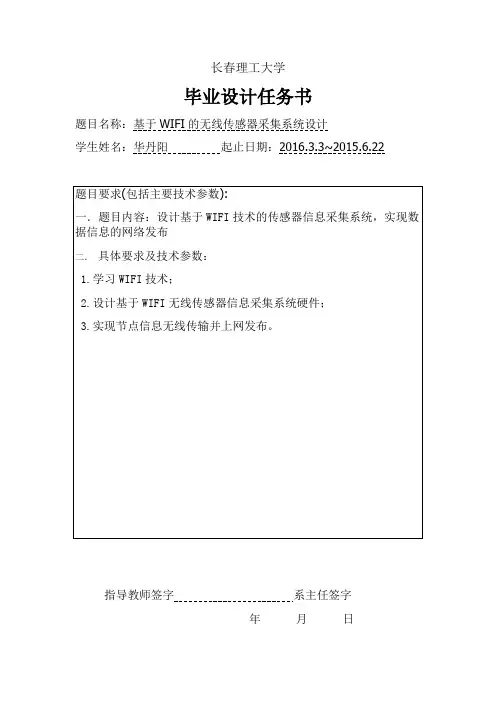
长春理工大学毕业设计任务书题目名称:基于WIFI的无线传感器采集系统设计学生姓名:华丹阳起止日期:2016.3.3~2015.6.22指导教师签字系主任签字年月日II. RELATED WORKPrior work in optical wireless using visible light that use photodiode receivers or imaging receivers are either limited to short ranges or require complex processing at the receiver [17], [21], [22]. Though photo diodes can convert pulses at very high rates, they suffer from large interference and background light noise. This results in very low SNRs and thus short communication ranges. We showed analytically in [6], based on the visual MIMO concept, that a camera receiver outperforms photodiode receivers in terms of its channel capacity at medium to long ranges. Recently, a few sporadic projects have begun to investigate cameras as receivers, particularly for inter-vehicle communications [21] and traffic light to vehicle communications [8]. Their analytical results show that communication distances of about 100m with a BER10 6 are possible. Other work has investigated channel modeling [18] and multiplexing [7]. While earlier work has also used cameras to assist in steering of FSO transceivers [25], the visual MIMO approach differs by directly using cameras as receiver to design an adaptive visual MIMO system that uses multiplexing at short distances but still can achieve ranges of hundreds of meters in a diversity mode.Only a few projects till now have investigated MIMO techniques for optical wireless. For shorter range systems [15], [26] show a MIMO approach for indoor optical wireless communication, [13] studied the capacity of a optical MIMO system and [19] details some work on space-time codes for optical MIMO. Earlier work by Kahn [23] investigates the use of multibeam transmitters and imaging receivers in Infra-Red systems very similar to MIMO in concept. Very recently the PixNet project [20] presents an implementation of an LCD - camera communication system that can deliver high data rates of the order of Mbps over distances of about 16m and wide view angles. PixNet uses OFDM to transmit between the LCD-camera pair similar to the pixelated - MIMO system proposed by Hranilovic and Kschischang [13]. In this paper we will emphasize that regardless of any type of modulation and transmission scheme, visual MIMO can still achieve significantly high data rates by exploiting some of the uniquecharacteristics of the visual channel.III. VISUAL MIMO MODELIn the visual MIMO communications system, the optical transmit element generates a light beam (optical signal) whose output power is proportional to the electrical input power of the modulating signal, limited by the emitter’s peak transmission power [14], [18], [22]. While RF channels are typically characterized by their impulse response that reflects the multipath environment, this aspect differs significantly for optical channels. Since the rate of change of the channel impulse response is very slow compared to the frequency of the optical signal, it is usually sufficient to use a static parameter (channel DC gain) [16] to represent the channel. For the same reason inter-symbol interference and multipath fading can be neglected in optical wireless channels. Similarly Doppler shift is negligible compared to the frequency as well.Consider the visual MIMO communication system model as shown in Fig. 1 where an opticaltransmitter consisting of an array of K transmitting elements communicates to a camera receiver with an array of I J pixels. The channel model for the visual MIMO system is given as,where Y 2 RI J is the image current matrix with eachelement representing the received current y(i; j) in each pixel with image coordinates (i; j), xk 2 R represents the transmitted optical power from kth element of the LEA and Hk 2 RI J is the channel matrix of the kth transmit element of the LEA, with elements hk(i; j) representing the channel between the kth transmit element and pixel (i; j), and N is the noise matrix. Noise in optical wireless is dominated by shot noise from background light sources and typically modeled as AWGN [16], [18]. Each element n(i; j) of the noise matrix N representing the noise current at each pixel is given aswhere q is the electron charge, R is the responsitivity of the receiver characterized as the optical power to current conversion factor, Pn is the background shot noise power per unit area, s is the square pixel side length and W is the sampling rate of the receiver (equates to the frame rate of the camera).The optical signal from the kth transmit element (k =1; 2; 3 : : :K) emitting a light beam of power Pin;k will be transmitted into the channel. At the receiver, depending on the focusing of the camera and the distance between the transmitting element and the camera, the transmitting element’s image may strike a pixel or a group of pixels of the detector array. The signal current in each pixel will depend on the concentration of the received signal component on that pixel which can be quantified as the ratio of the pixel area relative to the area spanned by the transmitting element’s image on the detector. If ck(i; j) represents the concentration ratio of the kth transmit element of an LEA on pixel (i; j), the channel DC gain hk(i; j) from each transmit element k to the pixel(i; j) is given aswhere R is the responsitivity, Ro( ) is the Lambertian radiation pattern of the optical transmitting element [16] with half-power angle , Alens is the area of the camera lens, is the camera field-of-view (fov) and dk;i;j , -k;i;j are the distance & viewing angle between each transmit element kand receiving pixel (i; j) respectively.Typically, since the pixel size is very small (order ofmicrons), the difference in distance dk;i;j and the viewing angle -k;i;j between each element of the transmitter array and every pixel is negligible. Therefore we refer to the distance dk;i;j = d and the viewing angle -k;i;j = - as the perpendicular distance and the angle between the transmitter array and image detector planes respectively. Hence the channel between each transmit element k and each pixel (i; j), characterized by hk(i; j), is primarily dependent on the concentration ratio ck(i; j) which can expressed as,where, s, f, lk are the pixel edge length, camera focal length and diameter of kth transmit element (considering a circular transmitting element) respectively. The amount of concentration of the signal per pixel is also dependent on the amount of blur in the image due to the lens. Typically, lens blur is modeled as a Gaussian function [12] and the amount of blur in the image is quantified by its standard deviation ( blur). The lens essentially acts like a filter with the blur function as its impulse response. Thus the image of the transmit element can be viewed as a result of the projected image convolving with the blur function over the detector area.I(:) is an indicator function indicating whether a pixel (i; j) receives a signal from the transmit element k or not, and is referenced in terms of the distance from pixel at the center of the transmit element’s image (irefk ; jrefk ). Given the spatial coordinates of the transmitting elements of an LEA with respect to the camera reference we can determine the image center coordinates of those transmit element through optical ray-tracing techniques in conjunction with some basic computer vision theory [9].IV. PERSPECTIVE DEPENDENT MIMO GAINSWhile the channel model in (1) resembles that of the familiar RF MIMO channel model, in fact it is significantly different from that. In RF MIMO systems, the channel matrix is typically a rich scattering matrix (usually full rank) whose entries are modeled well as independent and identically distributed random variables [10]. Further, this property allows the RF MIMO system to exploit either diversity and or multiplexing gains in data transmission which primarily depend on the multipath fading in the RF channel. The fact that the communication system here uses light as the communication medium, requires line of sight at the receiver, and the nature of the concentration function of the camera, renders some unique multiplexing and diversity characterizations different from RF MIMO.A. Resolvability of imagesThe notion of ‘parallel’channels to obtain the multiplexing data rate gains can be achieved only if the circumference of two transmit elements as seen on the image plane are separated by atleast a threshold ( ) number of pixels in both dimensions (horizontal and vertical). As we see in Fig. 2 even if the circumference of the two transmit element images are separated by one pixel they may not be resolvable because of the blur in the image. Hence we set a threshold distance of separation between the image circumferences, = 2p 2ln2 blur, equal to the full-width-half maximum (FWHM) of the Gaussian lens-blur function typically used as a parameter for image resolution in analyzing fine detailed astronomical and medical images [4], [5]. The distance of separation between the images of the transmit elements can be determined by perspective projection analysis (as described in [6]) considering circular transmitting elements. Given a fixed-focal length f of the camera, pixel side length s and a spatial distance between the circumference of two adjacent LEDs, the circumference of two transmit element images will be separated by im = fds pixels in each dimension. Therefore the separation between thecircumference of two transmit element images will be equal to the threshold (=s) at a distance d = f between the LEA and camera. This implies that, multiplexing in visual MIMO ispossible only when d d and when d > d each transmit element has to transmit the same information whereby diversity combining at the receiver can ensure an SNR gain and hence an equivalent capacity gain.B. Dependence on viewing angleWe can observe in equation (3) that the channel quality depreciates with the viewing angle - (angle between the camera image plane and LEA surface plane). Two images which are clearly separated in the image plane may look overlapped when viewed from an angle. Such distortions can significantly depreciate the signal quality and the detection capability leading to errors and thus reduction in the data rates. Moreover such an angular view also reduces the achievable multiplexing transmission range. This is because when the camera image detector plane is at an angle - to the transmitter array the effective spatial separation between two neighboringtransmit elements becomes (as shown inFig. 3). From the earlier discussion on the resolvability of images, it implies that the distance upto which multiplexing can be achieved in visual MIMO then reduces toC. Distance dependent MIMO gainsIn the visual MIMO channel, for a static transmitter and receiver, the image of the LEA transmit elements captured by the camera spans one pixel or multiple pixels. Further, the image plane is spanned by images of each transmit element clearly delineated and the size of image span depending on the focus (concentration ratio) of the camera. As illustrated in Fig. 4, at short distances between the transmitter and receiver, each transmitting element of the LEA looks clearly focused on a unique set of pixels and the images of these elements can be detected from the complete image. In contrast, at a large distance between the transmitter and receiver, the image of each transmit element looks clearly unfocused and thus the signal from all the transmitting elements of the LEA is directed to typically one or few pixels. This suggests that at short distances, the system can offer large ”multiplexing” gains by using the transmitting elements to signal independent bitstreams or equivalently realiz ing ”parallel” channels. On the other hand, at large distances, there can only be a ”diversity” gain where by the same bits are signaled on each of the transmit elements. These distance dependent gains in visual MIMO is in contrast to the RF MIMO channel, where the rich scattering channel matrix typically allows a continuous trade-off between diversity and multiplexing gains [24], [27].Fig. 4. Distance dependent Multiplexing and Diversity modesV. VISUAL MIMO CHANNEL CAPACITYTo quantify the perspective dependent multiplexing and diversity gains in visual MIMO we use the channel capacity of the visual MIMO channel as a metric which is given as,where W is the receiver sampling rate (camera frame-rate), d is the threshold multiplexing distance from equation (6). SNRcam;k is the signal-to-noise ratio of the kth LED at the camera receiver [6] which is expressed in terms of the transmit power xk, the channel DC gain hk(i; j) from equation (3) and AWGN noise nk(i; j) from equation (2). I(:) is the indicator function, from equation (5). We plot the channel capacity from equation (7), for an exemplary visual MIMO system, where the transmit elements of the LEA are light emitting diodes (LEDs) and the receiver is a machine vision camera (Basler Pilot piA640), over a range of distances d (Fig. 5) and over different viewing angles -(Fig. 6). The underlying parameters used in our analysis are summarized in Table I. Inferences: From the analytical capacity plots we draw few notable inferences that relate to the multiplexing and diversity characterizations in visual MIMO.The visual MIMO system with no blur can achieve capacities of the order of Mbps even at long distances of about 90m. Blurring certainly reduces multiplexing range but still medium ranges of 30-40m are achievable at high data rates. The data rate gains at these distances are attributed to multiplexing where each LED sends an independent stream of bits over parallel channels. The transitions in the plot (for the multi LED cases) indicate the switch from multiplexing to diversity mode. The capacity gains due to diversity at the long distances, though may not be significant comparable to the multiplexing gains at shorter distances, are still close to an order of magnitude gain compared to the single LED system.Fig. 5. Visual MIMO channel Capacity versus distance (- = 0)Fig. 6. Visual MIMO channel Capacity versus angle (d constant)A visual MIMO system will have to switch between the multiplexing and diversity modes in discrete intervals based on distance and angle unlike RF MIMO where the gains in these modes could be achieved simultaneously but follow a continuous trade-off in performance. Moreover, a visual MIMO system will have to switch autonomously between these modes depending on the orientation of the receiver with respect to the transmitter in order to leverage the gains. This suggests that the throughput of visual MIMO links can be significantly improved through rate adaptation techniques, which adapt the transmission scheme to the receiver perspective. In RF MIMO, in order to select the mode of operation (multiplexing and/or diversity) the channel state information (CSI) has to be known or estimated which either incurs a data overhead and/or complex receiver processing. But in visual MIMO, since the optical channel is deterministic in nature the overhead in selecting either of the modes of operations will be very less because the need to send preamble bits to determine the channel information (distance,angle etc.) may be obviated by the use of efficient computer vision techniques [6]. Since fading is negligible the complexity in estimating the CSI to exploit MIMO techniques is lesser than in RF but still leads to interesting challenges in computer vision and image processing. The visual MIMO channel capacity is consistent over a wide range of viewing angles (small or large depends on distance). We see that the system can achieve large multiplexing gains at short distances and at almost all viewing angles which implies that the system would be robust to any misalignment between the transmitter and receiver. Its cleat that at large distances (of the order of 75m), due to the effect of lens blur, the LEDs may not be resolved easily even at - = 0 and hence at such distances where multiplexing will fail but using diversity over all angles can still offer an order of gain in data rates. Such consistency in data rates over angular misalignment is important especially in mobile settings as the choice of multiplexing and/or diversity depends largely on the orientation of the优于光电二极管接收器的信道容量在中长期范围。
开题报告基于无线传感网络的数据采集系统设计1 选题的背景、意义近年来,微机电系统(MEMS)、低功耗高集成度电子器件及无线通信技术的快速发展,导致低成本、微体积、多功能的无线传感器节点设备的出现。
在未来几年内,无线传感器网络(WSN)将对人们的日常生活和几乎所有军工业领域带来巨大影响。
尤其随着无线通信和射频技术的不断发展,具有布局灵活、成本低廉、组网便捷的特点的无线数据采集系统正在逐渐取代传统的有线数据采集系统。
无线传感器网络(简称 WSN,wi r e l es s s ens or net wor ks )是综合了传感器技术、微电子技术、现代网络及无线通信技、,嵌入式计算机技术、分布式信息处理技术等各种先进现代技术,通过各类集成化微型传感器协作能够实时监测、感知和采集各种环境和监测对象的信息,并将采集到的这些信息以无线自组多跳网络方式传输到用户终端的网络技术。
WSN能以最低的成本、最大的灵活性连接任何有通讯需求的终端设备,进行数据采集和指令发送,具有一定的移动和动态调整的能力。
无线传感网络是目前信息科学领域中一个活跃的研究分支,其经历了三个阶段:智能传感器、无线智能传感器和无线传感器网络。
智能传感器是传感器中嵌入计算能力,使传感器节点不仅具有数据采集能力,且具有滤波和信息处理能力[ 1] ;无线智能传感器是在智能传感器的基础之上增加了无线通讯能力,大大延长了传感器的感知触角,降低了传感器的工程实施成本;无线传感器网络则是将网络技术引入到无线智能传感器中,使传感器不再是单个感知元件而是能够交换信息和协调控制的有机结合体,必将成为下一代互联网的重要组成部分。
无线传感器网络由大量工能相同或不同的无线传感器节点以自组织方式构成。
无线传感器节点是网络的基本单元,其体积小、成本低、具有通信能力和数据处理能力,节点的稳定运行是整个网络可靠性的基本保障【2】。
根据不同的应用目的,网络互联的传感器节点分布于监测区域中,以测量其周边环境中的光热、声音、电磁、化学成分等各种信号,从而检测到包括温度、光强度、噪声、压力、土壤成分、水质和各种移动物体的大小、速度以及移动方向等物质现象,进而在网络中完成数据处理和信息融合,最后将有用的信息数据传输给用户。
基于ZigBee的数据采集器的设计与实现的开题报告一、选题背景数据采集是一种重要的技术手段,广泛应用于电力、交通、环保、水利、气象等行业。
在智能化领域中,数据采集是构建智能化系统的重要基础,能够帮助用户快速了解系统运行情况,实现智能决策与应用。
目前,实现数据采集的技术手段有很多,其中基于ZigBee的数据采集系统因其具有低功耗、大容量、安全可靠等优点而备受关注。
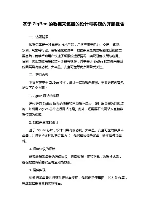
二、研究内容本文旨在基于ZigBee技术,设计一款数据采集器。
主要研究内容包括以下几个方面:1. ZigBee网络的搭建通过研究ZigBee协议的原理和网络拓扑结构,设计出合理的网络结构,并利用ZigBee芯片进行网络搭建。
此外,还需要研究网络安全和数据传输的保障。
2. 数据采集器的设计基于ZigBee芯片,设计出具有低功耗、大容量、安全可靠的数据采集器,并且支持多种数据采集方式,包括模拟信号采集、数字信号采集等。
3. 通信协议的设计研究数据采集器的通信协议,包括数据上传和下载,数据格式等,确保数据传输的安全可靠和高效率。
4. 硬件实现对数据采集器进行硬件设计与实现,包括电路原理图、PCB制作等,完成数据采集器的实物样品。
5. 软件实现基于ZigBee网络和协议,设计并实现数据采集器的控制软件,包括数据采集、数据处理、传输等。
三、预期成果1. ZigBee网络的搭建成功,并在该网络下实现数据传输和采集。
2. 开发一款基于ZigBee技术的数据采集器,并完成数据采集和处理的功能。
3. 搭建数据采集器通信协议,并能够在网络中实现高效的数据上传和下载。
4. 设计并制作数据采集器的硬件原型,并制定相应的测试方案。
5. 开发数据采集器的软件,能够对数据进行实时显示和实时监控。
四、研究方法及技术路线1. 研究ZigBee协议标准,掌握网络搭建的原理和方法。
2. 确定ZigBee网络的拓扑结构,选择合适的硬件平台和软件环境。
3. 在ZigBee网络中进行数据传输和采集实验,根据实验结果进行数据处理和分析。
自主创新研究基金本科生项目结题报告项目名称:无线数据采集系统的设计指导教师:朱健春申请人:刘琰、莫奎、王承专业班级:通信0806填写日期:2011年04月23日摘要数据采集是一项在生产、生活和科研中都会要经常进行的工作,而在一些环境、地形复杂的领域,由于有线的数据采集和传输受到了很大程度的限制,所以无线数据采集和传输就成为了人们必须要解决的一个问题。
本项目的无线数据采集系统由温度数据采集模块、无线数据收发模块和PC端软件智能控制系统三个部分组成。
可将多个测量点实测的温度数据通过无线数据收发模块发送给主节点,再由主节点通过串口通信将数据上传PC端的智能控制软件,软件系统会根据人工的设定进行温度的智能控制。
整个系统通过无线的方式进行数据收发,无需布线,不仅方便、成本低,而且解决了有线网络架设难度大的问题。
一、绪论数据采集(Data Acquisition)是获取信息的基本手段。
数据采集技术作为信息科学的一个重要分支,是以传感器、信号测量与处理、微型计算机等技术为基础而形成的--f]综合应用技术。
数据采集系统是利用计算机、通信、测控等技术采集、记录和显示现场的各种物理参量,以供管理人员和现场操作者参考的系统;是现代测控系统的基础,用于获取各种现场测量数据。
远程数据采集系统,与传统的数据采集系统相比,具有不受地理环境、气候、时间的影响等优势。
而借助无线传输手段的远程数据采集系统,更具有工程造价和人力资源成本低,传输数据不受地域的影响,可靠性高,免维护等优点。
通信、计算机等技术的飞速发展,特别是远程传输手段的多元化和技术水平的提高,使远程数据采集技术有了广泛的应用。
近年来,随着科学技术的飞速发展,尤其是通信技术、计算机技术和传感器技术的发展,特别是在传感器在信息技术领域内的广泛应用,从传感器和其它待测设备等模拟和数字被测单元中采集到的非电量或者电量信号怎样送到上位机中进行分析和处理就成为了一个难题。
传统的有线传输方式的优点在于传输的质量比较可靠,实时性比较好,但是为数据采集而架设有线网络的一次性投资较大,而且遇到一些环境、地形复杂的地方将很难架设线路。
基于ZigBee的无线数据采集系统设计与实现的开题报告一、选题背景与意义随着物联网的发展,无线传感器网络在数据采集领域逐渐得到广泛应用。
在许多应用中,如智能家居、工业自动化和农业等领域,需要使用无线传感器网络来实现数据采集、处理和控制等功能。
而ZigBee作为一种低功耗、低成本、低速率的无线通信协议,逐渐成为了物联网中常用的无线数据传输标准。
本课题旨在基于ZigBee无线协议设计与实现一种无线数据采集系统,使得该系统能够快速、准确地采集到各种环境参数数据,并将所得数据传输至数据处理端。
通过该系统,实现对数据的有效获取和实时处理,提升数据采集的效率和精度。
二、研究内容和方法本课题主要涉及以下内容:1、选定ZigBee作为通讯协议,设计无线传感器节点和集中控制节点;2、研究无线数据采集方法和协议,设计数据采集模块,并实现数据的无线传输和存储;3、研究数据处理和展示方法,实现数据的实时处理和展示。
具体方法:1、设计硬件电路和软件程序,实现传感器数据的采集、处理、无线传输和存储;2、搭建数据处理平台,实现对采集到的数据进行实时处理和展示。
三、研究预期结果本课题预期实现以下结果:1、设计出基于ZigBee无线协议的无线数据采集系统;2、实现对各种环境参数数据的实时采集和存储;3、实现数据的实时处理和展示;4、通过实验验证所设计系统的采集效率和精度,并对其进行评估。
四、研究组织和进度安排本课题的研究主要由以下步骤构成:1、文献调研和技术研究,包括Zigbee协议和无线数据采集技术的相关研究;2、硬件电路设计和软件程序开发,包括无线传感器节点、集中控制节点、数据采集模块等的设计和实现;3、数据处理平台的搭建和实现;4、实验验证和结果分析,包括对所设计系统的采集效率和精度进行评估。
预计研究时间为6个月,具体安排如下:第1-2个月:文献调研和技术研究;第3-4个月:硬件电路设计和软件程序开发;第5个月:数据处理平台搭建和实现;第6个月:实验验证和结果分析。
开题报告基于无线传感网络的数据采集系统设计1 选题的背景、意义近年来,微机电系统(MEMS)、低功耗高集成度电子器件及无线通信技术的快速发展,导致低成本、微体积、多功能的无线传感器节点设备的出现。
在未来几年内,无线传感器网络(WSN)将对人们的日常生活和几乎所有军工业领域带来巨大影响。
尤其随着无线通信和射频技术的不断发展,具有布局灵活、成本低廉、组网便捷的特点的无线数据采集系统正在逐渐取代传统的有线数据采集系统。
无线传感器网络(简称 WSN,wi r e l es s s ens or net wor ks )是综合了传感器技术、微电子技术、现代网络及无线通信技、,嵌入式计算机技术、分布式信息处理技术等各种先进现代技术,通过各类集成化微型传感器协作能够实时监测、感知和采集各种环境和监测对象的信息,并将采集到的这些信息以无线自组多跳网络方式传输到用户终端的网络技术。
WSN能以最低的成本、最大的灵活性连接任何有通讯需求的终端设备,进行数据采集和指令发送,具有一定的移动和动态调整的能力。
无线传感网络是目前信息科学领域中一个活跃的研究分支,其经历了三个阶段:智能传感器、无线智能传感器和无线传感器网络。
智能传感器是传感器中嵌入计算能力,使传感器节点不仅具有数据采集能力,且具有滤波和信息处理能力[ 1] ;无线智能传感器是在智能传感器的基础之上增加了无线通讯能力,大大延长了传感器的感知触角,降低了传感器的工程实施成本;无线传感器网络则是将网络技术引入到无线智能传感器中,使传感器不再是单个感知元件而是能够交换信息和协调控制的有机结合体,必将成为下一代互联网的重要组成部分。
无线传感器网络由大量工能相同或不同的无线传感器节点以自组织方式构成。
无线传感器节点是网络的基本单元,其体积小、成本低、具有通信能力和数据处理能力,节点的稳定运行是整个网络可靠性的基本保障【2】。
根据不同的应用目的,网络互联的传感器节点分布于监测区域中,以测量其周边环境中的光热、声音、电磁、化学成分等各种信号,从而检测到包括温度、光强度、噪声、压力、土壤成分、水质和各种移动物体的大小、速度以及移动方向等物质现象,进而在网络中完成数据处理和信息融合,最后将有用的信息数据传输给用户。
开题报告通信工程单片机的无线数据传输系统设计一、课题研究意义及现状随着通信和信息技术的不断发展,短距离无线通信技术的应用步伐不断加快,正日益走向成熟。
短距离无线通信泛指在较小的区域内(数百米)提供无线通信的技术,目前常见的技术大致有802.11系列无线局域网、蓝牙、HomeRF和红外传输技术。
无线通信技术的发展和成熟,为各种潜在的工程技术应用提供了新的通信方法和手段。
目前许多应用领域都采取无线的方式进行数据传输,这些领域涉及到小型无线网络、无线标签身份识别、非接触RF智能卡等。
与有线数据传输方式相比,无线通信的信道环境比较恶劣,可以实现的最高传输速率往往会受到很大的限制。
但无线通信也具有一些独特的优势:首先,无线通信的数据传输距离比较远(可以达到或超过RS485及CAN总线的传输距离);其次,无线通信设备在使用过程中不需要连接通信线缆,简化了工作流程,降低了设备成本。
所以尽管无线通信方式在单片机系统中应用不如其他数据传输方式广泛,还是有必要对无线数据传输方式进行介绍。
在常用的电子电路设计中,单片机是用得最多的器件。
由它制作的电子器件,具有价格低,体积小,性价比高的优势。
因此在实际电子产品的设计中,单片机得到了广泛的应用。
本课题是利用单片机实现无线数据传输,目的是通过此课题,进一步熟练使用单片机。
在设计本课题过程中,需要了解目前已有的多种实现单片机实现无线数据传输的技术,并加以提炼对比,提出改进的的技术方案,最后完成C语言编程和程序设计,并进行电路调试和测试。
本课题设计完成后,要求设计者进行多次性能测试,测试内容包括数据传输速率,数据丢失率,写出测试报告。
本文介绍了一种无线传输系统,他应用单片机和无线传输模块PTR2000,通过无线方式进行数据传输。
特别适合工业控制场合;可直接接CPU串口使用,也可以接计算机RS232接口,软件编程非常方便。
该系统使用灵活、成本低廉,可方便地嵌入到无线测控系统中。
基于无线传感器网络的数据采集系统设计的开题报告一、选题背景和意义随着科技的发展,无线传感器网络在环境监测、工业控制等领域的应用越来越广泛,成为了当前热点和前沿领域之一。
在许多应用场合中,需要采集分散在不同位置的传感器数据,以及通过传感器网络将数据传输到中心节点,进而进行存储、处理、分析和显示。
因此,基于无线传感器网络的数据采集系统设计具有重要的现实意义和深远的研究价值。
二、研究内容和目标本文将围绕基于无线传感器网络的数据采集系统设计展开研究,主要内容包括以下几个方面:1. 系统平台:选择合适的处理器、操作系统和通信协议,以确保系统具有可靠性、高效性和安全性。
2. 传感器节点:选择合适的传感器,进行数据采集和处理,并通过网络传输传感器数据到中心节点。
3. 网络协议:设计合适的网络协议,以确保数据传输的可靠性和传输效率。
4. 数据存储和处理:对传感器数据进行存储和处理,包括数据分析、数据挖掘等。
通过对以上方面的研究,旨在实现一个具有良好性能和高可靠性的基于无线传感器网络的数据采集系统,并为相关领域的研究和应用提供参考。
三、研究方法1. 文献调研:通过查阅相关文献,了解当前无线传感器网络数据采集系统已有的设计思路和方法。
2. 系统架构设计:根据文献调研和应用需求,设计基于无线传感器网络的数据采集系统的整体架构和模块划分。
3. 硬件和软件设计:根据系统架构和模块划分,选择合适的硬件平台和软件开发工具,进行系统硬件和软件的设计和实现。
4. 系统测试和评估:针对设计实现的数据采集系统,进行系统测试和性能评估,验证系统的可靠性和有效性。
四、论文结构本论文的结构分为以下几部分:第一章绪论1.1 选题背景和意义1.2 研究内容和目标1.3 研究方法1.4 论文结构第二章相关技术2.1 无线传感器网络技术2.2 数据采集系统设计原理和方法2.3 系统设计和实现的关键技术第三章系统设计与实现3.1 系统架构设计3.2 硬件和软件设计3.3 系统集成和测试第四章系统性能评估4.1 测试结果与分析4.2 系统性能评估和比较4.3 实验结果的分析和总结第五章结论5.1 研究成果和创新点5.2 研究存在的不足和改进方向5.3 应用前景及展望参考文献。
医学生命体征无线采集与分析系统的设计与实现的开题报告一、研究背景随着科技的不断发展,医学技术也在不断更新。
医学生命体征的监测和分析在临床医疗中起着至关重要的作用。
传统的监测方式是通过各种传感器采集数据,然后手动记录数据分析。
现在,无线传感器技术的发展使得医学生命体征的实时监测和分析成为可能。
医学生命体征无线采集与分析系统的设计与实现是一个热门研究课题。
二、研究内容本研究的主要内容是设计和实现一种医学生命体征无线采集与分析系统。
具体包括以下几个方面:1. 设计硬件平台。
设计采用多种传感器采集一些常见的生命体征参数,如心率、呼吸率、体温和血压等数据,并通过微控制器进行处理和数据存储。
2. 实现数据传输功能。
数据传输功能是指将采集到的数据通过无线传输方式传输到远程终端或云端平台,以便医生或护士实时监测患者的生命体征。
3. 数据分析功能。
主要是对采集到的生命体征数据进行分析和处理,为实时监测提供准确的参考。
三、研究意义本研究设计和实现的医学生命体征无线采集与分析系统有如下意义:1. 提高临床医疗水平。
医学生命体征无线采集与分析系统可以提高医生和护士的工作效率,并且实时监测患者的生命体征可以大大减少医生和护士出现疏忽的可能。
2. 降低医疗成本。
将医学生命体征无线采集与分析系统应用到临床中,可以降低医疗成本,因为该系统可以减少患者的住院时间和频繁检查的次数。
3. 促进医疗技术的发展。
设计和实现医学生命体征无线采集与分析系统可以促进医疗技术的发展,在医疗工作中更加普及无线生命体征监测技术。
四、研究方法本研究主要采用以下方法:1. 硬件设计。
根据医学生命体征的特点和实际需求,设计多种传感器采集数据,并利用微控制器进行数据处理和存储。
2. 软件开发。
利用一些开源的软件工具,如Arduino和Python等,编写程序,实现医学生命体征无线采集与分析系统的数据传输和分析功能。
五、研究预期结果通过本研究,将设计和实现一种医学生命体征无线采集与分析系统。