Brookfield博勒飞DV3T 流变仪产品说明书
- 格式:pdf
- 大小:424.03 KB
- 文档页数:2
博勒飞DV-ⅢUltra流变仪产品简介美国Brookfield其中博勒飞DV-ⅢUltra流变仪可使用RheoCalc软件(标配)通过PC进行参数设置与全程测量控制,高精度流变仪,按键标示明确,程序化设计,操作简便。
主要特点DV-ⅢUltra高精度流变仪,按键标示明确,程序化设计,操作简便;可使用RheoCalc软件(标配)通过PC进行参数设置与全程测量控制;通过剪切率可分析材料的流动性、蠕变、屈服应力、流变曲线(混合、泵送、喷涂)流平和恢复等特性指标;可单机编程:输入数据,指定温度,开始运行程序,在内置显示屏上浏览结果;2600种转速,可用于很宽范围的流变分析;整机包括:主机,转子一套,RheoLoader软件,RHEOCALC32中文软件,EZ-Yield软件,RTD温度探针,支架和底座,保护腿,包装箱;精确度:±1.0%(满量程), 重现性±0.2%;单机模式操作时也可以使用内建的数学模型进行数据处理和分析;雨泽仪器推荐各科研单位使用的研究级流变仪。
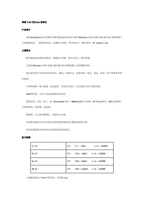
技术参数LV DVⅢ+:+1*-2McP, 0.01-250RPMRV DVⅢ+:+100-40McP, 0.01-250RPMHA DVⅢ+:+200-80McP, 0.01-250RPMHB DVⅢ+:+800-320McP,0.01-250RPM *测量粘度低于15cP的样品时,需加配ULA博勒飞R/S Plus 流变仪产品简介博勒飞R/S Plus 流变仪可进行控制剪切率/剪切应力的流变测试。
R/S Plus 流变仪代表着博勒飞推荐给客户的最好选择—同时具有控制剪切率和剪切应力两种模式的流变仪,与同类型的流变仪相比,博勒飞R/S Plus 流变仪具有更多的选择性和灵活性,并升级了测试和控制性能的编码能力,同时仍可进行完美的流变分析,这些都是建立在可以承受的价格之上的,针对不同的样品,R/S Plus 有三种不同配置,都具有坚固的设计,可以长期无故障使用,快速的转子链接和溶液清洗的表面可以为客户节约大量的时间和金钱。
美国BROOKFIELD , VT旋转粘度计Brookfield(博力菲) LVT型旋转粘度计操作规程LVT 型属于指针式旋转粘度计(低粘),其使用范围为:80cP~2,000,000cP(厘泊),配备4支转子,有8种转速可供选择,共可分为32个测量范围。
此外,粘度计另配有小样品测量系统,所需样品量约7ml,测量范围为5 cP~9000cP,配备1支转子和一个不锈钢样品池,另配有恒温池(外接循环水域)。
操作规程:1.将仪器安装好后置于稳定的台面之上,并通过旋转底部的三个螺脚,使顶端之水平仪中的气泡居于中央,仪器的水平调节完毕.接通电源(220V 50HZ)。
2.选择安装转子, 提住连接件顶端,转子左旋上紧.如使用小样品测量系统,则首先依次将小样品平板支架,恒温池,样品池及转子安装至仪器上。
3.选择所需转速(从低速开始选择,避免指针偏转过大造成损坏),打开马达开关,仪器即开始测量,表盘显示的数值即为样品扭矩值AB,在样品稳定时大约30S钟后读数.4.查表找出所选转子与转速对应的系数Y,则可得出所测的CP粘度值=AB×Y 厘泊.5.若需改变转速,则直接调旋钮键,无需关闭马达。
若更换转子,则必须将马达关闭,再进行更换,然后按前述方法查表找出所选转子与转速对应的系数Y。
6.测量完毕后, 应及时将马达关闭, 将转子取下, 清洗干净拭干后放回盒内.注意事项及说明:1.对于该类型粘度计(小样品测量系统除外), 每一组确定的转子与转速对应一确定的测量量程, 也就是说, 4支转子, 配上8种转速, 共有4 18=32量程.转子体积越小(编号越大), 转速越低,所对应的量程越大。
反之则越小. 在实际测量过程中, 若样品的粘度大于当前量程, 此时则需将转速减低, 或选择一个体积更小的转子, 直至能够测量.2.需要指出的是, 度盘上表示的是测量的扭矩值占当前满量程值的百分比. 生产商在仪器出厂时规定当该值介于10%-90%时, 即可读数,否则无效. 如能将此值调至40-80%时再读数则为最佳. 其方法如下, 当百分比低于40%时, 则说明当前量程过大, 此时增大转速或更换一个体积更大的转子, 百分比将增大, 直至所需. 反之, 若超过80%, 则降低转速,或更换一个体积更小的转子,百分比将减小,直至所需. 此时即可读取度盘上的扭矩值.3.应尽量避免仪器长时间高速旋转(比如100转/分钟),可通过更换转子以达到改变量程的目的, 也就是说,虽然用体积大的转子(小号转子)在低速度下的组合和使用体积小的转子与高速度的组合可以得到相同的测定范围, 但为了避免高速度产生涡流而使测定结果不稳定同时减少仪器的磨损, 应尽量选择小号转子与低速度的组合,这是一个重要的原则.4.在更换转子时, 应注意先用一只手将连接部上端固定住, 再旋上或旋下转子.5.对于转子要小心使用, 不要弄脏, 碰弯偏心, 并避免刮擦表面.1。
第1篇一、概述流变仪是一种用于测量材料流动性能的仪器,广泛应用于材料科学、生物医学、食品工业等领域。
为确保流变仪的正常运行和操作人员的安全,特制定本操作规程。
二、操作前的准备1. 检查流变仪外观,确保无损坏,各部件连接牢固。
2. 检查流变仪的电源线和压缩空气管路,确保无破损、老化现象。
3. 检查仪器内部各部件,如传感器、测量头、转子等,确保其清洁、无异物。
4. 根据实验要求,准备好待测样品。
三、操作步骤1. 开机(1)连接总电源,打开插板中标记着“流变仪”、“显示器”和“电脑”的电源。
(2)打开空气压缩机,待空气压力升至标准值(左边的气压表不低于5bar)后,打开空气阀。
(3)打开电脑和流变仪主机电源,自检结束,确认主机处于正常状态。
2. 设置参数(1)在电脑上打开流变仪软件,进入控制面板。
(2)根据实验要求,设置测试参数,如温度、频率、应变等。
3. 测试样品(1)将样品放入流变仪测量头,确保样品表面平整。
(2)启动测试程序,开始测试。
4. 数据处理与分析(1)测试结束后,查看测试结果,如流变曲线、剪切应力等。
(2)根据实验要求,对数据进行处理和分析。
四、操作注意事项1. 操作过程中,确保仪器电源线和压缩空气管路连接牢固,防止漏电、漏气。
2. 操作人员应佩戴安全眼镜,以防样品飞溅。
3. 手上有水或油污时,不得操作仪器。
4. 非专业人员不得自行拆卸仪器和修理。
5. 空压气压力不得大于4bar,否则可能损坏空气轴承。
6. 确保EHEIM水浴软管连接正确紧密,并畅通。
五、操作后的维护1. 关闭流变仪主机和电脑电源。
2. 关闭空气压缩机。
3. 清洁仪器表面,保持仪器清洁。
4. 定期检查仪器各部件,确保其正常工作。
5. 按照仪器说明书进行定期保养。
六、安全注意事项1. 操作人员应熟悉流变仪的操作规程,了解仪器的安全性能。
2. 严格遵守操作规程,确保操作安全。
3. 发生异常情况时,立即停止操作,切断电源,报告相关人员。

美国BROOKFIELD博勒飞THERMOSEL加热器操作手册手册编号:M94-204-I0612说明:请以英文操作手册为准,中文版本仅供参考。
BROOKFIELD ENGINEERING LABORATORIES, INC.11 Commerce Boulevard, Middleboro, MA 02346-1031 USAT EL 800-628-8139 or 508-946-6200 F AX 508-946-6262 (English) (Chinese)I.简介-----------------------------------------------------------------------------------------------------------3I.1使用------------------------------------------------------------------------------------------------------------31.2规格-----------------------------------------------------------------------------------------------------------3I.3安全标志和预防措施----------------------------------------------------------------------------------------3 I.4操作说明-------------------------------------------------------------------------------------------------------4 I.5 综述------------------------------------------------------------------------------------------------------------6 I.6粘度测量------------------------------------------------------------------------------------------------------7 I.7清洁----------------------------------------------------------------------------------------------------------10附录A粘度范围/转子参数------------------------------------------------------------------------------------11 附录B高温型硅油标准液------------------------------------------------------------------------------------15 附录C一次性样品杯-----------------------------------------------------------------------------------------16 附录D转子的选择--------------------------------------------------------------------------------------------18 附录E温度换算表:摄氏度和华氏度-----------------------------------------------------------------------19 附录F在线帮助和额外资源----------------------------------------------------------------------------------20 附录G保修和售后服务----------------------------------------------------------------------------------------21BROOKFIELD Thermosel 系统是配合BROOKFIELD 粘度计或流变仪在高温条件下准确测量液体粘度值的一个附件。

美国BROOKFIELD博勒飞DV2T粘度计操作手册手册编号:M13-167说明:请以英文操作手册为准,中文版本仅供参考。
目录I.简介-----------------------------------------------------------------------------------------------------------4I.1仪器组件------------------------------------------------------------------------------------------------------51.2规格-----------------------------------------------------------------------------------------------------------7I.3技术指标-------------------------------------------------------------------------------------------------------8 I.4安装方法------------------------------------------------------------------------------------------------------9 I.5安全标志和警告---------------------------------------------------------------------------------------------10 I.6控制面板介绍----------------------------------------------------------------------------------------------11 I.7仪器清洁----------------------------------------------------------------------------------------------------11 II. 入门指南---------------------------------------------------------------------------------------------------13 II.1接通电源------------------------------------------------------------------------------------------------------------13 II.2 自动调零-----------------------------------------------------------------------------------------------------------13 II.3 状态栏--------------------------------------------------------------------------------------------------------------14 II.4 仪器导向按钮----------------------------------------------------------------------------------------------------15 II.5 主屏幕--------------------------------------------------------------------------------------------------------------16 II.5.1粘度测试设置-----------------------------------------------------------------------------------------------16 II.5.2加载测试------------------------------------------------------------------------------------------------------19 II.5.3查看结果------------------------------------------------------------------------------------------------------20 II.5.4文件管理------------------------------------------------------------------------------------------------------20 II.5.5外部控制模式----------------------------------------------------------------------------------------------- 20 II.6测量范围------------------------------------------------------------------------------------------------------------20 II.7超出测量范围-------------------------------------------------------------------------------------------------------21 II.8打印-------------------------------------------------------------------------------------------------------------------22 III粘度测试操作---------------------------------------------------------------------------------------------25 III.1快速入门-----------------------------------------------------------------------------------------------------------25 III.2 测试前的准备---------------------------------------------------------------------------------------------------25 III.3 转子/速度的选择-----------------------------------------------------------------------------------------------26 III.4多个数据点--------------------------------------------------------------------------------------------------------28 III.5数据采集的选择-------------------------------------------------------------------------------------------------29 III.6结束条件-----------------------------------------------------------------------------------------------------------31 III.7附加测试参数----------------------------------------------------------------------------------------------------32 III.8运行测试-----------------------------------------------------------------------------------------------------------35 III.9 结果----------------------------------------------------------------------------------------------------------------38 III.10数据平均---------------------------------------------------------------------------------------------------------40 IV 设置---------------------------------------------------------------------------------------------------------43 IV.1设备设置-----------------------------------------------------------------------------------------------------------43 IV.2用户设置-----------------------------------------------------------------------------------------------------------47 IV.3全程设置-----------------------------------------------------------------------------------------------------------48 IV.4管理功能--------------------------------------------------------------------------------------------------53 IV.4.1登录和锁定---------------------------------------------------------------------------------------------------53IV.4.2用户和权限---------------------------------------------------------------------------------------------------54 IV.4.3设置时间和日期---------------------------------------------------------------------------------------------56 IV.4.4备份和导入---------------------------------------------------------------------------------------------------56 IV.4.5默认路径-------------------------------------------------------------------------------------------------------57 IV.4.6设置重置-------------------------------------------------------------------------------------------------------57 IV.4.7设备重置-------------------------------------------------------------------------------------------------------57 IV.4.8校准提醒-------------------------------------------------------------------------------------------------------58 IV.4.9保存账号记录------------------------------------------------------------------------------------------------59 V PG flash软件-----------------------------------------------------------------------------------------------60附录A 安装锥板型粘度计------------------------------------------------------------------------------------64 附录B粘度范围-----------------------------------------------------------------------------------------------68 附录C粘度测量的变量-------------------------------------------------------------------------------------73 附录D转子和机型编号--------------------------------------------------------------------------------------75 附录E校准程序-----------------------------------------------------------------------------------------------78 附录F护腿-----------------------------------------------------------------------------------------------------85 附录G转速的选择--------------------------------------------------------------------------------------------87 附录H实验室支架--------------------------------------------------------------------------------------------88 附录I DVE-50A探针夹--------------------------------------------------------------------------------------91 附录J故障诊断和排除---------------------------------------------------------------------------------------93 附录K仪器尺寸图--------------------------------------------------------------------------------------------95I.简介自从1985年面世以来,博勒飞DV-II系列粘度计一直处于工业粘度计的领先地位。

美国BROOKFIELD粘度计DV-II+型操作说明美国BROOKFIELD公司感谢各位使用BROOKFIELD黏度计。
该操作说明只是一份简单使用说明,详细内容请参照英文说明书。
I.仪器配置:1)DV-II+黏度计2)A型支架3)成套转子4)电源线5)RTD温度电极6)保护腿7)装运箱8) DVLOADER软盘(3-1/2′)8)联接电缆9)说明书请检查您的仪器装置,若有缺损,请向当地代理商索取。
II.安装1.如图所示安装好黏度计支架。
2.将黏度计支承柄插入支架的夹套中,并锁紧夹套螺丝,运转齿轮螺丝可调节黏度计上下位置。
3.连接RTD温度电极至DV-II+后部接口。
4.调节黏度计底座的三个水平螺丝,直至顶部的水泡在中央位置。
5.确定DV-II+的电源开关置于OFF状态,接通电源。
(DV-II+黏度计必须接地)6.使用前须打开电源开关ON预热10分钟。
7.如需要,通过电缆线将DV-II+及电脑相连接。
III.各键功能1.↑键:用于增加转速(SPEED)或转子代号(SPINDLE)或菜单目录(OPTIONMENU)。
2.↓键:用于减小转速(SPEED)或转子代号(SPINDLE)或菜单目录(OPTIONMENU)。
3.MOTOR ON/OFF/ESCAPE键:用于开始或停止马达运行,ESCAPE用于退出选择菜单。
4.SET SPEED键:该键只有在马达ON状态下才能工作,使黏度计在当前转速下开始转动。
也可用于选择定制转速。
5.SELECT DISPLAY键:选择显示以下参数,CP黏度值(cP或mPa.s)SS剪切应力(dynes/cm2或Newtons/m2)SR剪切率(1/sec)6.ENTER/AUTO RANGE键:ENTER键:用于执行当前菜单。
AUTO RANGE键:按此键可得知所选用转子在当前转速下可测的最大黏度值。
7.SELECT SPINDLE键:按第一下时开始选择转子代号,按第二下是确定当前选好的转子数。
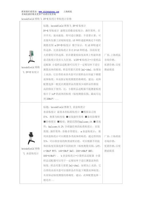
brookfield 博勒飞 DV-E 粘度计和粘度计价格brookfield 博勒飞 DV-E 粘度计 标题:brookfield 博勒飞 DV-E 粘度计DV-E 型粘度计 最便宜的数显粘度计,操作简单,打开开关,旋动旋钮,即可进行测量,不需要计算,可直接从仪器上读取粘度值。
18种转速能够满足不同的测量范围 a)DV-E+粘度计 数字显示,有18种转速可供选择,比表盘粘度计多出8-10种转速,因而有更大的量程可供选择,但在测量低粘度流体上性能和表盘式粘度计没有太大区别。
b)DV-E 粘度计+小量样品适配器 小量样品适配器可以用于一定剪切率下进行测量流体的粘度,样品用量只需要2ml-16ml 。
如果加上水浴,它自带的水浴夹套可以使样品在恒温下测量流体粘度,从而保证粘度测量的准确度。
建议:此种配置选择一般是在测量样品用量很少或样品价格很高的情况下使用。
注:小量样品适配器不能测量粘度值小于1cP 的流体的粘度(粘度测量范围:最高可达到20McP )...厂家:上海政泓 市场价格: 优惠价格:百度搜索联系brookfield 博勒飞 表盘粘度计 标题:brookfield 博勒飞 表盘粘度计表盘粘度计 最基本的标准粘度计 ■模拟显示扭距%,换算为粘度值 ■安装操作简单 ■备有防爆型 ■价格便宜 ■精度:测量范围的±1% ■重现性:±0.2% 全球最经典的标准粘度计,安装简便,操作简单,价格非常便宜。
a 表盘粘度计: 使用表盘粘度计可以测量各类流体的粘度,通过得到扭矩%,可以很容易的换算成厘泊值。
可以根据不同流体的粘度范围选择不同的机型(粘度测量范围:LVT :1-2McP RVT :100-8McP HAT :200-16McP HBT :800-64McP )。
b 表盘粘度计+小量样品适配器 小量样品适配器可以用于一定剪切率下进行测量流体的粘度,样品用量只需要2ml-16ml 。

险危谨防触电、火灾或者烫伤z 仅可让掌握并理解本手册内容的专业人员对转矩流变仪进行检修与使用z 设备使用者对设备进行接通电源时应遵循所有现行相关规定z 仪器内部诸多部件均使用电网电压工作,请不要触摸。
不得在通电情况下触摸没有保护措施的零件或者螺丝端子z 请安装好所有接线端子,并在通电前确保没有线或端子裸露在外 z 在开启传动前请确认温度是否稳定、各个部位连接是否正确,然后再启动电机z 对设备进行检修之前: 断开总电源连接。
在开关上挂上“请勿合闸”标志并采取措施防止其他人接通电源。
等候6分钟(伺服驱动器DC 总线电源放电)。
重新上电,测量三相电压是否为正确(相电压380V ,线电压220V ),各仪表工作状态指示灯是否正常。
若不遵守规定,将会导致死亡或严重伤害。
目录1 概述 (1)1.1转矩流变仪的应用 (1)1.2 RM-200系列转矩流变仪具有如下特点: (1)2 系统组成与性能指标 (3)2.1 RM200C型转矩流变仪认知 (4)2.1.1 主机外貌 (4)2.1.2 混炼器平台 (5)2.1.3 挤出机平台 (6)2.2 性能指标 (7)3 机械安装 (8)3.1 主机固定 (8)3.2 安装混合器平台 (8)3.3 安装挤出机平台 (9)4 电气安装 (10)4.1 电源接入 (10)4.2 通讯电缆连接 (10)5 相关软件安装 (11)5.1 控制软件以及各应用软件安装 (11)5.1.1 安装控制软件 (11)5.1.2 安装数据处理软件 (13)6 实验操作 (14)6.1 混炼器实验 (14)6.1.1 实验准备 (14)6.2 挤出机实验 (15)7 实验数据处理 (16)7.1 交联实验 (16)7.2 融合实验 (17)7.3 热稳定性实验 (18)7.4 叠加实验 (19)7.5 差异显著性分析 (20)7.6 挤出机实验报告 (21)7.7 熔体粘度分析 (22)8 维修与保养与常见问题解答 (23)9 电气连接配线图 (24)1概述橡塑材料在加工成型的过程中,几乎都要涉及其流动性。

美国BROOKFIELD 博力飞DV-II+可编程控制式粘度计
操作说明
1. 仪器原理 DV-II+型粘度计测定相当广范围的液体粘度,粘度范围与转子的大小和形状以及转速的有关。
因为对应于一个特定的转子,在流体中转动而产生的扭转力一定的情况下,流体的实际粘度于转子的转速成反比,而剪切应力与转子的形状和大小均有关系。
对于一个粘度已知的液体,弹簧的扭转角会随着转子转动的速度和转子几何尺寸的增加而增加,所以在测定低粘度液体时,使用大体积的转子和高转速组合,相反,测定高粘度的液体时,则用细小转子和低转速组合。
2. 控制面板介绍
2.1 UP ARROW:上箭头,用于选择转速,转子,以及其他选项。
2.2 DOWN ARROW:下箭头,用于选择转速,转子,以及其他选项。
2.3 MOTOR ON/OFF ESCAPE:开关电机,或退出选项菜单。
2.4 SET SPEED:转速设定。
2.5 SELECT DISPLAY:选择所需显示的参数:粘度cP,剪应力SS,剪切率SR。
2.6 ENTER /AUTO RANGE :确认选中的选项,或显示当前转子/转速组合下,可测量的粘度最大值。
2.7 SELECT SPINDLE:按第一下进入转子设定模式,通过上下箭头键选择合适的转子编号,再按第二下确定。
2.8 PRINT:进入或退出打印模式。
2.9 OPTION/TAB OPTION:开启选项菜单。
TAB:在可选参数之间切换。
数字流变仪DV-III+操作指南手册编号M/98-211请记录你的黏度计的型号及编号。
有了这个信息可以帮助我们快速地解决有关你的仪器的任何问题。
型号:编号:BROOKFIELD 工程实验室公司11 Commerce Boulevard,Middleboro,MA 02346-1031 USAI.介绍BROOKFIELD DV-III+可编程流变仪可以测量流体在给定剪切转速下的剪切力及黏度。
黏度是测量流体对流动阻力的指标。
你将在BROOKFIELD的出版物‘MORE SOLUTIONS STICKY PROBLEMS’中找到有关黏度理论的详细介绍,你的DV-III+就包含在这本书中。
DV-III+流变仪具有同DV-III一样操作特性:精确和简便。
同样符合BROOKFIELD测量方法,理论上增加了程序的可编性,键盘,菜单和计算机软件。
DV-III+的操作原理是通过一个标准游丝来转动一个转子(浸在被测液体里),测量出流体对转子的阻力,通过旋转的转换器测出游丝扭力。
决定DV-III+的测量范围的因素是:转子的转速,转子的形状及尺寸,转子所在的容器,标准游丝的力矩范围。
BROOKFIELD提供四组游丝力矩:型号弹簧力矩达因/厘米千分之一(毫米)牛顿/米LVDV-III+ 673.7 0.0673RVDV-III+ 7187.0 0.7187HADV-III+ 14374.0 1.4374HBDV-III+ 57496.0 5.7496力矩标准越高,测量范围越高,每一力矩标准的测量范围可以在附录B中找到。
所有测量单位都标注在CGS或SI方法中。
1在DV-III+流变仪上,黏度显示单位为厘泊符号:CP 或毫帕/秒符号:mpa.s2剪切力的单位为D/CM2或N/M23剪切速率的单位为1/sec4力矩单位在DV-流变仪上显示为达因/厘米或牛顿/米S1系统测量单位的等价计算公式为:S2 CGS黏度 1mpa.s = 1cp剪切力 1牛顿/平方米=10达因/CM2力矩 1牛顿/米=107达因/厘米本手册黏度是适合CGS单位I.1 备件对于Cone/plate型:一个转子扳手,一个圆锥转子和样品杯。
美国BROOKFIELD博勒飞DV-S粘度计操作手册手册编号No.:CM12-354SPECIALISTS IN THEMEASUREMENT ANDCONTROL OF VISCOSITY BROOKFIELD ENGINEERING LABORATORIES, INC.11 Commerce Boulevard, Middleboro, MA 02346-1031 USAT EL 800-628-8139 or 508-946-6200 F AX 508-946-6262 (English) (Chinese)I. 简介------------------------------------------------------------------------------------------------------------3I.1 仪器组成----------------------------------------------------------------------------------------------------3 I.2 规格----------------------------------------------------------------------------------------------------------4 I.3 技术指标----------------------------------------------------------------------------------------------------4 I.4 安装方法----------------------------------------------------------------------------------------------------5 I.5 安全标志和警告-------------------------------------------------------------------------------------------5 I.6 控制面板介绍----------------------------------------------------------------------------------------------5 I.7 仪器清洗----------------------------------------------------------------------------------------------------6II. 操作说明-----------------------------------------------------------------------------------------------------7II.1 接通电源---------------------------------------------------------------------------------------------------7 II.2 选择转子---------------------------------------------------------------------------------------------------7 II.3 转速的选择和设定---------------------------------------------------------------------------------------8 II.4 自动显示量程以及CGS和SI单位制的选择------------------------------------------------------9 II.5 超出测量范围--------------------------------------------------------------------------------------------10 II.6 粘度测量--------------------------------------------------------------------------------------------------10附录A –粘度范围-------------------------------------------------------------------------------------------12 附录B –粘度测量中的变量-------------------------------------------------------------------------------15 附录C –转子和机型代号----------------------------------------------------------------------------------17 附录D –校验方法-------------------------------------------------------------------------------------------19 附录E – A型实验室用粘度计安装支架-----------------------------------------------------------------24 附录F –故障诊断和疑难解答----------------------------------------------------------------------------26 附录G –保修和售后服务----------------------------------------------------------------------------------27DV-S是美国Brookfield博勒飞公司粘度计系列中的实验室仪器,它可以与Brookfield博勒飞产品系列的其它附件如超低粘度适配器、小量样品适配器、升降支架、螺旋适配器、恒温循环水浴或加热器附件等一起使用,从而构成适应范围宽广而全面的粘度测量系统。
F L E X 3I n s t r u c t i o n m a n u a lINDEX:1.PRELIMINARY AND SAFETY (3)1.1.P RELIMINARY INSTRUCTION (3)1.2.D URING USE (3)2.INSTRUMENT DESCRIPTION (4)2.1.I NTRODUCTION (4)2.2.T RANSDUCER’S FUNCTIONS (4)3.POWER SUPPLY (5)4.HINTS FOR FLEXIBLE CLAMPS USE (5)5.INSTALLATION (5)6.MAINTENANCE (6)7.SPECIFICATIONS (7)7.1.E UROPEAN DIRECTIVES (7)7.2.S AFETY S TANDARDS (7)7.3.E LECTRICAL FEATURES (7)7.4.M EASURING HEAD MECHANICAL FEATURES (7)7.5.E NVIRONMENT (7)8.SERVICE (8)8.1.W ARRANTY C ONDITIONS (8)8.2.S ERVICE (8)1. PRELIMINARY AND SAFETY1.1. Preliminary instruction∙ Read this instruction m anual and the instrument’s one before starting use.∙ Any instruction preceded by the caution symbol must be observed in order to avoidaccidents or damages.∙ This product must be used only by qualified personnel practicing applicablesafety precautions, wear protective clothing and gloves as required.∙ Do not effect any measurement under conditions beyond the limits specified in thismanual.∙ Always connect electronics unit to display device before installing the flexiblemeasuring head.∙ Do not install the clamp around cables where the current flowing is greater thanthe maximum measurable current (overrange).The FLEX3 transducer and interconnection cable use double insulation to protect the operator from possible hazardous potentials of the bus. Make sure the electronics package is well away from the bus. The current probe is rated for Installation Category III, Pollution Degree 2. The maximum voltage to earth rating for the transducer and cable is 1000V AC .1.2. During use∙ Always de-energize circuit under test before installing flexible measuring head. Alwaysinspect the connecting cable and flexible measuring head for damage before using this product.∙ Do not use product if damaged.∙ Do not use the clamp on non-insulated conductors whose potential to earth exceeds1000V and for frequencies over 5kHz.∙ Do not use the clamp outdoor.∙ Do not use the clamp at altitudes exceeding 2000 meters.∙ Do not expose the clamp to water splashes.∙ Keep the clamp gap perfectly clean.2. INSTRUMENT DESCRIPTION2.1. IntroductionDear Customer, we thank you for your patronage. The instrument you have just purchased will grant you accurate and reliable measurements provided that it is used according to the present manual’s instructions.FLEX3 is an innovative current transducer that combines easy use with measurement accuracy.The FLEX3 current probe is similar in purpose to current transformer used to measure phase currents. The output is voltage signal proportional to the derivate of AC current in the conductor. The output signal is available via a 3 pin connector (see picture 2 for output signal pin assignment).Pin 1 + OutputPin 2 - OutputPin 3 ShieldPicture 12.2. Transducer’s functionsThe transducer is a versatile current probe that may be wrapped around most conductors. The transducer has a preset bend that allows the transducer to be more easily maneuvered around the conductors (see picture 2 for FLEX3 head transducer). It's application versatility and isolation rating clearly distinguish the FLEX3 transducer from other current measuring methods. The measuring transducer is constructed from non-ferrous materials, minimizing any circuit loading due to magnetic influence.The frequency response of the current probe is rather wide compared to conventional CTs. This allows the user to monitor a much wider range of line harmonic components than conventional CTs allow. The FLEX3 transducer was designed to be very flexible, larger in aperture and smaller in cross section than many conventional CTs. This allows measurements in tight places as never before possible.3. POWER SUPPLY The FLEX3 is a passive transducer and does not require any power supply.4. HINTS FOR FLEXIBLE CLAMPS USE All flexible clamps are based on Rogowski's coil principle:dt di M V coil -= which shows that the voltage output signal is proportional to the rate of change of current.In order to get current value, the voltage output signal is integrated electronically.Typically the voltage output signal is really low and this suggests using shielded cable for coil connection to instrument's inputs.5. INSTALLATIONThe current probe was designed to allow the operator to connect this measurement device around a conductor without disconnecting the conductor, as many CTs presently require. Even though the current probe output is AC, there are instances where the user will want to orient the transducer so that proper polarity will exist at the output terminals. This is done by installing the transducer around the conductor with the molded-in arrow on the latch (see picture 2) pointing in the direction of conventional current flow. Conventional current flow is defined as current flowing from the generator to the load.The current probe must be installed with the interconnection cable on the outside of the loop when the latch is engaged. The polarity arrow, the double insulation, and the warning symbols will all be on the outside of the loop. It should also be noted that the current probe would produce twice the output voltage if you wrap the transducer around the conductor twice.There is minimal shock hazard using a FLEX3 current probe. Each transducer has been Hi-Pot tested to several thousand volts with no voltage breakdown. Thisparticular characteristic allows high-current measurement (with a wide frequency bandwidth) of conductors at less than 1000V AC potential to earth.Do not exceed the minimum bending radius of the FLEX3 current transducer when installing the transducers around the conductors. Exceeding the bending radius will degrade the measurement accuracy.6. MAINTENANCEMake sure the current probe and the output cables are clean before installing them around the conductors. If the transducers and cables are not clean, the contaminants on them may provide a conductive path for a high-voltage breakdown. Also, check the transducer and output cables for cuts and abrasions. The transducer should not be used if damaged.Preventive maintenance primarily consists ofcleaning the transducers and cables toprevent surface contamination. Use a mild detergent and water to clean the transducers and cables. Remove the detergent with clean water, then wipe dry with a clean cloth.7. SPECIFICATIONS7.1. European directivesThis instrument has been designed in compliance with the EMC standards in force and its compatibility has been tested for EN50081-1 (class B) and EN50082-2.This instrument complies with the prescriptions of the European directive on low voltage 73/23/CEE (LVD) and EMC directive 89/336/EEC, amended by 93/68/EEC.7.2. Safety StandardsStandard: EN61010-1, EN61010-2-032Insulation: Double insulationPollution: 2Working category: CAT III, 1000 V AC RMS Phase - Earth7.3. Electrical featuresCurrent Range: 3000A AC RMSOutput Sensitivity (on 10kΩ): 39.1uV/AAccuracy (at +25°C): ± 1.5% of reading (45 - 65Hz)Frequency Range: from 10 Hz to 5kHz (-3dB)Phase Error: < ± 1° (Output on 10kΩ≥ 2mV, 45 - 65 Hz)< ± 3° (Output on 10kΩ < 2mV, 45 - 65 Hz) Position Sensitivity: ± 2 % of range conductor close to coil± 4 % of range close to coil fastener7.4. Measuring head mechanical featuresLength of transducer: 0.60mMaximum conductor diameter: approx. 7" (180 mm)Bend radius: 38mmOutput Connection: approx. 2.0m cable with 3 way connector Weight: 215 g7.5. EnvironmentOperating Temperature: from -20°C to +60°CStorage Temperature: from -40°C to +80°COperating and storage humidity: from R H 15 % to R H 85 %8. SERVICE8.1. Warranty ConditionsThis instrument is guaranteed against any defect in material and manufacturing in compliance with the general sales terms and conditions. Throughout the period of guarantee all defective parts may be replaced and the manufacturer reserves the right to repair or replace the product.If the instrument is to be returned to the after-sales service or to a dealer, transportation costs are on the customer’s behalf. Shipment method however shall be agreed upon.A report must always be enclosed to a rejected product stating the reasons of its return. To ship the instrument use only the original packaging material; any damage that may be due to no-original packing shall be charged to the customer.The manufacturer declines any responsibility for damages caused to persons and/or objects.Warranty is not applied in the following cases:∙Any repair that might be necessary, as a consequence of a misuse of the instrument or of its use with non compatible devices.∙Any repair that might be necessary as a consequence of improper packaging.∙Any repair that might be necessary as a consequence of service actions carried out by unauthorized personnel.∙Any modification of the instrument carried out without the authorization of the manufacturer.∙Use not provided for in the instrument’s specifications or in the instruction manual.The content of this manual cannot be reproduced in any form whatsoever without prior authorization of the manufacturer.NOTE All our products are patented and their trade marks registered. The manufacturer reserves the right to modify the product specificationsand prices if this is aimed at technological improvements8.2. ServiceIf the instrument does not operate properly, before contacting the after-sales service check cables as well as test leads and replace them if necessary.Should the instrument still operate improperly check that the operation procedure is correct and conforms with the instructions given in this manual.If the instrument is to be returned to the after-sales service or to a dealer transportation costs are on the customer’s behalf. Shipment shall be however agreed upon.A report must always be enclosed to a rejected product stating the reasons of its return. To ship the instrument use only the original packaging material; any damage that may be due to no-original packing shall be charged to the customer.Miramar, FLPhone: 954-499-5400 Fax: 954-499-5454 。