第九章 光学系统的像质评价(2013第15讲)分解
- 格式:ppt
- 大小:1.66 MB
- 文档页数:27

第九章光学系统的像质评价分解光学系统的像质评价是对光学系统成像性能的定量分析和评估。
在光学系统设计和制造中,评价光学系统的像质是非常重要的,可以帮助工程师了解光学系统的成像性能,指导设计优化和制造流程改进。
本文将对光学系统的像质评价进行分解。
首先,光学系统的像质评价包括像散、相对孔径、像场曲率、像场曲率和像场畸变五个方面。
像散是光学系统成像时,由于透镜折射作用,会导致不同波长的光线成像位置不同,从而引起色差。
相对孔径指的是光学系统的数值孔径,是透镜或物镜口径与焦距之比,决定了光线的收集能力和分辨能力。
像场曲率是光学系统成像平面与对象平面之间的位置关系,如果成像平面与对象平面不在同一个位置,就会导致像场曲率,影响成像质量。
像场畸变是指光线通过透镜组成像时,由于透镜非理想的成像性能,使得成像出现畸变,影响成像准确性。
其次,光学系统的像质评价还包括分辨力、像点扩散函数(PSF)和耦合。
分辨力是指光学系统能够分辨的最小物体细节大小,它与光学系统的焦距和数值孔径有关。
像点扩散函数是用来描述光学系统成像效果的函数,它描述了光线通过光学系统后,成像点的形状和分布。
耦合是指光学系统中不同光线之间相互作用和干涉的现象,会导致成像时出现噪声和其他不确定性因素,影响像质。
最后,光学系统的像质评价还包括像偏、像移和畸变。
像偏是指光学系统成像时,成像点相对于理想位置的偏移,可以通过调整光学元件的位置和参数来进行校正。
像移是指光学系统成像时,成像点相对于成像平面的位置偏移,可以通过调整焦距和收集角度来进行校正。
畸变是指光学系统成像时,成像点位置相对于对象点位置的非线性偏差,分为径向畸变和切向畸变两种,可以通过调整透镜组参数和改变光路来进行校正。
综上所述,光学系统的像质评价是一个多方面的指标体系,涉及到像散、相对孔径、像场曲率、像场曲率和像场畸变等多个方面。
对于光学系统设计和制造来说,一个好的像质评价指标体系可以帮助工程师评估和优化光学系统的成像性能,提高光学系统的质量和效率。

光学系统像质评价方法那最直观的一种呢,就是星点检验法。
这就像是拿个小镜子去照星星,看星星在镜子里的成像情况。
如果成像清晰,像个完美的小亮点,那就说明这个光学系统还不错呢。
要是星星的像看起来模模糊糊的,或者周围有奇怪的光晕之类的,那这个光学系统可能就有点小毛病啦。
这就好比一个人脸上有脏东西,一眼就能看出来,很直接的一种判断方式哦。
还有分辨率检验法。
你可以想象成看一幅超级复杂的画,画里有好多密密麻麻的线条和小图案。
如果光学系统好,那这些小细节就能看得清清楚楚的,就像你有一双超级锐利的眼睛。
要是分辨率不行呢,那些小线条就会糊成一团,就像近视眼没戴眼镜看东西一样。
这能反映出光学系统分辨微小物体的能力呢。
调制传递函数(MTF)法也很厉害哦。
这个有点像给光学系统打分啦。
它能告诉我们这个系统在不同空间频率下的成像质量。
简单说呢,就像是看这个光学系统在处理简单图案和复杂图案时的表现。
如果MTF的值比较高,那就说明这个光学系统在传递图像信息的时候很靠谱,就像一个很负责的快递员,能把包裹完好无损地送到目的地。
要是MTF值低,那图像的信息可能在传递过程中就丢三落四的啦。
波像差法也不能少呀。
它是从波前的角度来看待像质的。
就好比看水面上的波浪,如果波浪很规则,那成像就会好。
要是波浪乱七八糟的,那像质肯定就受影响啦。
这个方法就像是从根源上去找像质不好的原因,看是哪个环节让波前变得不那么听话了。
像差曲线法呢,就像是给光学系统的像差画个像。
通过这个曲线,我们能很清楚地看到像差是怎么分布的。
就像给光学系统做个体检报告,哪里有问题,从曲线里就能看个大概。

![光学系统像质评价 [自动保存]](https://uimg.taocdn.com/cd0415ccc1c708a1284a4478.webp)

第七章像质评价7.1 引言在前面中,我们讲述了光线计算和光学系统中的像差。
根据前面所学到的知识,基本上就可以进行光学仪器中的光路设计了,但设计的结果怎么样?质量如何?是否满足使用要求就不得而知了。
这就需要有一套评价光学系统质量优劣的方法和手段。
由光线追迹知道,由点目标发出的一束光线经过光学系统后,这些光线并不都相交于像面上一点。
如果我们选定某一点作为参考点,那么这些光线的交点与参考点的偏差就是像差。
我们还可以这样说,从几何光学观点看,如果一个光学系统是理想的,那么光学系统对点目标所成的像也是一个点。
也就是说,目标点和所成的像点是一一对应的。
但是,由于绝大多数光学系统均有像差存在,这种一一对应的关系就被破坏了,点目标所成的像不再是一个点,而是有一定几何尺寸的弥散斑。
实际上,点目标的像是成像光线在像面上交点的集合。
从物理光学观点看,即使光学系统是没有任何像差的理想光学系统,那么一个点目标通过该系统所成的像也不是一个点像,而是和光学系统口径有直接关系的、具有一定尺寸的衍射图样。
如果光学系统的通光孔径是圆形的,那么点目标的衍射图样便是以中心亮盘为中心,周围环绕以亮度逐渐减弱的、明暗交替的环,其形状便是著名“爱里斑”。
由上面的分析知道,光学系统对点目标所成的像并非一个“点”,而是具有一定几何尺寸的弥散斑。
弥散斑的尺寸取决丁光学系统的通光口径、波长和光学系统的像差。
我们可以把目标看做是由大量的点元组成的集合体。
目标中的每一个点通过光学系统成像后均为一个弥散斑,这些弥散斑的集合就构成了目标的图像。
因此,详细讨论点目标(包括轴上点和轴外点)的成像特件,并对其成像质量进行评价是十分有意义的。
我们现在面对的事实是:一个光学系统对点目标所成的像,即弥散斑的尺寸有多大,它是衍射效应占主导,还是几何像差占主导,多大尺寸的弥散斑是可以接受的,弥散斑内的能量是如何分布的,图像的对比度降低了多少,该系统的整体质量如何,这些问题集中起来就是像质评价要解决的主要内容。
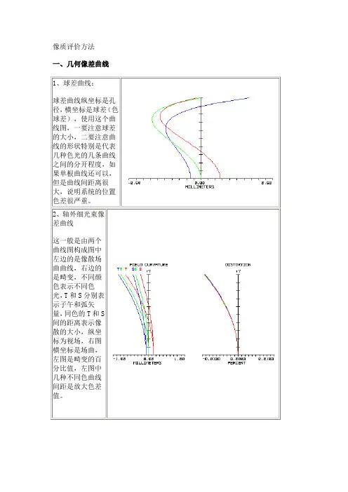
像质评价方法一、几何像差曲线1、球差曲线:球差曲线纵坐标是孔径,横坐标是球差(色球差),使用这个曲线图,一要注意球差的大小,二要注意曲线的形状特别是代表几种色光的几条曲线之间的分开程度,如果单根曲线还可以,但是曲线间距离很大,说明系统的位置色差很严重。
2、轴外细光束像差曲线这一般是由两个曲线图构成图中左边的是像散场曲曲线,右边的是畸变,不同颜色表示不同色光,T和S分别表示子午和弧矢量,同色的T和S间的距离表示像散的大小,纵坐标为视场,右图横坐标是场曲,左图是畸变的百分比值,左图中几种不同色曲线间距是放大色差值。
二、点列图——光束的光亮度由一点发出的许多光线经光学系统后,因像差使其与像面的交点不再集中于同一点,而形成了一个散布在一定范围的弥散图形,称为点列图。
,点列图是在现代光学设计中最常用的评价方法之一。
图中的几个图分别表示给定的几个视场上不同光线与像面交点的分布情况。
使用点列图,一要注意下方表格中的数值,值越小成像质量越好。
二根据分布图形的形状也可了解系统的几何像差的影响,如,是否有明显像散特征,或彗差特征,几种色斑的分开程度如何,有经验的设计者可以根据不同的情况采取相应的措施。
RMS RADIUS:均方根半径值;GEO RADIUS:几何半径(最大半径)三、传递函数调制传递函数MTF:一定空间频率下像的对比度与物的对比度之比。
能反映不同空间频率、不同对比度的传递能力。
一般而言,高频传递函数反映了物体细节传递能力,低频传递函数反映物体轮廓传递能力,中频传递函数反映对物体层次的传递能力。
1、MTF曲线图图中不同色的曲线表示不同视场的复色光(白光)MTF曲线,T和S分别表示子午和弧矢方向,最上方黑色的曲线是衍射极限。
横坐标是空间频率lp/mm(每毫米线对),纵坐标是对比度,最大是1。
曲线越高,表明成像质量越好。
[返回本章要点]2、传函与离焦关系曲线图此图表明对设定空间频率不同视场的子午、弧矢MTF与离焦量的关系,图中横坐标是离焦量,纵坐标是对比度,通过此图可以看出各视场的最佳焦面是否比较一致,MTF是否对离焦比较敏感。
Chapter X Image quality evaluation of optical system(光学系统像质评价)Introduction§10.1 Brightness of center disk and Rayleigh Judgement(中心点亮度和瑞利判断)§10.2 Resolving power(分辨率)§10.3 Spot diagram(点列图)§10.4 Optical transfer function(光学传递函数)IntroductionThe initial preliminary evaluation of the image quality provided by a particular system come from the blur circle formed by all the rays emitted by point objects in different field of view.This blur circle is called usually as diffused disk, spot diagram, point spread function.1. Geometrical aberration:The geometrical aberration is the residual aberration less than the tolerance of aberration or according to the curve of aberration. We determine the dimension of diffused disk.* Because of diffraction geometrical aberration can not describe the actualdistribution of energy of a point object.2. Wavefront aberration Rayleigh criterion (ifw 4λ'≤ the image quality is good; if w 10λ'≤the imagequality is perfect) is very simple, it is does not consider the defect area. Only used in small aberration system. (Peak to Valley: maximum wavefront aberration)3. The resolving power of an optical system has been the criterion most used for the quality of the image. It has been expressed by in terms of the maximum number of lines per millimeter. Moreover, the resolving power depends greatly on the contrast in object.4. Optical Transfer Function (OTF)OTF represents the property of an optical system considered as a transmitter of spatial frequence.* Even an ideally corrected system can only transmit spatial frequence below some limiting frequence-cutoff frequence.§10.1 Brightness of center disk and Rayleigh Judgement (中心点亮度和瑞利判断)1. Brightness of center diskStrehl Criterion:B r i g h t n e s s o f R a y l e i g h d i s k f o r a b e r r a t io n a l s y s t e m .B r i g h t n e s s o f R a y l e i g h d i s k f o r i d e a l s ys t e m S D =221222(0)1.(0)p ikwp w S D erd rd w πϕϕπϕ≠===⎰⎰Let C o m p l e x A m p l i t u d e a t i m a g e p p x y ϕ- exit pupil radiuslr -eye d istan ce z l '- Get 2120z ikl ik l pz r eerd rd l πωηϕϕλ'--='⎰⎰Expansion series of ikwe212xxex =++()222 .1S D k w w⎡⎤∴≈--⎢⎥⎣⎦12122211, w w rd rd w w rd rd ππϕϕππ==⎰⎰⎰⎰If S.D 0.8 th e system is p erfect,it n o tes th at th e cen ter en erg y o f rayleig h d isk is 0.84.≥Sample:2If , ()6844p w w λλϕ===22()684.0.8184(0)p p w S D w λϕϕ=====S.D0.8∴≥It corresponds to the Rayleigh criterion.w 4λ≤2. Rayleigh Judgement w 4λ'≤ The image quality is goodw 10λ'≤ The image quality is perfectConsidering only the maximum wavefront aberration, defocusing can improve the wavefront aberration. (Select the best image plane) The ration of the area (w4λ≤) to the whole area is not considered.The advantage is easy to calculate, applied in optical system with small aberration, such as telescope, microscope objective. Zemax: ① analysis ↙wavefront field settin g w avefro n t m ap w avelen g th in t erfero g ram ⎧⎧⎪⎪⎪⎨⎨⎪⎩⎪⎪⎩② windowOpd: determine the defect area§10.2 Resolving power(分辨率)Resolving power of a system will be of the order of 1σ, σ is the mean circlediameter of diffused disk.Rayleigh Judgement: the least resolving separation (LRS) of the two star images is given by the radius of Airy Disk. LRS=1 Airy radius Dove Judgement:LRS=0.85 Airy radius Ideal optical system:Telescope 140Dϕ︒= 120Dϕ︒=Microscope 0.61N A λσ=0.5N A λσ= Photographic 1475L N F=1800Fσ=Resolving power depend onc o n t r a s t o f a n o b j e c tillu im in atin g co n d itio n sen sitivety an d reso lu tio n o f d etecto r ⎧⎪⎨⎪⎩* Applied in large aberration system, such as photographic lens.Discussion:⑴ Resolving plate is a square-wave grating which consists of a series of light and darkness at progressively closer spacing.The resolving plate is high contrast, while object is lower contrast.b r i g h t m i n u s d a r k b r i g h t p l u s d a r kK =⑵ Some times it appears pseudo-resolving phenomenon, below cutoff frequence, higher frequence object can be resolved, this is because of phase-inverted.§10.3 Spot diagram(点列图)The entrance pupil is divided into a few equal area rings, equal number of rays pass through each zone. The points distribution in image plane represents the energy distribution.The diameter of the spot less than (0.03~0.01mm) is permitted, and it is depended on the detector.§10.4 Optical transfer function (光学传递函数)The base of OTF is Fourier analysis 1. ConceptAn incoherent optical system (incoherent illumination) can be considered as a low-pass linear filter of spatial frequencies. If sinusoidal intensity distribution (signal) is inputted into optical system, the output is also sinusoidal, but the contrast is reduced (K 1), phase is shifted (ϕ∆). The ration M 1/M and phaseϕ∆ are depends on the frequence.M: inputted object contrast M 1: outputted image contrast* The ratio M 1/M is called modulated transfer function (MTF) of an optical system, and ϕ∆ is called phase transfer function (PTF).Inputted:000co s 2(1co s 2)a a x x I I I I f x I f x I ππ=+=+m a x m i n00maxm in 00()()()()a a aa a I II I I I IM I I I I I I I -+--===+++-0 (1c o s 2)xII M f x π∴=+ After passing though optical system0 [1c o s (2)]x I I Mf x πϕ'=++∆a a I I M M'<'∴<M M T F M'=01M T F <<iP T FO T F M T F e-=Why take fine-wave distribution signal as inputted object? Because any object can be seen as be composed by a series of sine patterns with different frequence and different brightness.2. The condition of OTF1) linear condition:Energy distributions of object (image) satisfy linear superposition:● with incoherent illumination ● ground glass● optical system has larger numerical aperture2) space-invariableThere is the same point spread function (PSF) in any region of the image plane-isoplanatic condition.Object (image) is divided into many isoplanatic regions, each region has the same effect of diffraction and aberration.3. Expression of OTFIn order to calculate OTF the object (image) break down many points, mathematically is (,)x y δ. Object distribution:11111(,)(,)(,)o x y o x y x x yy d x d yδ∞=--⎰⎰Image distribution:(,)(,)(-,-)(,)(-,-)x y y I x y o x y h x x y y d xd y o x y h x x y y xββββ∞''''=⎰⎰''=*h – PSF (point spread function)Method 1: (,){(,)}{(,P S F x y P x y P x y *''''''=ℑℑ(,)(,), I t i s c a l l e d e x i t p u p i l f u n c t i o n.i k w x y P x y E e ''-''=(,)w a v e f r o n t a b e r r a t io n w x y w ηξ''''-即 -2(-){(,)}(,)i xx yy w x y w x y edxdyπ''''ℑ=⎰⎰ 2(-){(,)}(,)i xx yy w x y w x y e dxdyπ''*''ℑ=⎰⎰(,){(,)}x y O T F f f P SF x y ''=ℑMethod 2:(,)(,)(,)I x y o x y h x x y y ''''=*--Fourier transform(,)(,)(,)x y x y x y I f f o f f H f f =(,) .x y H f f O T F -Method 1: measured by interferometer; Method 2: measured by MTF instrument. Sample: Using linear spread function (LSF) LSF:()(,)h x h x y d y∞-∞=⎰Similarly:()()(,)x I x o x h x x d xβ∞-∞''=*⎰Fourier transform()()()x x x I f o f H f =OTF :2()()x x i f xH f h x ed xπ∞-∞=⎰, (x xf fλ=)- c o s s i nOT F : ()()c o s 2()s i n 2()()i x x x x r x veH f hxf xdx i h xf xdx H f iH f θθθππ∞∞-∞-∞=-∴=-=-⎰⎰MTF:()x H f =PTF: 1()()()x v x x rH f f tgH f φ-=Linear spread function (LSF) can be analogized by scanning slit.4. Example Let000()cos 2a x o x I I f x π=+Image distribution00000000000()()(co s 2) ()()co s 2a x x I x h x x I I f x d x I h x x d x I h x x f x d x ππ+∞-∞+∞+∞-∞-∞''=-+''=-+-⎰⎰⎰Suppose:000x x x d x d x x x x '=-⎫⇒=⎬'=-⎭Result:000()()()co s 2() {1()co s[2()]}x x x x I x I h x d x I h x f x x d xI H f f x f ππφ+∞+∞-∞-∞''=+-'=+-⎰⎰5. Application of OTF ① AnalysisLimiting frequence:curve Ⅱ better than Ⅰ.Low frequence:curve Ⅰbetter than Ⅱ.It means that lens Ⅰ has better image quality for low frequence object than lens Ⅱ.② Integrate the curve, the larger the area is, the better the lens quality is. The area represents the transmitted information magnitude.③ The advantage of using MTF as quality criterion is the ability to cascade the MTF curves of a lens and film by multiplying together the MTF values.l e n sf iM T F M T F M T F =⨯ * Notes that:If the illumination is perfectly coherent, the resolution drops to half, butthe contrast at the low frequence is great improved.6. The calculation of exit pupil function1(,)(,)(,)x y GO T F f f Px x y y P x y d xd y C*''=++⎰⎰OTF is the autocorrelation of exit pupil function,x y x y f f RRλλ''==R – Distance from ideal point to center of exit pupil. C – Constant 2(,)P x y d xd y=⎰⎰, used for normalized OTF.(,)0(,)i k w x yP x y E e-=E - Constant (amplititude), can be discarded.(,)w x y - wavefront aberration.-[(,)(,)](,)(,)0, o u t o f su p erp o sitio nik w x x y y w x y e P x x y y P x y *''++-⎧⎪''++=⎨⎪⎩'y zT T ww δδηζ''∂∂=='∂∂,x y ζη''-- i f ζ'∴= Tangential: (0,)(0,)co s 2sin 2yy y y T T P y y P y f i f πδπδ*'''+=+i fη'=Sagittal: (,0)(,0)cos 2sin 2z z z z T T P x x P x f i f πδπδ*'''+=+附一c o s xx x f f θλλ==Normally 1R f '==, x yx f y f λλ''∴==For geometrical optics, assume that λ tends towards zero, so we can write:(0,)(0,)y yw w y f w y f yλλ∂+-=∂(0,)(0,)2y y y ik w y f w y i f T ee λπδ'⎡⎤-+--⎣⎦∴=[](,0)(,0)2c o s 2s i n 2x x z ik w x f w x i f T x z x z eef T f T λπδπδπδ'-+--''∴==+* 这里的坐标(,)x y 即像差中出瞳(),ξη''。
所有光线在高斯面上仍不交于同一像点,并且不
9子午像点——子午细光束经球面折射后会聚于主光线上一点9弧矢像点——弧矢细光束经球面折射后会聚于主光线上一点s
t ts x x x ```−=像点(子午,弧矢)像面(子午,弧矢)
桶形畸变
枕形畸变
物
应合理选取光线进行光路计算
点列图中点的分布能够近似地代表像的能量分布
设该余弦基元的空间频率为μ,周期为p,振幅等于a,初无论是周期函数还是非周期函数,都可以把它们分解成频率、
振幅和位相不同的余弦函数(称为原函数的余弦基元)
对比传递因子,用MTFμ表示
(Phase Transfer Function) 称为位相传递函数,
Transfer Function)表示。
物面图形的对比度K为
1、作为目视系统,Ⅱ的分辨率较高
2、作为摄影系统,Ⅰ的分辨率较高
光学系统是一个空间频率低通的线性滤波器
例如: 电视摄像用的镜头,不要求高的分辨力,要求能对较低对比度的景物获得层次尽可能丰富的像,曲线Ⅰ好。
光刻用的镜头,物是对比度很高的黑白线条或图案,对像的要求主要是期望分辨力尽可能高,用曲线Ⅱ为宜。
原理:像点中心亮度值与MTF曲线的包容面积有对应关系。
在一定的截止频率范围内,只有获得较大的MTF 值才能传递较多的信息。