超低功耗-电池供电超过10年的无线传输模块
- 格式:doc
- 大小:1.55 MB
- 文档页数:2
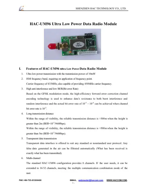
HAC-UM96Ul t r a Lo w P o we rDa t a Ra d i o Mo d ul eI.F e a t ur e s o f HAC-UM96u l t r a L o w P o we r Da t a Ra d i o Mo d ul e1.Ul t r a l o w p o we r t r a n s mi s s i o n wi t h t h e t r a n s mi s s i o np o we r o f 10mW2.I SM f r e q u e n c y b a n d, r e q u i r i n g o n a p p l i c a t i o n o f f r e q u e n c y p o i n t.Ca r r i e r f r e q u e n c yo f433MHz, a l s o c a p a b l e o f p r o v i d i n g 450MHz c a r r i e r f r e q u e n c y.3.Hi g h a n t i-i n t e r f e r e n c e a n d l o w B ER(B i t e r r o r R a t e)Ba s e d o n t h e GF SK mo d u l a t i o n mo d e, t h e h i g h-e f f i c i e n c yf o r wa r d e r r o r c o r r e c t i o n c h a n n e le n c o d i n g t e c h n o l o g y i s u s e d t o e n h a n c e d a t a’s r e s i s t a n c e t o b o t h b u r s t i n t e rf e r e n c e a n dr a n d o m i n t e r f e r e n c e a n d t h e a c t u a l b i t e r r o r r a t e o f 10-5 ~ 10-6 c a n b e a c h i e v e d wh e n c h a n n e lb i t e r r o r r a t e i s 10-2.4.Lo n g t r a n s mi s s i o n d i s t a n c eW i t h i n t h e r a n g e o f v i s i b i l i t y, t h e r e l i a b l e t r a n s mi s s i o n d i s t a n c e i s >300m wh e nt h e h e i g h t i sg r e a t e r t h a n 2m (B ER=10-3/9600b p s).W i t h i n t h e r a n g e o f v i s i b i l i t y, t h e r e l i a b l e t r a n s mi s s i o n d i s t a n c e i s >500m wh e n t h e h e i g h t i sg r e a t e r t h a n 5m (B ER=10-3/9600b p s).5.Tr a n s p a r e n t d a t a t r a n s mi s s i o nTr a n s p a r e n t d a t a i n t e r f a c e i s o f f e r e d t o s u i t a n y s t a n d a r d o r n o n s t a n d a r d u s e r p r o t o c o l. An yf a l s e d a t ag e n e r a t e d i n th e ai r c a n b e f i l t r a t e d a u t o ma t i c a l l y(W h a t h a s b e e n r e c e i v e d i se x a c t l y wh a t h a s b e e n t r a n s mi t t e d).6.Mu l t i-c h a n n e lTh e s t a n d a r d HAC-UM96 c o n f i g u r a t i o n p r o v i d e s8c h a n n e l s. I f t h e u s e r n e e d s, i t c a n b ee x t e n d e d t o 16/32 c h a n n e l s, me e t i n g t h e mu l t i p l e c o mmu n i c a t i o n c o mb i n a t i o n mo d e of t h eu s e r.7.Dual serial port, 3 interface modesHAC-UM96 provides 2 serial ports and 3 interfaces, with COM1 as the TTL level UART interface and COM2 as user defined standard RS-232/RS-485 interface (user only needs to plug/pull 1 bit short circuiter and energize it to mak e the definition).rge data buffer zoneInterface baud rate which is set before ex-factory is1200/4800/9600/19200/38400bps with format of 8N1/8E1 and user self-definition, allowing the transmission of long data frames at one time for more flexible programming by users. (If the user needs, it can also transmit the data in unlimited length at one time).9.Intelligent data control and the user doesn’t need to prepare excessive programsEven for semi duplex communication, the user doesn’t need to prepare excessive programs, only receiving/transmitting the data from the interface. HAC-UM96 will automatically complete the other operations, such as transmission/receiving conversion in the air, control, etc.10.Low power consumption and sleeping functionFor receiving, current is <30mA, transmitting current is <40mA, and sleep current is <20uA.11.High reliability, small and lightSingle chip radio-frequency integrated circuit and single chip MCU are used for lessened peripheral circuits, high reliability, and low failure rate.II.Ap p lic ation of series HAC-UM96ultra low p ower data radio module Series HAC-UM96ultra low power data radio module is suitable for:Wireless meter readingIndustrial remote control and remote testAutomatic data collecting systemBuilding automation, safety and security, powerhouse equipment wireless monitor, entrance control systemP OS system, wireless k eyboard, mouseIII.How to use series HAC-UM96ultra low p ower data radio module Series HAC-UM96ultra low power data radio module provides three interface modes including standard RS-232,RS-485 and UART/TTL levels allowing direct connection withcomputer, user’s RS-485 device, monolithic processor and other UART components for application. The schematic circuit of HAC-UM96 is shown below:1.Power supplyHAC-UM96 uses DC power supply with voltage of +3.3~5.5V.The working voltage can be reduced down to 3V based on the user’s needs.It can also share power supply with other equipment, however, the high quality power s upply with desirable ripple factor should be selected. If possible, 7805 chip or other voltage-stabilizing chip should be used for separate power supply. In addition, the reliable grounding must be used if there is other device in the system equipment. In case of failure to connect with the earth, it can form its own grounding but it must be absolutely separated from the municipal electric supply.Under working condition, transmission current is≤40mA, receiving current is≤30mA and sleeping current is ≤20uA.2.Definition of HAC-UM96 connecting terminalHAC-UM96 can supply one9-pin connector (J P1), and its definitions as well as connection method for terminals are shown in Table 1.Table 1: Definition of connecting pins and connection methodPin NoPinNameDescription Level Connected tothe terminalRemarks1GND Grounding of powersupply Grounding of power supply2Vcc Power supply DC+3.3~5.5V3RxD/TTL Serial data receivingend TTLTxD4TxD/TTL Serial data transmittingendTTLRxdCOM15SGND Grounding of the signal 6A(TxD) A of RS-485or TxD of RS-232A(RxD)7B(RxD) B of RS-485 or RxD of RS-232B(TxD)COM2See Page 3,48SLEEP Sleep control (input)TTL Sleep signal Low efficiencyt>15ms9RESET Reset (input)TTL Reset signal Negativeimpulse reset3.Sketch map of connection between HAC-UM96 and terminal equipment (see below)4.Setting of channel, interface and data format:Before using HAC-UM96, the user needs to make simple configuration based on its own needs to determine the channel, interface mode and data format.There is one group of 5-bit short-circuit j umper wire (JP2) on the upper right corner of HAC-UM96, defined as ABCDE respectively.Assuming the open circuit of j umper wire (without short circuiter) is mode 1 and short circuit of j umper wire (with short circuiter) is mode 0, then the configuration is as follows:a. Channel configuration:ABC j umper wires of JP2 provide 8 options, and the user can choose to use 0-7 channels through ABC j umper wires. Within one small communication network, as long as ABC j umper wire mode is same, there can be mutual communication.Table 2: Corresponding frequency points of 0~7 channelsChannel No.Frequency Channel No.FrequencyCBA=000(0)430.2000 MHz CBA=100(4)434.6940 MHzCBA=001(1)431.4288MHz CBA=101(5)434.2332MHzCBA=010(2)431.7360 MHz CBA=110(6)433.1580 MHzCBA=011(3)430.5072MHz CBA=111(7)433.9260MHzNote: The frequency points corresponding to each channel can be adjusted based on the user’s needs.A=1,B=1,C=1 (without short circuiter)A=0,B=0,C=0 (with short circuiter)b. Selection of interface mode:HAC-UM96 provides 2 serial ports. COM1 (Pin3 and Pin4 of JP1) is fixed as UART serial port of TTL level; COM2 (Pin6 and Pin7 of JP1) can choose interface mode through D of JP2:D=1 (without short circuiter) COM2 = RS-485D=0 (with short circuiter) COM2 = RS-232The following attention should be paid for the two serial ports provided by HAC-UM96:i.For the data received from the air, when HAC-UM96 transmits it to the terminalequipment through serial port, COM1 and COM2 output simultaneously, i.e. if the userconnects one device at COM1 and COM2 respectively, they can receive the datasimultaneously.ii.For the data transmitted from the terminal equipment and ready to transmit to the air, HAC-UM96 can only receive the data sent from either COM1 or COM2 but notsimultaneously.Suggestion: The user only connects to use one serial port of COM1 or COM2.c. Parity mode selection:HAC-UM96 can support no-parity or even parity modes of the serial communication UART, i.e.8N1/8E1. It can choose parity mode through E of JP2:E=1 (without short circuiter) Parity: 8E1 (even parity)E=0 (with short circuiter) Parity: 8N1 (no parity)I f j u mp e r i s a l t e r e d,i t b e c o me e f f e c t i v e a f t e r e l e c t r i f y.5.Transparent data transmissionTransparent data interface is offered to suit any standard or nonstandard user protocol. Any false data generated in the air can be filtrated automatically (What has been received is exactly what has been transmitted).6. Low Power Consumption (Sleep State) Function:HAC-UM96module supports the Sleep function that can further reduce its power consumption.In sleep state, the supply current consumption can be less than 20uA.We always disable this function as the factory default setting if it is not required. As the result, HAC-UM never entersa sleep state mistakenly in that case. If the sleep function is necessary, customers shouldindicate this in order so we can enable it before delivery.a. Using the Sleep function:When the SLP (SLEEP) signal on JP1 pin 8 is continuously high, HAC-UM keeps in sleep state.The SLP signal can convert HAC-UM from idle to sleep state in 10us after its rising edge. If the SLP signal reaches on HAC-UM receiving or transmitting data, this module cannot enter sleep state until this data group transmission completed.If the SLP (SLEEP) signal is continuou sly high, HAC-UM keeps in active state. The SLP signal can convert HAC-UM from sleep to active state in 1ms after its falling edge in order to ensure that CPU clock works stably again.To disable the sleep function for HAC-UM96, the SLEEP pin should be ground or zero.b. Application Notes:For those HAC-UM96 modules with the sleep function enabled, they may enter sleep state by error in case of improper power on. So we recommend that an additional reset signal is required for HAC-um after at least 150 ms of main CPU program delay when the module is powered on.7.Sketch map of structural size (see below):IV.Application of series HAC-UM96 network ingThe communication channel of HAC-UM96 is semi duplex, which is most suitable for the communication mode of point to multi-point. Under this mode, one master station must be set, and all of the rest are slave stations. A unique address is given to each station. The coordination of communication is controlled by master station that uses data frames containing address code to transmit data or command. Slave station will receive all of the data and command and compare the received address code with local address code. If they are different, the data will be deserted without any response. If those address codes are the same, it means the data is sent to the local. Slave station will make different responses according to the transmitted data or command and send back the data of response. All these jobs must be performed by upper protocol, and it is assured that there is only one transmitter-receiver in the state of transmission in the communication network at any instant moment so as to avoid the cross-interference.HAC-UM96 can also be used for point-to-point communication with easier operation. For the programming of serial port, all you have to do is to remember that its communication mode is semi duplex while always observing the time sequence of come-and-go for receiving and transmitting.V.Tech nical specification of HAC-UM96Modulation mode: GFSKWorking frequency: 429.00~433.30MHz (customization for 450~470MHz)Transmission power: 10dBmInterface data format: 8E1/8N1Receiving sensitivity:-112dBm@9600bpsWorking temperature: -10℃~60℃(customization for -30℃~70℃)Power supply:+3.3 ~ 5.5VDCDimension:47×26×10mmTransmitting current: ≤40mAReceiving current:≤30mAsleep current :<20μAInterface velocity: 9600b p sWorking humidity: 10%~90% relative humidity without condensationVI.Description of ty peFor HAC-UM96product type, HAC indicates the name of manufacturer Shenzhen HAC Technology Co., Ltd., UM96 indicates ultra low power, i.e. transmission power is 10dBm, and96 indicates that interface baud rate is 9600bps, and 1200bps is HAC-UM12.Note: The user can’t set the communication rate of HAC-UM96 itself. The user chooses when placing the order and it is already set when delivered from the factory.。
目录第一章概述 (3)1.1简介 (3)1.2特点功能 (3)1.3应用场景 (3)第二章规格参数 (3)2.1极限参数 (3)2.2工作参数 (4)第三章尺寸与引脚定义 (5)第四章推荐连线图 (7)第五章功能详解 (8)5.1模块复位 (8)5.2AUX详解 (8)5.2.1 无线接收指示 (8)5.2.2 无线发射指示 (8)5.2.3 模块正在配置过程中 (8)5.3.4 AUX注意事项 (9)第六章工作模式 (11)6.1模式切换 (11)6.2传输模式(模式0) (12)6.3RSSI模式(模式1) (12)6.4设置模式(模式2) (12)6.5休眠模式(模式3) (12)6.6快速通信测试 (13)第七章指令格式 (14)7.1出厂默认参数 (14)7.2工作参数读取 (14)7.3版本号读取 (14)7.4参数设置指令 (14)第八章硬件设计 (17)第九章常见问题 (18)9.1传输距离不理想 (18)9.2模块易损坏 (18)9.3误码率太高 (18)第十章焊接作业指导 (19)10.1回流焊温度 (19)10.2回流焊曲线图 (20)第十一章相关型号 (20)第十二章天线指南 (21)12.1天线推荐 (21)第十三章批量包装方式 (22)修订历史................................................................................. 错误!未定义书签。
关于我们................................................................................. 错误!未定义书签。
第一章概述1.1 简介E49-400T20S是一款超高性价比无线数传模块,它具有4种工作模式。
各种传输方式各具特点,可分别适用于多种应用场景。
E49-400T20S能完美支持工业级应用,出厂经过严格的测试,确保其工业可靠性和批量一致性。
长期以来,低成本、低功率、短距离的无线通讯市场一直存在着。
自从Bluetooth问世后,一度让工业控制、家用自动控制、玩具制造商等业者动心不已,而蓝牙的成本却让他们望尘莫及,这导致许多厂商放弃使用。
如今,这些行业厂商领导者都加入IEEE802.15.4联盟,负责制定ZigBee的物理层和媒体介入控制层。
IEEE802.15.4规范是经济,高效,低数据速率(<250 kbps),适用于个人区域网络和对等网格网络的2.4GHz和868/928MHz无线技术。
它是ZigBee应用层和网络层协议的基础。
ZigBee是一种新兴的低成本,低复杂度,低功耗,低数据速率,低成本无线网络技术,是无线标记技术和蓝牙技术之间的技术方案。
主要用于短距离无线连接。
它是基于802.15.4标准,在数千个微小的传感器之间协调实现通信。
这些传感器需要非常低的功耗,并且通过无线电波将数据从一个传感器传输到另一个传感器,因此它们的通信效率非常高。
多年来,无线技术已经开发出不同的分支机构,适用于不同领域。
最初,许多技术仅用于消费电子通信,如CDMA/GPRS,WI-FI,蓝牙等,但现在随着工业控制的需求,一些无线技术也被应用于工业领域。
就像下面介绍的ZigBee 技术一样。
通过使用这些技术可以解决传统控制因为没有通讯功能而无法实现集中监控的问题,这将操作维护人员从大量繁琐的工作中解放出来,大大减轻了系统的不利影响和人工成本开销。
一般来说,随着通信距离的增加,设备的功耗、系统成本、复杂性都在增加。
与现有的无线通信技术相比,ZigBee技术将是最低的功耗和成本的技术。
同时由于ZigBee技术的数据传输速度和通信范围偏低,ZigBee技术也适用于携带流量较少的数据流量。
所以ZigBee联盟预测了工业控制,消费电子,汽车自动化,农业自动化和医疗设备控制等主要应用领域。
Zigbeeg应用图如图1-1所示:图1-1二、IEEE802.15.4和ZigBee介绍IEEE无线个人区域网(PAN)工作组的IEEE802.15.4技术标准是ZigBee技术的基础。
HAC-EmBee-A11D HAC-EmBee-A11N2.4G低功耗无线数传模块(ZigBee)用户手册V 2.02.2 2013/10/25深圳市华奥通通信技术有限公司SHENZHEN HAC TELECOM TECHNOLOGY CO.,LTD地址 : 深圳市南山区西丽路4227号大学城创意园2栋6楼电话 : +86-755-23981078传真 : +86-755-23981007邮件:*****************************网址 : HAC EmBee ZigBee Series 深圳市华奥通通信技术有限公司高性能✧20dbm可视距离2.8km✧7dbm可视距离850m 低功耗✧20dbm发射电流145mA,接收电流38mA,休眠电流3uA✧7dbm发射电流42mA,接收电流29mA,休眠电流3uAMESH网络✧自动组网,自动路由,自动愈合✧点对点,点对多点传输✧最多高达16跳传输 使用简单✧AT命令✧API命令✧API远程AT命令✧透明传输符合标准✧Zigbee 2007 Pro✧A11 Profile高可靠性✧DSSS O-QPSK调制方式✧CSMA-CA 自动退避机制✧重发与应答机制高安全性✧网络层AES加密✧应用层AES加密目录1 EmBee模块 (6)1.1 EmBee模块尺寸及管脚顺序 (6)1.2 模块管脚分布 (7)1.3 模块性能参数 (8)1.3.1 HAC-EmBee-A11N参数 (8)1.3.2 HAC-EmBee-A11D参数 (9)2 EmBee模块操作 (10)2.1 UART串口介绍 (10)2.2 通信协议 (10)2.2.1 透明传输模式 (10)2.2.2 API传输模式 (11)2.3 AT命令模式 (11)2.3.1 进入AT命令模式 (12)2.3.2 发送AT命令 (12)2.3.3 AT命令响应 (12)2.3.4 退出AT命令模式 (13)2.4 回环功能 (13)2.4.1 透传模式的回环 (13)2.4.2 API模式的回环 (13)3 API操作 (14)3.1 API帧格式 (14)3.2 API帧 (15)3.2.1 AT命令帧(立即生效) (15)3.2.2 AT命令帧(不立即生效) (16)3.2.3 AT命令响应帧 (17)3.2.4 传输请求帧 (18)3.2.5 应用层可选的传输请求帧 (19)3.2.6 传输状态帧 (21)3.2.1 数据接收指示帧(AO=0) (22)3.2.2 数据接收指示帧(AO=1) (23)3.2.3 I/O接收指示 (24)3.2.4 节点发现指示 (26)3.2.5 模块状态指示帧 (28)3.2.6 远端AT命令请求帧 (29)3.2.7 远端AT命令响应帧 (30)4 AT命令 (32)4.1 地址命令 (32)4.2 网络命令 (34)4.3 射频参数命令 (36)4.4 串口参数命令 (37)4.5 I/O参数命令 (38)4.6 诊断参数命令 (41)4.7 AT命令参数 (42)4.8 休眠命令 (42)4.9 命令执行 (43)5 数字I/O和模拟I/O (45)5.1 本地I/O (45)5.1.1 AT命令模式下读取本地I/O电平值和采样值 (45)5.1.1 AT命令模式下配置本地I/O (46)5.1.2 API模式下配置本地I/O (47)5.2 远端I/O (47)5.2.1 API模式下配置远端I/O (47)6 EmBee ZigBee网络 (48)6.1 协调器 (48)6.2 路由器 (49)6.3 终端设备 (49)6.3.1 子节点与父节点关系 (50)6.3.2 子节点容量 (50)6.4 子节点工作过程 (51)6.5 父节点工作过程 (51)1EmBee模块1.1EmBee模块尺寸及管脚顺序EmBee模块的外形结构如下:管脚顺序从PIN1开始,逆时针依次至PIN20。
af790模块参数摘要:1.AF790 模块概述2.AF790 模块参数详解3.AF790 模块参数的应用实例正文:一、AF790 模块概述AF790 模块是一款高性能、低功耗的模块化器件,适用于各种无线通信系统。
其具有较高的接收灵敏度、强大的抗干扰能力和优秀的信号处理性能,可广泛应用于各种通信设备、电子设备等领域。
二、AF790 模块参数详解1.工作电压:AF790 模块的工作电压范围为3.3V-5V,具有较宽的电压范围,可适应不同的工作环境。
2.接收频率:AF790 模块的接收频率范围为30MHz-6GHz,覆盖了常用的无线通信频段,满足多种通信需求。
3.接收灵敏度:AF790 模块的接收灵敏度为-128dBm,具有较高的接收性能,可实现远距离通信。
4.功耗:AF790 模块的功耗为100mW,具有低功耗特性,适合长时间工作的设备。
5.接口:AF790 模块支持SPI、I2C 等接口,方便与其他器件进行通信和控制。
6.调制方式:AF790 模块支持GFSK、OOK 等调制方式,可根据实际应用需求进行选择。
7.传输速率:AF790 模块的传输速率可达1Mbps,满足大多数通信应用的需求。
8.工作温度:AF790 模块的工作温度范围为-40℃至+85℃,具有较宽的工作温度范围,适应不同环境。
三、AF790 模块参数的应用实例1.无线通信设备:AF790 模块可应用于无线路由器、无线网桥、无线传感器等设备,实现数据传输和通信功能。
2.电子设备:AF790 模块可应用于智能家居、智能穿戴、智能医疗等电子设备,实现无线数据传输和远程控制。
3.物联网设备:AF790 模块可应用于各类物联网设备,如智能农业、智能交通、智能物流等,实现数据采集和传输。
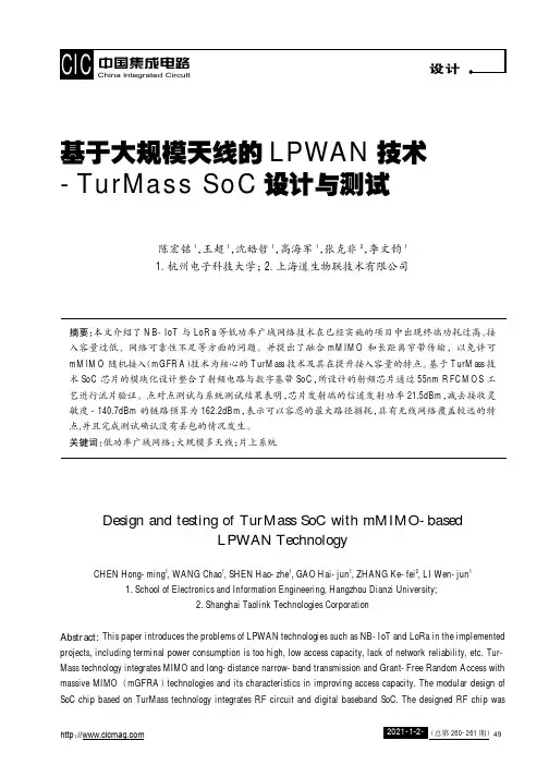
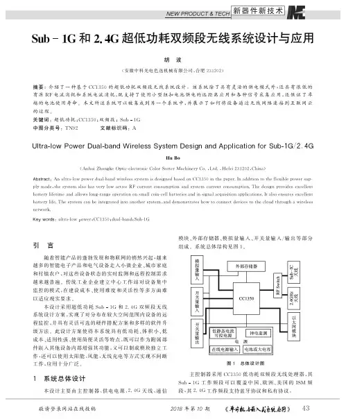
基于大规模天线的LPWAN技术-TurMass SoC设计与测试陈宏铭1,王超1,沈皓哲1,高海军1,张克非2,李文钧11.杭州电子科技大学;2.上海道生物联技术有限公司摘要:本文介绍了NB-IoT与LoRa等低功率广域网络技术在已经实施的项目中出现终端功耗过高、接入容量过低、网络可靠性不足等方面的问题。
并提出了融合mMIMO和长距离窄带传输,以免许可mMIMO随机接入(mGFRA)技术为核心的TurMass技术及其在提升接入容量的特点。
基于TurMass技术SoC芯片的模块化设计整合了射频电路与数字基带SoC,所设计的射频芯片通过55nm RFCMOS工艺进行流片验证。
点对点测试与系统测试结果表明,芯片发射端的信道发射功率21.5dBm,减去接收灵敏度-140.7dBm的链路预算为162.2dBm,表示可以容忍的最大路径损耗,具有无线网络覆盖较远的特点,并且完成测试确认没有丢包的情况发生。
关键词:低功率广域网络;大规模多天线;片上系统Design and testing of TurMass SoC with mMIMO-basedLPWAN TechnologyCHEN Hong-ming1,WANG Chao1,SHEN Hao-zhe1,GAO Hai-jun1,ZHANG Ke-fei2,LI Wen-jun11.School of Electronics and Information Engineering,Hangzhou Dianzi University;2.Shanghai Taolink Technologies CorporationAbstract:This paper introduces the problems of LPWAN technologies such as NB-IoT and LoRa in the implemented projects,including terminal power consumption is too high,low access capacity,lack of network reliability,etc.Tur-Mass technology integrates MIMO and long-distance narrow-band transmission and Grant-Free Random Access with massive MIMO(mGFRA)technologies and its characteristics in improving access capacity.The modular design of SoC chip based on TurMass technology integrates RF circuit and digital baseband SoC.The designed RF chip wasvalidated by55nm RFCMOS process.The results of point-to-point test and system test show that the link budget of transmitting power21.5dbm minus receiving sensitivity-140.7dbm is162.2dbm,which means the maximum path loss that can be tolerated,along with the characteristic of long range wireless network coverage and complete the test to confirm that there is no packet loss.Keywords:LPWAN;Massive MIMO;SoC引言物联网的本质是物体状态信息的感知、传输、应用和控制。
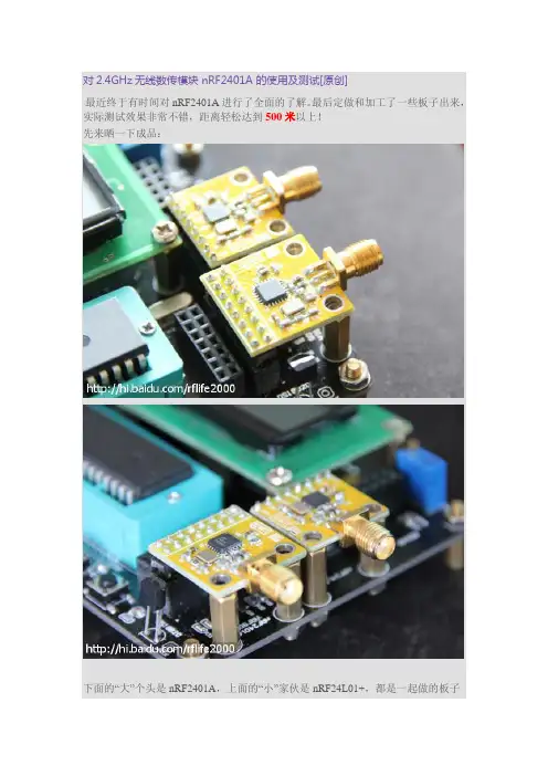
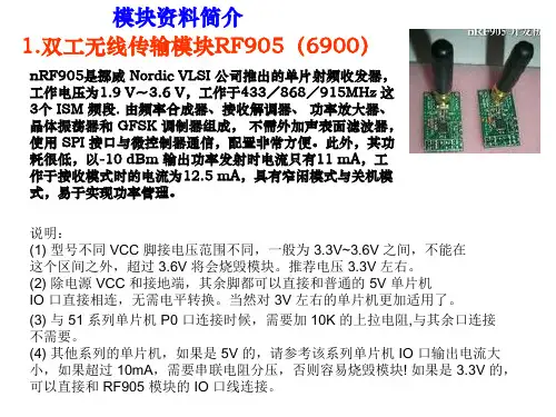
对2.4GHz无线数传模块 nRF2401A 的使用及测试[原创]最近终于有时间对nRF2401A进行了全面的了解。
最后定做和加工了一些板子出来,实际测试效果非常不错,距离轻松达到500米以上!先来晒一下成品:下面的“大”个头是nRF2401A,上面的“小”家伙是nRF24L01+,都是一起做的板子底板是无线开板,是为了方便调试、开发和测试准备的,之后的距离测试也是用这个——————华N——————丽O——————的V——————分A——————隔T——————线E——————nRF2401A算是比较老的产品了,大家应该早有听说或使用过。
最为使用最广泛的2.4GHz无线数传模块之一,nRF2401A当然具备很多及优势,现在来简单介绍一下:1.使用2.4GHz开放频段这里有点小注意:nRF2401A发射时的工作频率最高为2526MHz,接收时的最大工作频率为2524MHz。
2.高数据传输率,支持250kbps和1Mbps。
这个速率已经和蓝牙差不多了,所以这也是nRF2401A经久不衰的一个原因啦。
3.低功耗设计工作电压范围 1.9~3.6V。
工作在接收状态时的电流消耗为18mA,工作在发送模式功率为0dBm时消耗电流为13mA。
嗯,看起来很适合使用电池进行供电的场合使用?没错,现在的无线键盘鼠标里面多数就是使用的nRF2401A和nRF24L01方案。
4.简单的操作方式,减少MCU的工作负担。
nRF2401A除了同MCU之间使用简易的SPI通讯之外,还提供PWR_UP、DR1和DR2等直接操作引脚。
通过对PWR_UP操作可快速完成“上电”和“休眠”模式的切换。
而DR1、DR2可在nRF2401A完成数据接收后输出高电平,通知MCU准备读取接收数据。
5.省力的Shockburs传输模式这个“Shockburst”可是nRF2401A最吸引人的地方了,“Shockburst”是什么呢?通常的无线数传芯片在向空中发送数据包的时候需要先传送“前导字”,随后是“地址码”,接下来是“用户数据”,最后就是“CRC校验码”。
芯资讯低功耗广域网(LPWAN)LoRa远距离无线技术(第一版)王志杰2016-05-05版权所有,翻版必究目录1简介 (2)2低功耗广域网(LPW AN) (2)2.1低功耗广域网(LPW AN)的特点 (2)2.2LPWAN无线技术比较 (3)2.3LoRa联盟 (4)2.4中国LoRa应用联盟- CLAA (5)3LoRa技术 (6)3.1LoRa技术 (6)3.2LoRa无线技术主要特点 (6)4LoRa和LoRaW AN技术概览 (9)4.1简介 (9)4.2LoRa®是什么? (9)4.3LPWAN适合在那里? (10)4.4LoRaWAN是什么? (11)4.5LoRaWAN™区域概述 (14)4.6比较LPW AN技术选项 (16)4.7LPWAN成本对比传统系统 (17)5LoRaW AN解决方案 (18)5.1 简介 (18)5.2 解决方案平台架构 (19)5.3 产品 (20)5.4 网络服务器(Network Server) (21)5.5 网关(Gateway) (21)5.6 节点模块 (23)5.7 测试节点(Test Node) (25)5.8 开发设计 (26)5.8.1 NP-LINK Mote SDK (28)5.8.2 开源资源 (29)6LoRa应用案例 (29)1简介低功耗广域网(LPWAN)的是物联网领域中一个新的发展热点,由于其低功耗、广域的特点,非常适合于物联网大规模的部署。
在中国制造2025和智慧城市建设发展过程中,低功耗广域网应用将会越来越多。
下面可以从几个方面了解一下低功耗广域网:近距离和远距离:常见的近距离无线通信技术,如Wi-Fi、蓝牙等,通信距离一般几十米,若要覆盖一个地区一个城市的网络,则部署成本会较高。
而低功耗广域网无线通信距离可达几公里,甚至几十公里。
无线通信距离的增加,为物联网应用带来了新的发展空间,补上了物联网无线通信距离的短板,为物联网大规模的应用部署提供了技术支撑。
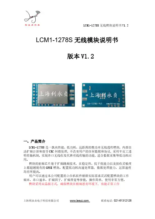
LCM1-1278S无线模块说明书V1.2 LCM1-1278S无线模块说明书版本V1.2一、产品简介LCM1-1278S是一款高性能、低功耗、远距离的微功率无线透传模块,内部自动扩频计算和前导CRC纠错处理,不改变用户的任何数据和协议,采用半双工透明传输机制,实现串口无线收发代替有线传输的功能,适合数据采集等低功耗应用。
模块的射频芯片基于扩频跳频技术,在稳定性、抗干扰能力以及接收灵敏度上都超越现有的GFSK模块。
配置低功耗高速处理器,数据处理能力、运算速度均有所提高。
用户可以通过本公司配置的上位机软件根据实际需求灵活配置模块的工作频率、串口速率、扩频因子、扩频带宽等参数,操作简单,使用非常方便。
模块采用双晶振方式,确保模块在极端恶劣环境下,也能正常工作LCM1-1278S 无线模块说明书V1.2类别指标名称无线模块无线射频调制方式LoRaTM 扩频频率范围420M-450M(中国)(其它频段可以定制)发射功率1dBm~20dBm 接收灵敏度-143dBm(50bps)传输速率扩频因子(SF)和带宽(BW)设置传输距离3000-5000米天线连接外置SMA 天线、弹簧天线、吸盘数据接口数据接口TTL 电平串口信号TxD,RxD 串口速率1200~115200bps 串口校验None,Even,Odd数据位8功耗输入电压DC 3.3V 最大发射电流≤140mA(20dBm)最大接收电流<16mA休眠电流<1.5uA(不带LDO)工作环境工作温度-40℃~85℃外观尺寸长*宽*高34.2*18.4*4(mm)LCM1-1278S无线模块说明书V1.2四、模块引脚定义标识功能备注GND电源地VCC电源 3.3VEN预留RX TTL RX数据接收,接客户TXTX TTL TX数据发送,接客户RXAUX指示控制脚用来唤醒客户端。
SET预留预留单片机管脚都是3.3V电平,如果用户是5V的MCU,为了稳定,建议做电平转换。
无线模块选型指南名称:无线模块选型指南NRF905/NRF24L01/CC1100/Si4432/CC1020/CC2500...型号:各型号综合介绍“物联网”概念风起云涌,无线应用大行其道。
如在选型阶段就正确确定最适合要求的型号,无疑能缩短开发周期,尽快实现无线应用。
本栏目旨在简要概括介绍各无线模块的性能特点,给您的无线选型提供初步参考“物联网”概念风起云涌,无线应用大行其道,如无线监控、无线抄表、无线点菜、传感网络、无线称重等领域。
以无线替代有线,是个必然的发展趋势。
在此情况下,作为无线应用厂商,应考虑如何快速地推出符合市场需求的无线应用产品,抢占市场的蓝海。
作为专业的无线模块设计及供应商,飞拓电子专注于无线通信领域的开发及应用,能提供齐全的无线基础性产品(无线模块),专业的开发指导,大大减少您公司产品的开发周期。
本栏目旨在简要概括介绍各无线模块的性能特点,给您的无线选型提供初步参考。
Si4432模块性能及特点:(1) 完整的FSK收发器(2) 工作频率433M免费ISM频段(430.24~439.75MHz),也可以工作于900.72~929.27MHz(3) 最大发射功率17dBm(4) 接收灵敏度高达-115 dBm(5) 传输速率最大128Kbps(6) FSK频偏可编程(15~240KHz)(7) 接收带宽可编程(67~400KHz)(8) SPI兼容的控制接口,低功耗任务周期模式,自带唤醒定时器(9) 低的接收电流(18.5mA),最大发射功率时的电流:73mA (10)空旷通讯距离可达800米以上(波特率9.6Kbps)RF903模块性能及特点:(1) 433MHz 开放ISM 频段免许可证使用(2) 最高工作速率50kbps,高效GFSK调制,抗干扰能力强,特别适合工业控制场合(3) 125 频道,满足多点通信和跳频通信需要(4) 内置硬件CRC 检错和点对多点通信地址控制(5) 低功耗3-3.6V 工作,待机模式下状态仅为2.5uA,TX Mode在+10dBm情况下,电流为40mA; RX Mode为14mA(6) 收发模式切换时间 < 650us(7) 模块可软件设地址,只有收到本机地址时才会输出数据(提供中断指示),可直接接各种单片机使用,软件编程非常方便(8) 增加了电源切断模式,可以实现硬件冷启动功能!(9) SPI接口—功能强大、编程简单,与RF905SE编程接口类似。
NB-IoT技术在智能水表中的应用研究摘要:随着移动互联技术的发展,NB-IoT技术在智能水表设计中的应用空间越来越广泛。
文章结合多年工作实践,以NB-IoT技术概述作为切入点,阐述基于NB-IoT技术智能水表设计方案,利用NB-IOT窄带物联网特性,通过移动运营商专用网络实现数据交互、通知、控制功能,使用NB-IOT技术的智能水表是新一代的物联网远传水表实现智能化识别、计量、定位、跟踪、监控和管理。
关键词:NB-IoT技术;智能水表;物联网;数据传输随着大数据技术的发展,智能水务是智慧城市发展的重要组成部分。
远程抄表、管网监测、运维调度等目标需求对水务业务设施的计量精度和联网性能提出更高要求。
2017年工信部发布的《关于全面推进移动物联网(NB-IoT)建设发展的通知》要求推广NB-IoT在细分领域的应用,逐步形成规模应用体系。
2020年印发的《关于深入推进移动物联网全面发展的通知》提出要面向能源表计等重点领域,推进移动物联网终端、平台等技术标准及互联互通标准的制定与实施。
实践证明将NB-IoT技术应用到智能水表设计中是智能水务建设发展的必然趋势。
一、NB-IoT技术在智能水表中的应用价值NB-IoT全称为Narrow Band-Internet of Things,窄带物联网卡,NB-IoT属于物联网范畴的一种技术。
NB-IoT基于现有蜂窝网络的技术,可以通过升级现网来快速支持行业市场需求,成为GUL网络上的第四种模式。
结合相关文献资料,NB-IoT技术具有以下优点:一是电池使用寿命长。
通过不完全统计NB-IoT电池使用寿命超过十年,低功耗是延长使用寿命的关键因素,NB-IoT技术是在通用移动通信技术的非连续接收功能基础上进行优化,其采取功耗节省模式和增强型非连续接收模式;二是容量大。
容量大是该技术广泛应用于计量设备的重要因素,例如NB-IoT单个小区就能够支持10万连接;三是成本低。
随着互联网技术的发展,NB-IoT成本优势在各行各业中的优势逐渐突显出来,每个模块的成本不足5美元,远远低于其他网络技术;四是覆盖广。
超低功耗无线模块APC240---功耗最低的微功率模块产品
APC240系列无线模块工作于免费433MHz与470MHz频段,采用SEMTECH公司的低功耗射频芯片sx1212与低功耗ST单片机,配合全新的无线休眠唤醒技术,产品功耗控制达到业界最领先水平。
对于电池供电设备,特别是无法安装大容量电池的嵌入式装置,无线模块的功耗高低往往是困扰长期供电运行的最大问题,目前市场上的无线透传模块都集成了MCU与射频芯片,仅仅射频芯片的接收电流最低就已经达到10mA左右,这还没有包含MCU的电流消耗,而APC240模块电流消耗极低,整个模块包含射频芯片和MCU的接收电流消耗只有3.2mA,功耗之低可见一斑,远远低于行业同类产品,这也是为什么称之为超低功耗模块的原因。
APC240发射功率10mW;发射电流:33mA;接收电流:3.2mA;休眠电流:1.5uA
传输距离:空旷400米
例如:电池是3.6AH锂亚电池,APC240接收电流为3.2mA,休眠电流1.5uA。
射频传输速率10Kbps,无线唤醒周期为1秒,唤醒搜索前导码时间平均约为4.5毫秒,那么,
电池的使用寿命:
=
3600mAH
(4.5ms/(1000ms+4.5ms))*3.2mA+0.0015mA
≈227337H≈(25.95年)
考虑到电池自放电与其它因素的放电消耗,电池寿命也可轻松达到十年以上,非常适用于水表/气表抄表、无线数据采集、报警器、温湿度监控装置等要求用电池长期工作的场合。
APC240B天线连接图。
ESP8266 WiFi模块用户手册目录术语和缩写 ....................................................... 错误!未定义书签。
1. 产品简介 ......................................................... 错误!未定义书签。
. 概述 ......................................................... 错误!未定义书签。
产品特性 ................................................. 错误!未定义书签。
模块封装 ................................................. 错误!未定义书签。
模块基本参数 ............................................. 错误!未定义书签。
. 硬件介绍 ..................................................... 错误!未定义书签。
. 功耗 ......................................................... 错误!未定义书签。
. 射频指标 ..................................................... 错误!未定义书签。
. 尺寸 ......................................................... 错误!未定义书签。
. WiFi 天线 .................................................... 错误!未定义书签。
. 推荐炉温曲线 ................................................. 错误!未定义书签。
深圳市安美通科技有限公司DVER 1.30APC300 超低功耗微功率无线传感器模块APC300模块是高度集成超低功耗微功率单向发射模块,模块采用了超低功耗单片机和高性能低功耗发射芯片,内置12bit 高精度ADC ,可以直接连接主流的各种数字与模拟传感器,如PT1000等热敏电阻,数字温湿度传感器等。
用户无需编写无线与传感器部分的软件,也不需要额外的MCU 和外围器件。
APC300模块提供了多个频道的选择,可在线修改串口速率,收发频率,发射功率,射频速率,发射间隔以及传感器类型等各种参数。
应用:z 高压电力线,开关柜测温 z 农业大棚温湿度采集 z 生鲜,疫苗冷链物流z 无线轴承,缸体及纺机温度监测 z 混凝土,矿井及隧道测温z 仓储,图书馆和博物馆温湿度监测 z 室内外温湿度监测 z 无线单向数据传输APC300模块能定时采集传感器数据并发送,模块可在2.1-3.6V 电压范围内工作,在10dBm 发射功耗仅仅14mA ,休眠功耗低至1.5uA ,合理的设定采集周期,通常一节普通的的锂亚电池(如ER18505)工作寿命可达数年至十几年。
特点:z 700米传输距离(3.125Kbps) z 2.1-3.6V 宽电压工作范围z 频率425-450,863-870,902-928MHz z 多频道可设,G FSK的调制方式 z 可设置定时采集时间间隔 z 可直接连接模拟与数字传感器 z 发射电流14mA@10dBm,待机电流1.5uA z 数年至十几年电池使用寿命APC300模块是单向的多通道嵌入式无线数传模块,能够连接各种传感器,并设置采集间隔周期,也可以设置成普通的单向数传模块,通过UART口接收上位机程序,可设置多个频道,步进为1KHz,发射功率最大10mW,体积22.4mm x 15.9mm x 2.4mm,很方便客户嵌入系统之内,APC300模块具有极低的功耗,非常适合于电池供电系统。
超低功耗无线模块---电池供电超过10年的无线传输模块
APC240系列无线模块工作于免费433MHz与470MHz频段,采用SEMTECH公司的低功耗射频芯片sx1212与低功耗ST单片机,配合全新的无线休眠唤醒技术,产品功耗控制达到业界最领先水平。
对于电池供电设备,特别是无法安装大容量电池的嵌入式装置,无线模块的功耗高低往往是困扰长期供电运行的最大问题,目前市场上的无线透传模块都集成了MCU与射频芯片,仅仅射频芯片的接收电流最低就已经达到10mA左右,这还没有包含MCU的电流消耗,而APC240模块电流消耗极低,整个模块包含射频芯片和MCU的接收电流消耗只有3.2mA,功耗之低可见一斑,远远低于行业同类产品,这也是为什么称之为超低功耗模块的原因。
APC240发射功率10mW;发射电流:33mA;接收电流:3.2mA;休眠电流:1.5uA
传输距离:空旷400米
例如:电池是3.6AH锂亚电池,APC240接收电流为3.2mA,休眠电流1.5uA。
射频传输速率10Kbps,无线唤醒周期为1秒,唤醒搜索前导码时间平均约为4.5毫秒,那么,
电池的使用寿命:
=
3600mAH
(4.5ms/(1000ms+4.5ms))*3.2mA+ 0.0015mA≈227337H ≈(25.95年)
考虑到电池自放电与其它因素的放电消耗,电池寿命也可轻松达到十年以上,非常适用于水表/气表抄表、无线数据采集、报警器、温湿度监控装置等要求用电池长期工作的场合。
APC240B天线连接图。