MODTRAN TP5文件参数设置说明
- 格式:pdf
- 大小:208.28 KB
- 文档页数:5
Nastran软件中的cfg配置文件设置Nastran软件中的cfg配置文件设置1. 使用Nastran软件中的cfg配置文件进行f06文件设置通常在计算完成后的f06文件前面有很长的介绍MSC各种软件模块功能的信息,该信息主要是对MSC软件进行相关的介绍。
当模型输出信息较多时,期望进行该类信息的整理。
解决该类问题,有以下方法:法1:C:\MSC.Software\MD_Nastran\20111\md20111\nast 目录下有一个news.txt文件,打开该文件就可以看到该信息为F06文件中的信息显示段。
将把里面的内容整理删除,保存文件退出。
法2:设置RC(Runtime confige)文件,在MSC安装目录下cfg文件夹中有一个配置文件(就是RC文件)。
用记事本打开在后面加上引号中内容“NEWS=NO $”。
以后不管用patran调用计算,还是直接填卡片计算都不会产生该类信息。
法3:使用卡片进行设置,就是在用NASTRAN计算时加参数NEWS=NO ,不过该方法每次都要加。
2. 使用Nastran软件中的cfg配置文件进行DBALL文件设置在软件计算过程中将产生dball文件,对于规模较大的模型,dball文件可以达到10G之多,而在计算中必须保证计算分区的可用空间足够大才能完成计算,故希望及时删除或者不生成dball文件,以便节约计算空间。
解决方法:在Nastran软件安装目录C:\MSC.Software\MSC.Nastran\conf 目录下NAST2011.rcf文件内直接添加:notify=noSCRATCH=yes文件保存并退出。
使用该设置后,deball文件在计算过程中还是会产生的,但在计算之后自动删除了。

Packet Tracer5.0 用户使用手册编辑:07网络16号黄汉文目录一、Packet Tracer5.0的介绍 (3)二、Packet Tracer5.0的安装与汉化 (3)三、Packet Tracer5.0的界面介绍和设备的选择 (8)四、Packet Tracer5.0和设备命令的介绍 (9)1.交换机支持的命令 (9)2.路由器支持的命令 (12)3.一个配置实例 (13)五、Packet Tracer5.0例子--配置VLAN (18)六、Packet Tracer5.0例子--VTP (20)七、Packet Tracer5.0例子--配置静态路由 (22)八、Packet Tracer5.0例子--配置单区域OSPF (25)九、Packet Tracer5.0例子--单臂路由 (28)十、Packet Tracer5.0例子--DHCP中继 (31)十一、Packet Tracer5.0例子--ACL简单的配置 (33)一、Packet Tracer5.0的介绍Packet Tracer 5.0是一款非常不错的Cisco(思科)网络设备模拟器,对于想考思科初级认证(如CCNA)的朋友们来说,Packet Tracer 5.0是非常不错的选择。
通常我们周围并没有那么多思科的设备供我们学习调试,参加培训费用很贵,上机实践的机会还是有限的,利用Packet Tracer 5.0练习思科IOS操作命令很不错的。
近日,在网上下载了思科CCNA640-802指导用书,打算根据此教程与诸位网友共同分享Packet Tracer 5.0的使用方法与技巧,也借此抛砖引玉。
二、Packet Tracer5.0的安装与汉化1.先从网上下载Packet Tracer5.0的安装程序和汉化包,并将它们解压出来,如下图2.点击安装程序,并点击Next,如下图3.再选择I accept the agreement,并点Next,如下图4.然后选择相应的安装路径,并点Next,如下图5.一直点Next,最后点install安装,安装程序的图标如下图6.将Packet Tracer+5.0汉化v1.0文件夹里面的chinese.ptl复制到Packet Tracer 5.0安装目录的languages文件夹里,如下图7.启动Packet Tracer 5.0,选择顶部菜单中的Options,然后再选择Preferences。

基于SPOT5的红树林遥感分类苏岫;赵冬至;王祥;钟才荣【摘要】Taking the Dongzhaigang National Mangrove Reserve in Hainan Island as example, we executed field measurements to obtain mangrove spectral data. On the basis of maximum likelihood classification purification mangrove information, combining with different kinds of mangrove spectral features and vegetation index difference, selected separability threshold, we established decision-making tree classification rule of SPOT5 images based on images between classifications, and tested its classification accuracy. Classification result shows that accuracy for each mangrove type reached 80% and the total accuracy added up to 90%. This research offers a foundation for operational remote sensing monitoring of mangrove ecosystem.%以海南岛东寨港国家级红树林自然保护区为例,实地测量了红树林等地物光谱,获取了较为准确的红树林的光谱特征;在采用最大似然分类法提纯红树林信息基础上,结合不同红树种类的光谱特征及植被指数差异,选定可分性阈值,建立决策树分类规则,对SPOT5图像进行种间分类,并检验其分类精度.结果显示,各红树种类的使用精度都达到80%以上,且总体精度达到90%以上,为红树林生态系统业务化遥感监测奠定基础.【期刊名称】《热带海洋学报》【年(卷),期】2012(031)006【总页数】7页(P128-134)【关键词】SPOT5卫星影像;红树林;光谱特征;遥感分类【作者】苏岫;赵冬至;王祥;钟才荣【作者单位】东寨港国家级自然保护区管理局,海南海口571129【正文语种】中文【中图分类】TP75红树林是生长在热带、亚热带地区的海岸潮间带或河流入海口, 以红树科植物为主, 受周期性海水浸淹的木本植物群落, 具有特殊的形态结构和生理特征, 对海岸带的环境保护、生态平衡以及生物多样性保护等有很重要的意义[1-2]。
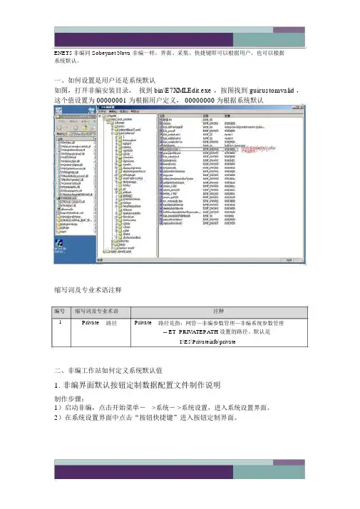
ENET5非编同 Sobeynet Nova 非编一样,界面、采集、快捷键即可以根据用户,也可以根据系统默认。
一、如何设置是用户还是系统默认如图,打开非编安装目录,找到 bin\E7XMLEdit.exe ,按图找到 guicustomvalid ,这个值设置为 00000001 为根据用户定义, 00000000为根据系统默认缩写词及专业术语注释编号缩写词及专业术语注释1Private路径Private路径是指:网管—非编参数管理—非编系统参数管理-- ET_PRIVATEPATH 设置的路径。
默认是I:\E5\Privateinfo\private二、非编工作站如何定义系统默认值1.非编界面默认按钮定制数据配置文件制作说明制作步骤:1)启动非编,点击开始菜单->系统- >系统设置,进入系统设置界面。
2)在系统设置界面中点击“按钮快捷键”进入按钮定制界面。
3)定制每个界面的显示按钮。
点击确认,退出界面设置,正常退出非编。
4)查找系统设置的private路径。
(Private 路径是指:网管—非编参数管理—非编系统参数管理 --ET_PRIVATEPATH设置的路径。
默认是 I:\E5\Privateinfo)CustomButton 文件夹下找到保存时间线属性的文件(文件名=用户名 _用户编码 .dat )这个文件记录的就是这个用户定义的默认按钮。
每个用户有自己的界面按钮定制文件,用户的配置文件保存最后一次登陆非编的设置5)如果想把默认按钮规定为程序系统默认,修改这个文件名为DefaultButtonbar.dat 。
把配置文件DefaultButtonbar.dat( 与版本相符合的配置文件 ) 拷贝到非编安装目录 \Nova\sys\DefaultData 文件夹下。
这样就是系统默认的默认按钮2.非编快捷钮定制数据配置文件制作说明制作步骤:1)启动非编,点击开始菜单- >系统- >系统设置,进入系统设置界面。


MODTRAN®5.2.2 USER’S MANUALA. Berk *, G.P. Anderson #, P.K. Acharya *, E.P. Shettle ^* Spectral Sciences, Inc.4 Fourth AvenueBurlington, MA 01803-3304(lex@)# Air Force Research LaboratorySpace Vehicles DirectorateAir Force Materiel CommandHanscom AFB, MA 01731-3010(Gail.Anderson@)^ Naval Research LaboratoryRemote Sensing DivisionWashington, DC 20375-5351May 2011SPECTRAL SCIENCES, INC.4 Fourth Ave.Burlington, MA 01803-3304AIR FORCE RESEARCH LABORATORYSpace Vehicles DirectorateAIR FORCE MATERIEL COMMANDHANSCOM AFB, MA 01731-3010TABLE OF CONTENTSSection Page 1. INTRODUCTION (5)1.1 Changes from Mod5.2.0 to Mod5.2.1 (5)1.2 Changes from Mod5.2.1 to Mod5.2.2 (5)1.3 Original Introduction (5)2. OVERVIEW OF INPUT DATA FORMAT (6)2.1 Listing of MODTRAN®5 CARDs and Their Format (7)3. CARD 1 (REQUIRED) – MAIN Radiation Transport DRIVER (10)4. CARD 1A (REQUIRED) –RADIATIVE TRANSPORT DRIVER CONT’D (13)5. OPTIONAL CARDs 1A1, 1A2, 1A3, 1a4, 1A5, 1a6, 1A7, 1b (18)6. CARD 2 (REQUIRED) – MAIN aerosol and cloud options (21)7. OPTIONAL CARD 2A+ (FLEXIBLE AEROSOL MODEL) (25)8. OPTIONAL CARD 2A (CLOUD MODELS) (26)8.1 CARD 2A Standard Form (CIRRUS CLOUD MODELS, ICLD = 18 or 19) (26)8.2 CARD 2A Alternate Form (WATER/ICE CLOUD MODELS, ICLD = 1 - 10) (26)9. OPTIONAL CARD 2B (ARMY VERTICAL STRUCTURE ALGORITHM) (29)10. OPTIONAL CARDs 2C, 2CY, 2C1, 2C2, 2C2X, 2C2Y, 2C3 (29)10.1 CARD 2C (30)10.2 CARDs 2C1, 2C2, 2C2X, 2C2Y (31)10.3 CARD 2C3 (33)11. OPTIONAL CARDs 2D, 2D1, 2D2 (USER-DEFINED AEROSOL AND CLOUD PARAMETERS) (34)11.1 CARD 2D (34)11.2 CARD 2D1 (34)11.3 CARD 2D2 (34)12. OPTIONAL CARDs 2E1 AND 2E2 (USER-DEFINED CLOUD PARAMETERS) (35)12.1 CARD 2E1 (35)12.2 CARD 2E2 (36)12.3 Alternate CARD 2E2 (37)13. CARD 3 (REQUIRED) – LINE-OF-SIGHT GEOMETRY (38)13.1 Standard CARD 3 (38)13.2 Alternate CARD 3 (TRANSMITTED SOLAR/LUNAR IRRADIANCE, IEMSCT = 3) (40)14. OPTIONAL CARDs 3A1 AND 3A2 (SOLAR / LUNAR SCATTERING GEOMETRY) (41)14.1 CARD 3A1 (41)14.2 CARD 3A2 (41)15. OPTIONAL CARDs 3B1, 3B2, 3C1-3C6 (USER-DEFINED SCATTERING PHASE FUNCTIONS) (42)15.1 CARD 3B1 (43)15.2 CARD 3B2 (43)15.3 CARDs 3C1-3C6 (43)16. CARD 4 (REQUIRED) - SPectral range and resolution (44)17.OPTIONAL CARDs 4A, 4B1, 4B2, 4B3, 4L1 and 4L2 (46)17.1 CARD 4A (46)17.2 CARD 4B1 (47)17.3 CARD 4B2 (50)17.4 CARD 4B3 (50)17.5 CARD 4L1 (50)17.6 CARD 4L2 (51)18. CARD 5 (REQUIRED) – Repeat run option (51)19. DEDICATION AND aCKNOWLEDGEMENTS (52)20. REFERENCES (53)APPENDIX A: MODTRAN® USER-SUPPLIED AEROSOL UPGRADES (55)A.1 User-Supplied Aerosol Spectral Parameters (ARUSS Option) (55)A.3 User-Supplied Aerosol Profiles (CARD 2C3) (57)A.4 Example tape5 File (58)APPENDIX B: NOVAM IN MODTRAN® (58)B.1 NOVAM Code (58)B.2 Incorporation into MODTRAN® (60)B.3 Some Results (61)B.4 NOVAM input and MODTRAN® input Files (61)B.5 Future Upgrades to NOVAM Implementation (64)B.6 Modifications to NOVAM to Code (64)B.7 References (65)APPENDIX C: MODTRAN® INSTALLATION (65)C.1 MODTRAN5.2.1 PC Installation Steps (65)C.2 MODTRAN5.2.1 MAC Installation Steps (65)C.3 MODTRAN5.2.1 linux (UNIX) Installation Steps (65)C.4 I/O Files (66)APPENDIX D: BAND MODEL FILES FOR USER-DEFINED SPECIES (67)APPENDIX E: BINARY OUTPUT OPTION (68)APPENDIX F: SPECIAL DISORT OPTION FOR ATMOSPHERIC CORRECTION (69)APPENDIX G: MODTRAN FREQUENTLY ASKED QUESTIONS (FAQ) ............................................... V olume 2LIST OF TABLESTable Page Table 1. Columns List Allowed Values of MODTRAN®CARD 1Input Parameters MODTRN, SPEED, MODEL ITYPE, IEMSCT, IMULT, MDEF, NOPRNT and SURREF. (13)Table 2. Shows the Value of IVULCN Corresponding to the Different Choices of Extinction Coefficient Model and the Vertical Distribution Profile. (22)Table 3. MODTRAN® CARD 2 Input Parameters: IHAZE, ISEASN, IVULCN, VIS (23)Table 4. Default Wind Speeds for Different Model Atmospheres Used with the Navy Maritime Model (IHAZE = 3) (24)Table 5. MODTRAN® CARD 2 Input Parameter: ICLD (25)Table 6. Default Aerosol Region Boundaries. (26)Table 7. Properties of the MODTRAN® Cumulus and Stratus Type Model Clouds. (27)Table 8. Association of the JCHAR(J) Index (J = 1, 14) with the Variables P, T & WMOL. (31)Table 9. Various Names for the Heavy Molecular Gases, (WMOLX(J), J = 1, 13) (32)Table 10. VARSPC Fixed (Required) Wavelength Grid for the Multiply Read CARD 2D2 (35)Table 11. Default Values of the Earth Radius for Different Model Atmospheres. (38)Table 12. Allowed Combinations of Slant Path Parameters (40)Table 13. CARD 3A2: Options for Different Choices of IPARM (42)Table 14. MODTRAN® CARD 5 Input Parameter: IRPT. (52)1. INTRODUCTION1.1 Changes from Mod5.2.0 to Mod5.2.1Most changes in this revision are minor, such as correcting comments or removing unused source code. The more important changes are listed below:Corrected error in calculation of spherical albedo term in <rootname>.acd file;Corrected error in <rootname>.7sc brightness temperatures for nanometer based response functions;Eliminated geometry problem most prevalent for line-of-sight paths that terminate near a tangent point;Introduced the 2009 series of band model parameter data based on HITRAN2008 with 2009 updates.Added the <rootname>.wrn output file which contains a duplicate listing of all warning and errormessages written to the <rootname>.tp6 and <rootname>.tp8 files;Modified source for compatibility to GNU compilers and FORTRAN77; andEliminated DISORT scaling of thermal radiance contributions.1.2 Changes from Mod5.2.1 to Mod5.2.2The number of changes in this revision is small, and they are delineated below:Mod5.2.1 had an error in its treatment of the boundary term for down-looking radiance calculationswhich used DISORT multiple scattering; the sensor-to-ground attenuation was being modeled usingthe true transmittance when the delta-M transmittance should have been used. For particularwavelength bins, spectral radiances could be in error by as much as a few percent.MODTRAN *.tp6 output file lists the vertical and line-of-sight total path 550nm extinction opticaldepths for molecular scattering, the aerosol components and cirrus clouds. For calculations in thethermal infrared (TIR), for example, the visible wavelength optical depths are not particularly helpful.MODTRAN *.tp6 output file now also lists the vertical and line-of-sight total path extinction opticaldepths at the central frequency of the input spectral range for molecular scattering, the aerosolcomponents and cirrus clouds.The MODTRAN headed, which previously was only written to the *.tp6 file, is now included in thestandard output and in the *.wrn file. The header has been modified to remind users who obtainMODTRAN via a Government Purpose Use license that their copy of the model is only to be used forGovernment Purposes as described in the license. Finally, the header is now only written once to eachfile.MODTRAN now includes a frequently asked questions (FAQ) document. It is listed as Appendix G ofthis document, but distributed in a separate volume.1.3 Original IntroductionMODTRAN®[Berk et al., 1989; Berk et al., 1998; Berk et al., 2000] serves as the U.S. Air Force (USAF) standard moderate spectral resolution radiative transport model for wavelengths extending from the thermal Infrared (IR) through the visible and into the ultraviolet (0.2 to 10,000.0 m). The spectroscopy of MODTRAN®5.2.2 is based on HITRAN2008 line compilation (Rothman et al., 1992; Rothman et al., 1998) with updates through June, 2009. The original MODTRAN® 1 cm-1 statistical band model was developed collaboratively by Spectral Sciences, Inc. and the USAF Research Laboratory to provide a fast alternative to the first principles, high accuracy line-by-line (LBL) radiative transport approach. Comparisons between MODTRAN® and LBL [Clough and Kneizys, 1979; Clough et al., 1981; Clough, 1988; and Snell et al., 1995]. Comparisons between MODTRAN® and the LBL model FASE (FASCODE for the Environment) [Clough et al., 1992; Clough and. Iacono, 1995; Clough et al., 2005] spectral transmittances and radiances show agreement to within a few percent or better in the thermal IR. FASE shares its LBL line shape fitting algorithms with LBLRTM, which evolved from FASCODE; see, for instance, Clough et al., 1992; Clough and. Iacono, 1995; Clough et al., 2005]. The MODTRAN®model includes flux and atmosphere-scattered solar calculations, essential components in analysis of near-IR and visible spectral region data that are not readily generated by LBL models.Technical descriptions of the MODTRAN®5 approach are available from a variety of sources. The original MODTRAN®2 code and many of the MODTRAN®3 upgrades are described in the 1996 report "MODTRAN® 2/3Report and LOWTRAN 7 Model" [Abreu and Anderson, 1996]. The current documentation incorporates material from that report, from Section 3 of the 1988 Users Guide to LOWTRAN7 [Kneizys et al., 1988], from the 1989 Air Force Research Laboratory (AFRL) report on the MODTRAN® band model [Berk et al., 1989], and from the 1996 Spectral Sciences, Inc. report on the cloud and rain model upgrades [Berk and Anderson, 1995]. Articles [Bernstein et al., 1995; Berk et al., 1998] discuss improvements to the band model. P lease email “Gail P. Anderson” <Gail.Anderson@>; “Michael L Hoke” <Michael.Hoke@> and / or “Alexander Berk” <lex@> for additional information on MODTRAN®5.MODTRAN®5 upgrades and improvements take the utility and science of the code to a new level, which includes, among other features, a much finer spectroscopy – spectral resolution can now be as fine as 0.1 cm-1– and the ability to handle new species not already included in the built-in profile and molecular parameter files. A summary of new features include:Reformulating the band model parameters and radiation transport formalism to increase the resolutionof MODTRAN® spectral calculations to 0.1 cm-1;Increasing the TOA solar database resolution to 0.1 cm-1;Incorporating code interface changes between MODTRAN® and DISORT to increase its speed andaccuracy of multiple scattering calculations;Upgrading MODTRAN®to perform spectral radiance computations for auxiliary molecules (byincluding their concentrations and spectral parameters) that are not part of the traditionalMODTRAN® database; Band models are provided for all HITRAN molecular species;Incorporating effect of a thin layer of water, which can either simply wet the ground or accumulate onit, on radiance computations;Capability to model a boundary layer aerosol whose extinction coefficient obeys the Angstrom law orto modify the extinction of a model aerosol with an Angstrom law perturbation;Capability to determine the spherical albedo and reflectance of the atmosphere and diffusetransmittance from a single MODTRAN® run;Ability to include only the solar contribution to multiple scattering and ignore the thermal componentwhere it is not significant;Option to write spectral output in binary, and a utility to convert the binary output to ASCII;Capability to process several tape5 input files by a single execution of MODTRAN®;Upgrade to the MODTRAN®-DISORT interface so that only a single parameter (MXCMU in routinePARAMS.h) needs to be modified to change the maximum number of streams available for DISORTruns.Added dithering of the solar angle in cases where the DISORT particular solution to the solar problemwas unstable.And more ….These user instructions for MODTRAN®5.2.2 describe each input in the MODTRAN®input files, tape5 or rootname.tp5.2. OVERVIEW OF INPUT DATA FORMATMODTRAN®5 makes it easy for the users to keep track of input and output (I/O) files. A MODTRAN® input file named either 'mod5root.in' or 'MOD5ROOT.IN' contains a list of file root names. If 'mod5root.in' does not exist, MODTRAN®checks for the existence of a 'MOD5ROOT.IN' file. If neither of these files exists, MODTRAN® I/O files are the traditional ones: 'tape5', 'tape6', 'tape7', 'tape8', etc. If a root name file exists and its very first line contains a non-null string (maximum length is 80 characters), this string is treated as a prefix. If the string consists of all blanks or is a null string, the traditional I/O file names are assumed. The root name should contain no embedded blanks; leading and trailing blanks are properly ignored. If the rootname file has the extension “.tp5”, this extension is also ignored. The character string is used as a prefix for the I/O files whose names have mnemonic suffixes. As an example, if the string is Denver, the MODTRAN® I/O files will have these names:Overview of Input Data FormatDenver.tp5(corresponding to tape5)Denver.tp6(corresponding to tape6)Denver.tp7(corresponding to tape7)Denverb.tp7(corresponding to tape7b)Denver.tp8(corresponding to tape8)Denverb.tp8(corresponding to tape8b)Denver.7sc(corresponding to tape7.scn)Denver.7sr(corresponding to tape7.scr)Denver.plt(corresponding to pltout)Denverb.plt(corresponding to pltoutb)Denver.psc(corresponding to pltout.scn)Denver.clr(corresponding to clrates)Denver.chn(corresponding to channels.out)Denver.flx(corresponding to specflux)Denver.acd(corresponding to atmcor.dat)A useful feature of MODTRAN®5 is the ability to process several input files in a single execution of MODTRAN®. To accomplish this, list the rootname of each input file as consecutive lines (without intervening blank lines) in 'mod5root.in' or 'MOD5ROOT.IN'. When the user executes MODTRAN®, each input ‘.tp5’ file, whose rootname is listed in 'mod5root.in' or 'MOD5ROOT.IN', is processed until the first blank line is encountered. Any ‘.tp5’ file whose rootname is encountered after the first blank line is not processed.As noted above, MODTRAN®is controlled by a input file, 'tape5' or 'rootname.tp5', which consists of a sequence of six or more formatted CARDS (inputs lines). The input file format is summarized below. With the exception of file names, character inputs are case insensitive. Also, blanks are read in as zeroes for numerical inputs, and as default values otherwise. Detailed descriptions of the card formats and parameters are given in the following sections.2.1 Listing of MODTRAN®5 CARDs and Their FormatIn the following, optional cards are indented. The mandatory input CARDS are CARD 1, CARD 1A, CARD 2, CARD 3, CARD 4 and CARD 5. Newer inputs are in Italics. Note that all floating point inputs are entered using a ‘Fn.0’ format; this format will properly read any floating point entry, e.g. ‘1.234’, AND will also properly read integers as floating point real variables, (either 1234. or 1234 with no decimal).CARD 1: MODTRN, SPEED, BINARY, LYMOLC, MODEL, T_BEST, ITYPE, IEMSCT, IMULT, M1, M2, M3, M4, M5, M6, MDEF, I_RD2C, NOPRNT, TPTEMP, SURREFFORMAT (4A1, I1, A1, I4, 10I5, 1X, I4, F8.0, A7)CARD 1A:DIS, DISAZM, DISALB, NSTR, SFWHM, CO2MX, H2OSTR, O3STR, C_PROF, LSUNFL, LBMNAM, LFLTNM, H2OAER, CDTDIR, SOLCON, CDASTM, ASTMC, ASTMX, ASTMO,AERRH, NSSALBFORMAT(3A1, I3, F4.0, F10.0, 2A10, 2A1, 4(1X, A1), F10.0, A1, F9.0, 3F10.0, I10) CARD 1A1:USRSUNFORMAT (A256) (If LSUNFL = 'T') CARD 1A2: BMNAMEFORMAT (A256) (If LBMNAM = 'T', 't', '4' or '2') CARD 1A3: FILTNMFORMAT (A256) (If LFLTNM = 'T') CARD 1A4: DATDIRFORMAT (A256) (If CDTDIR = 'T')Overview of Input Data FormatCARD 1A5: (S_UMIX(IMOL), IMOL = 4, 12)FORMAT (9F5.0) (If C_PROF = 1, 3, 5 or 7) CARD 1A6: (S_XSEC(IMOL), IMOL = 1, 13)FORMAT (13F5.0) (If C_PROF = 2, 3, 6 or 7) CARD 1A7: (S_TRAC(IMOL), IMOL = 1, 16)FORMAT (16F5.0) (If C_PROF = 4, 5, 6 or 7) CARD 1B:(AWAVLN(ISSALB), ASSALB(ISSALB), ISSALB=1, NSSALB)FORMAT ((8F10.0)) (If NSSALB > 0) Alternate CARD 1B:ACOALB, RHASYMFORMAT(2F10.0) (If NSSALB < 0) CARD 2:APLUS, IHAZE, CNOVAM, ISEASN, ARUSS, IVULCN, ICSTL, ICLD, IVSA, VIS, WSS, WHH, RAINRT, GNDALTFORMAT (A2, I3, A1, I4, A3, I2, 3I5, 5F10.0)CARD 2A+:ZAER11, ZAER12, SCALE1, ZAER21, ZAER22, SCALE2, ZAER31, ZAER32, SCALE3, ZAER41, ZAER42, SCALE4FORMAT ((3(1X, F9.0), 20X, 3(1X, F9.0))) (If APLUS = 'A+') CARD 2A:CTHIK, CALT, CEXTFORMAT (3F8.0) (If ICLD = 18 or 19) Alternate CARD 2A:CTHIK, CALT, CEXT, NCRALT, NCRSPC, CWAVLN, CCOLWD, CCOLIP, CHUMID, ASYMWD, ASYMIPFORMAT (3F8.0, 2I4, 6F8.0) (If 0 < ICLD ≤ 10) CARD 2B:ZCVSA, ZTVSA, ZINVSAFORMAT (3F10.0) (If IVSA = 1) CARD 2C:ML, IRD1, IRD2, HMODEL, REE, NMOLYC, E_MASS, AIRMWTFORMAT(3I5, A20, F10.0, I5, 2F10.0) (If MODEL = 0, 7 or 8; & I_RD2C = 1) CARD 2CY: (YNAME(I), I=1, NMOLYC)FORMAT ((8A10)) (If NMOLYC > 0) CARDs 2C1, 2C2, 2C2X, 2C2Y and 2C3 (as required) are each repeated ML times.CARD 2C1:ZM, P, T, WMOL(1), WMOL(2), WMOL(3), (JCHAR(J), J = 1, 14), JCHARX, JCHARY FORMAT 6F10.0, 14A1, 1X, 2A1)CARD 2C2:(WMOL(J), J = 4, 12)FORMAT (8F10.0, /F10.0) (If IRD1 = 1) CARD 2C2X:(WMOLX(J), J = 1, 13)FORMAT (8F10.0, /5F10.0) (If MDEF = 2 & IRD1 = 1) CARD 2C2Y: (WMOLY(J), J = 1, NMOLYC)FORMAT ((8F10.0)) (If NMOLYC > 0 & IRD1 = 1) CARD 2C3:AHAZE, EQLWCZ, RRATZ, IHA1, ICLD1, IVUL1, ISEA1, ICHRFORMAT (10X, 3F10.0, 5I5) (If IRD2 = 1) CARD 2C3: AHAZE(1), RRATZ, AHAZE(2), AHAZE(3), AHAZE(4)FORMAT(10X, F10.0, 10X, 4F10.0) (If IRD2 = 2) CARD 2D:(IREG(N), N = 1, 2, 3, 4)FORMAT (4I5) (If IHAZE = 7, ICLD = 11 or ARUSS=’USS’)CARDs 2D1 and 2D2 pairs are repeated for each N (1 to 4) for whichIREG(N) > 0 and ARUSS=USS or IREG(N) ≠ 0 and (IHAZE=7 or ICLD=11)CARD 2D1:AWCCON, AERNAMFORMAT (F10.0, A70)CARD 2D2:(VARSPC(N, I), EXTC(N, I), ABSC(N, I), ASYM(N, I), I = l, 2, ..., I max)If ARUSS = 'USS' & IREG(N) > 1, then I max = IREG(N); Else I max = 47 FORMAT ((3(F6.2, 2F7.5, F6.4)))CARD 2E1:(ZCLD(I, 0), CLD(I, 0), CLDICE(I, 0), RR(I, 0), I = 1, NCRALT)FORMAT ((4F10.5)) (If ICLD = 1 - 10, NCRALT 2, MODEL < 8) Alternate CARD 2E1:(PCLD(I, 0), CLD(I, 0), CLDICE(I, 0), RR(I, 0), I = 1, NCRALT)FORMAT ((4F10.5)) (If ICLD = 1 - 10, NCRALT 2, MODEL = 8) CARD 2E2:(WAVLEN(I), EXTC(6, I), ABSC(6, I), ASYM(6, I), EXTC(7, I), ABSC(7, I), ASYM(7, I),I = 1, NCRSPC)FORMAT ((7F10.5)) (If ICLD = 1 - 10, NCRSPC 2) Alternate CARD 2E2:C FILE, CLDTYP, CIRTYPFORMAT ((A256)) (If ICLD = 1 - 10, NCRSPC = 1) CARD 3: H1, H2, ANGLE, RANGE, BETA, RO, LENN, PHIFORMAT (6F10.0, I5, 5X, 2F10.0)Alternate CARD 3:H1, H2, ANGLE, IDAY, RO, ISOURC, ANGLEMFORMAT (3F10.0, I5, 5X, F10.0, I5, F10.0) (If IEMSCT = 3) CARD 3A1:IPARM, IPH, IDAY, ISOURCFORMAT (4I5) (If IEMSCT = 2 or 4) CARD 3A2: PARM1, PARM2, PARM3, PARM4, TIME, PSIPO, ANGLEM, GFORMAT (8F10.0) (If IEMSCT = 2 or 4) CARD 3B1: NANGLS, NWLFFORMAT (2I5) (If IEMSCT = 2 or 4; IPH = 1)CARD 3B2:(ANGF(I), F(1, I, 1), F(2, I, 1), F(3, I, 1), F(4, I, 1), I = l, NANGLS)FORMAT (5F10.0) (If IEMSCT = 2 or 4; IPH = 1; NWLF = 0) CARD 3C1:(ANGF(I), I = 1, NANGLS)FORMAT (8F10.0) (If IEMSCT = 2 or 4; IPH = 1; NWLF > 0) CARD 3C2:(WLF(J), J = 1, NWLF)FORMAT (8F10.0) (If IEMSCT = 2 or 4; IPH = 1; NWLF > 0) In CARDs 3C3-3C6, 'IANG' is angle index as in CARD 3C1and 'JWAV' is the wavelength index as in CARD 3C2.CARD 3C3:(F(1, IANG, JWAV), JWAV = 1, NWLF)FORMAT (8F10.0) (If IEMSCT = 2 or 4; IPH = 1; NWLF > 0) CARD 3C4:(F(2, IANG, JWAV), JWAV = 1, NWLF)FORMAT (8F10.0) (If IEMSCT = 2 or 4; IPH = 1; NWLF > 0) CARD 3C5: (F(3, IANG, JWAV), JWAV = 1, NWLF)FORMAT (8F10.0) (If IEMSCT = 2 or 4; IPH = 1; NWLF > 0) CARD 3C6:(F(4, IANG, JWAV), JWAV = 1, NWLF)FORMAT (8F10.0) (If IEMSCT = 2 or 4; IPH = 1; NWLF > 0) CARD 4:V1, V2, DV, FWHM, YFLAG, XFLAG, DLIMIT, FLAGS, MLFLX, VRFRACFORMAT (4F10.0, 2A1, A8, A7, I3,F10.0)CARD 4A:NSURF, AATEMP, DH2O, MLTRFLFORMAT (I1, 2F9.0, A1) (If SURREF = 'BRDF' or 'LAMBER') The set of CARD4B1, 4B2, and 4B3 inputs is repeated NSURF times.CARD 4B1:CBRDFFORMAT (A80) (If SURREF = 'BRDF') CARD 4B2:NWVSRF, SURFZN, SURFAZFORMAT (*) (If SURREF = 'BRDF') CARD 4B3 is repeated NWVSRF times.CARD 4B3:WVSURF, (PARAMS(I), I = 1, NPARAM)FORMAT (*) (If SURREF = 'BRDF')CARD 4L1:SALBFLFORMAT (A256) (If SURREF = 'LAMBER') CARD4L2 is repeated NSURF times.CARD 4L2:CSALBFORMAT (A80) (If SURREF = 'LAMBER') CARD 5: IRPTFORMAT (I5)3. CARD 1 (REQUIRED) – MAIN RADIATION TRANSPORT DRIVERAlthough CARD 1 format has been modified over the years, the format is backward compatible if inputs are right justified.CARD 1: MODTRN, SPEED, BINARY, LYMOLC, MODEL, T_BEST, ITYPE, IEMSCT, IMULT, M1, M2, M3, M4, M5, M6, MDEF, I_RD2C, NOPRNT, TPTEMP, SURREFFORMAT (4A1, I1, A1, I4, 10I5, 1X, I4, F8.0, A7)MODTRN selects the band model algorithm used for the radiative transport, either the moderate spectral resolution MODTRAN®band model or the low spectral resolution LOWTRAN band model. LOWTRAN spectroscopy is obsolete and is retained only for backward compatibility. The MODTRAN® band model may be selected either with or without the Correlated-k treatment.MODTRN = 'T', 'M' or blank MODTRAN® band model.= 'C' or 'K' MODTRAN® correlated-k option (IEMSCT radiance modes only; mostaccurate but slower run time).= 'F' or 'L' 20 cm-1LOWTRAN band model (not recommended except for quickhistoric comparisons).SPEED = 'S' or blank 'slow' speed Correlated-k option using 33 absorption coefficients (kvalues) per spectral bin (1 cm-1or 15 cm-1). This option isrecommended for upper altitude (> 40 km) cooling-rate and weighting-function calculations only.= 'M' 'medium' speed Correlated-k option (17 k values).BINARY = 'F' or blank All outputs are in ASCII (normal situation).= 'T' The tape7 (.tp7), tape8 (.tp8), plot (.plt), flux (.flx) and atmosphericcorrection data (.acd) files are all generated by MODTRAN® in binaryformat. The ASCII versions are retrieved by running the auxiliaryprogram M5_bn2as.f. See Appendix E for details.LYMOLC = '+' Include 16 auxiliary trace species when either a model atmosphere isselected (MODEL = 1 to 6) or a user-defined atmosphere is selected(MODEL = 0, 7 or 8) AND input NMOLYC (CARD 2C) is zero. Inthe latter case, NMOLYC is reset to 16 requiring that both JCHARY(CARD 2C1) and CARDs 2C2Y be read in. The 16 auxiliary tracespecies are referred to as “Y” species within the source code.Thespecific 16 species, in order, are OH, HF, HCl, HBr, HI, ClO, OCS,H2CO, HOCl, N2, HCN, CH3Cl, H2O2, C2H2, C2H6, and PH3.= blank Do not include auxiliary species with model atmosphere.CARD 1 (Required)MODEL selects one of the six geographical-seasonal model atmospheres or specifies that user-defined meteorological or radiosonde data are to be used.MODEL = 0 If single-altitude meteorological data are specified (constant pressure, horizontal path only;see instructions for CARDs 2C, 2C1, 2C2, 2C2X, 2C2Y and 2C3).1 Tropical Atmosphere (15 North Latitude).2 Mid-Latitude Summer (45 North Latitude).3 Mid-Latitude Winter (45 North Latitude).4 Sub-Arctic Summer (60 North Latitude).5 Sub-Arctic Winter (60 North Latitude).6 1976 US Standard Atmosphere.7 If a user-specified model atmosphere (e.g. radiosonde data) is to be read in; see instructionsfor CARDs 2C, 2C1, 2C2, 2C2X, 2C2Y and 2C3.8 Pressure-dependent atmospheric profiles. A user-specified model atmosphere (e.g.radiosonde data) is to be read in with altitudes determined from the pressure profile bysolving the hydrostatic equation. See instructions for I_RD2C on CARD 1and forCARDs 2C, 2C1, 2C2, 2C2X, 2C2Y and 2C3 for further details.T_BEST provides a debug option for the Voigt single line finite bin transmittance calculation. This option is very slow and requires a FORTRAN90 executable. The results should be in very good agreement with MODTRAN run in normal mode, i.e. with the standard Voigt single line finite bin transmittance algorithm. This option should only be used if one has reasons to suspect that MODTRAN transmittances are in error, and one wishes to verify that the problem is not caused that the MODTRAN Voigt transmittance algorithm.T_BEST = ″T″ or ″t″Use benchmark Voigt single line finite bin transmittance algorithm.Otherwise Use MODTRAN standard Voigt single line finite bin transmittance algorithm.ITYPE indicates a geometric type for the atmospheric line-of-sight (LOS) path.ITYPE = 1 Horizontal (constant-pressure) path, i.e., flat Earth constant altitude path.2 Vertical or slant path between two altitudes.3 Vertical or slant path to space or ground.IEMSCT determines the radiation transport mode of execution of the program.IEMSCT = 0 Program executes in spectral transmittance only mode.1 Program executes in spectral thermal radiance (no sun / moon) mode.2 Program executes in spectral thermal plus solar / lunar radiance mode (if IMULT = 0, onlysingle scatter solar radiance is included).3 Program calculates directly transmitted spectral solar / lunar irradiance.4 Program executes in spectral solar / lunar radiance mode with no thermal scatter. Thermalpath and surface emission is included.IMULT determines inclusion of multiple scattering (MS).IMULT = 0 Program executes without multiple scattering.±1 Program executes with multiple scattering.IEMSCT must equal 1, 2 or 4 to execute with multiple scattering. MS contributions are calculated using plane parallel geometry (the solar illumination impingent upon each atmospheric level (altitude) is determined with spherical refractive geometry, important for low sun angles, when the ISAACS MS model is selected on CARD 1A but not with DISORT MS). If IMULT = 1, the solar geometry at the location of H1 (latitude and longitude) is used in the MS calculation; if IMULT = -1, the MS calculation is instead referenced to H2. The quantity H2 is the final path altitude unless ITYPE = 3 and H2 0; in that case, the MS plane parallel atmosphere is defined near the tangent point of the limb path. (The path zenith of 90° at the tangent point is a forbidden input to the plane-parallelCARD 1 (Required)MS models because it leads to a mathematical singularity.) For simulation of sensors on satellite platforms, IMULT should generally be set to -1 since MS will only be significant nearer to H2 (the surface or tangent height).M1, M2, M3, M4, M5, M6, and MDEF are used to modify or supplement user-specified altitude profiles for temperature, pressure, and default molecular gases: H2O, O3, CH4, N2O, CO, CO2, O2, NO, SO2, NO2, NH3, HNO3, and 13 “heavy molecules.” For operation of the program using the standard model atmospheres (MODEL 1 to 6), the CARD1 profile inputs M1, M2, M3, M4, M5, M6 and MDEF are all overwritten with values appropriate for the standard models.If MODEL equals 0 (horizontal path) or equals 7 or 8 (radiosonde data) and if M1 through M6 are set to zero or left blank and MDEF is set to -1, then the JCHAR parameter on each CARD 2C1 must be defined to supply the necessary profiles. If M1 through M6 are non-zero and MDEF not equal to -1, then the chosen default profiles will be utilized only if a specific JCHAR input is blank:M1 = 1 to 6 Default temperature and pressure to specified model atmosphere.M2 = 1 to 6 Default H2O to specified model atmosphere volume mixing ratio.= -1 to -6 Default H2O to specified model (= |M2|) atmosphere relative humidity.M3 = 1 to 6 Default O3 to specified model atmosphere.M4 = 1 to 6 Default CH4 to specified model atmosphere.M5 = 1 to 6 Default N2O to specified model atmosphere.M6 = 1 to 6 Default CO to specified model atmosphere.MDEF = 0 or 1 Default CO2, O2, NO, SO2, NO2, NH3, and HNO3 species profiles.Note that for H2O there are 2 options. With a positive value of M2, the H2O concentration is only a function of altitude and model profile. When a negative value of M2 is selected, the model atmosphere relative humidity is held constant. Thus, with this later option, a change in the temperature profile will result in a change in the water concentration. The positive M2 option is preferred when one desires a H2O profile that is independent of the temperature profile; the negative M2 option can be used to insure that over saturation (RH > 100%) is avoided.If MDEF = 1, default heavy species profiles are used. If MDEF = 2, the user must input the profiles for the heavy species, which include nine chlorofluorocarbons (CFCs) plus ClONO2, HNO4, CCl4, and N2O5. The 1 cm-1 absorption cross-sections are stored in "DATA/CFC99_01.ASC"; "DATA/CFC99_15.ASC" is the 15 cm-1 version of the file. The specification of user-defined profiles is modeled after the MODEL = 7 option in LOWTRAN, but only one unit definition (see JCHARX definition in CARD 2C1) can be used for the whole set of heavy species. The "default" profiles for these species are stored in BLOCK DATA /XMLATM/ and are based on 1990 photochemical predictions (after M. Allen, JPL). Since some of the CFCs have increased by as much as 8% per year, the user might well wish to redefine these values. Note that both CFC11 and CFC12 are now as much as 80% larger than the default profiles.If MODEL = 0, 7 or 8, MODTRAN® expects to read user-supplied atmospheric profiles. Set I_RD2C = 1 for the first run. To sequentially rerun the same atmosphere for a series of cases, set I_RD2C to 0 in subsequent runs; MODTRAN® will then reuse the previously read data and not read in CARD 2C, 2C1, … inputs.I_RD2C = 0 For normal operation of program or when calculations are to be run with the atmosphere MODEL last read in.= 1 When user input data are to be read.NOPRNT = 0 Normal writing to tape6 and tape7.= 1 Create a tape6 with no writing out of model atmosphere profiles.= 2 Create a tape6 with no spectral data or writing of model atmosphere profiles.= 3 Delete tape6 at end of processing if run is successful.= −1 Create additional tape8 output, including either weighting functions in transmission mode (IEMSCT = 0) or fluxes in radiation modes with multiple scattering on (IMULT = 1 andIEMSCT = 1, 2 or 4).= −2 Generates spectral cooling rate data in addition to the tape8 output; spectral cooling rates are written to the 'clrates' or 'rootname.clr' file.。

NPort IA5000系列工業自動化的1和2埠串列設備伺服器特色與優點•通訊端模式:TCP server、TCP client、UDP•用於2線和4線RS-485的專利ADDC®(自動數據流向控制)•串聯乙太網路埠,方便佈線(僅適用於RJ45連接器)•備援直流電源輸入•透過繼電器輸出和電子郵件發出雙重告警•10/100BaseTX(RJ45)或100BaseFX(單模或多模,配備SC連接器)•IP30防護等級外殼認證簡介NPort®IA設備伺服器為工業自動化應用提供簡單可靠的串列轉乙太網路連線。
此設備伺服器可以將任何串列裝置連接至乙太網路,而且為了確保與網路軟體可相容,這些設備伺服器支援多種連接埠操作模式,包括TCP Server、TCP Client和UDP。
NPort®IA設備伺服器的絕佳可靠性使其成為建立網路連線至RS232/422/485串列裝置(例如:PLC、感測器、電表、馬達、驅動器、條碼掃描器和操作人員顯示器)的理想選擇。
所有型號都很輕巧,且有堅固的外殼,可安裝在DIN軌道上。
串聯乙太網路埠可簡化佈線(10/100BaseTX型號)NPort®IA5150和IA5250設備伺服器各有兩個乙太網路埠,可做為乙太網路交換器連接埠。
其中一個連接埠可直接連接至網路或伺服器,另一個可以連接至另一台NPort®設備伺服器或乙太網路裝置。
雙乙太網路埠您毋須將每個裝置單獨連接到一台乙太網路交換機,因此可降低佈線成本。
備援電源輸入NPort®IA5000設備伺服器支援兩個電源輸入,可同時連接兩台直流電源。
如果一個電源發生故障,另一個電源會自動接替。
備援電源輸入有助於確保設備伺服器運作不中斷。
繼電器輸出警告和電子郵件警示當網路斷線、電源故障,或者當DCD或DSR串列訊號發生變化時,內建繼電器輸出可向管理員發出警示。
Web主控台會顯示哪個乙太網路連線或電源輸入發生故障,或者哪個串列訊號發生變化。

MODTRANTP5文件参数设置说明MODTRAN (MODerate resolution atmospheric TRANsmission) is a software package widely used for modelling the transmission of electromagnetic radiation through the Earth's atmosphere. TheTP5 file is a text file that contains parameters necessary for running MODTRAN simulations. In this article, we will discuss the various parameters and their settings in the TP5 file.1.VERSIONThe VERSION parameter specifies the version of MODTRAN being used. It should be set to the appropriate version number.2.OPTIONSThe OPTIONS parameter controls the type of simulation to be performed. It is a bitwise sum of various integer values that correspond to different simulation options. For example, setting OPTIONS to 1 will perform a radiance calculation, while setting it to 4 will perform a visibility calculation. Multiple options can be selected by summing the corresponding values.3.RANGESThe RANGES parameter specifies the wavelength range over which the simulation will be performed. It is specified as two integers representing the lower and upper limits of the range,in nanometers.4.REFRACTIVITYThe REFR activity parameter controls the modeling of refractivity in the atmosphere. It can be set to either 0 (no refraction), 1 (ignore dispersion), or 2 (include dispersion).5.WATER6.OZONEThe OZONE parameter specifies the total columnar amount of ozone in the atmosphere, in Dobson Units (DU). It affects the calculation of transmittance in the ultraviolet region.7.AEROSOLSThe AEROSOLS parameter controls the modeling of aerosols in the atmosphere. It can be set to either 0 (no aerosols), 1 (urban aerosols), or 2 (continental aerosols).8.ALTITUDESThe ALTITUDES parameter specifies the altitude levels at which calculations will be performed. It is specified as a list of integers representing the altitude levels, in kilometers.9.SOLARThe SOLAR parameter specifies the solar spectrum to be used in the simulation. It can be set to either 0 (extraterrestrial spectrum), 1 (solar constant), or 2 (constant solar spectral irradiance).10.GROUNDThe GROUND parameter specifies the type of ground surface to be simulated. It can be set to either 0 (flat surface), 1 (Lambertian surface), or 2 (user-defined BRDF).11.VIEWINGThe VIEWING parameter specifies the atmospheric pathway for the observer. It can be set to either 0 (vertical path), 1 (slant path), or 2 (user-defined).12.ANGLESThe ANGLES parameter specifies the viewing and solar angles to be used in the simulation. It is specified as a list of integers representing the azimuth and zenith angles of the observer and the sun, respectively.These are some of the key parameters and their settings in the MODTRAN TP5 file. Other parameters like aerosol models,solar zenith angles, and atmospheric profiles can also be modified as per the requirements of the simulation. Understanding and configuring these parameters accurately is crucial for obtaining accurate and meaningful results from the MODTRAN simulations.。

软件路由器( Wed, 9 D ec 2009 17:09:08 +0800 )Desc ripti on:一、什么是软件路由器?一般认为用普通P C安装一套专用的路由器程序组成的系统称为软件路由器. 486电脑+免费的软件=专业的软件路由器。
二、软件路由器技术复杂吗?不复杂,非常简单,会用普通操作PC就可以安装软件路由三、常见的软件路由器有那些?根据使用的操作不同可以分为基于windo ws平台和基于Lin ux/bs d平台开发的软件路由器,基于W indow s平台的软件防火墙比较常见的有ISA Serve r、Win routeFir ewall等,这些软件都是商业化的,通常根据授权用户数不同收费而不同,购买正版的软件防火墙的费用对许多中小型企业来说无疑是一笔不小的开支。
有而基于Un ix/Li nux平台的软件防火墙大家一般接触较少,受益于开放源码运行,目前基于U nix/L inux平台的软件防火墙如雨后春笋般不断推出,这些软件防火墙大多是免费的,常见的有Rout erOS、m0n0W all、S mooth Wall、Ipcop、Coyo teLin ux等,这些系统共有的特点是一般对硬件要求较低,甚至只需要一台486电脑,一张软盘,两块网卡就可以安装出一台非常专业的软件防火墙,这对很多有淘汰下来的低档电脑的朋友来说,意味着拿一台淘汰的电脑,安装一套免费的防火墙软件,不花一分钱就DIY出一台专业的防火墙,而且这些系统自身也包含了NAT功能,同时可以实现宽带共享,这意味着这台免费的防火墙其实也是一台出色的宽带路由器,这是多么令人激动的事情。

modtran输入输出参数
1) modtran输入输出参数
控制运行参数:如何采用何种辐射传输程序,是否进行多次散射计算等。
,主要在card1中完成,card5提供了多重复计算的选项遥感器参数:如遥感器的波段参数,观测的波束(波长范围),其中在card1a 中有是否输入遥感器波段响应函数的选项,在card1a3中输入波段响应函数的文件名,在card4中输入模拟计算的波长范围。
大气参数:其中大气模型通过card1中的选项确定,其他具体参数包括气溶胶主要通Card2来进行选择
观测几何条件:在card1中有关于几何条件的选项,另外在card3中主要为几何参数的输入选项,它通过多种方式组合来实现几何参数的输入,可根据计算的方便进行选择。
地表参量:在card1中提供了地表参数设定的初步选项,所以只能在card4根据card1中设定的参数对地表的参数进行具体设定。
所有的输入都通过card1进行控制,然后在由后续的card进行具体社这设定所有参数之后,就可以用modtran来模拟大气辐射传输过程。

MOD37 使用要点1 MODTRAN 文件1.1 输出文件输入Edit|Edit File 可查看运行 Modtran 产生的 ASCII 数据文件,在 usr 目录下有:Modout1、Modout2、Modout3Modout1 包含完整结果,波段平均透过率、辐亮度在最后一段。
INTEGRATED ABSORPTION FROM 625 TO 25000 CM-1 = 7170.3120 CM-1 AVERAGE TRANSMITTANCE = 0.7058INTEGRATED TOTAL RADIANCE = 2.602227E-03 WATT S CM-2 STER-1 (FROM 625 TO 25000 CM-1 )MINIMUM SPECTRAL RADIANCE = 0.000000E+00 WATT S CM-2 STER-1 / CM-1 AT 25000 CM-1MAXIMUM SPECTRAL RADIANCE = 1.168842E-05 WATT S CM-2 STER-1 / CM-1 AT 640 CM-1BOUNDARY TEMPERATURE = 0.000BOUNDARY EMISSIVITY = 1.0001.2 输入文件1.2.1 数据库文件文件名.LTN,包含Modtran 模型参数的输入文件和输出曲线打印方式的输入文件。
1.2.2 NOVAM 参数文件:文件名.NPR,6000 米以下海面气溶胶分布,较以前海洋气溶胶模型有明显改进。
1.2.3 滤波器函数文件:文件名.FLT滤波器函数可用于计算有效大气透过率或有效路径辐亮度。
滤波器函数包含辐射源的光谱特性和辐射测量仪器的光谱带通特性。
辐射源的光谱特性用黑体温度表示,仪器光谱特性取决于探测器光谱响应和光学元件光谱透过或反射特性,Modtran 可设置最多 80 个波数点的相对响应。
1.2.4 扫描函数文件:文件名.SCNModtran 内部计算样点的光谱间隔为 1cm-1,为降低输出数据的光谱分辨率,Modtran 提供了扫描功能,可将输出光谱数据与一个狭缝函数进行卷积运算。
Shifting the 5 SpeedThe fully synchronized manualtransmission is very easy to shiftup or down. When you slow downfor traffic, steep hills, or corners,shift to a lower gear before theengine starts to labor. When de-scending steep grades, select alower gear to help maintain a safespeed and to prevent the brakesfrom overheating.When shifting, depress the clutchpedal fully, shift gears and then release the clutch gradually. Do not speed-shift; allow time for the gears to synchronize.To prevent grinding the gears when shifting into reverse, hold the clutch pedal depressed briefly before shifting, or shift the lever into one of the forward gears before selecting reverse.A safety lockout prevents accidental shifting straight from 5th to Reverse.Avoid rapid acceleration or sudden deceleration when either or both driving wheels are on a slippery surface. Decreased traction could cause loss of directional control.CAUTION:Do not drive with your foot on the clutch pedal as this will causepremature wear of clutch components.Do not shift into reverse while the car is moving.(cont'd)Shifting the 5 Speed (cont'd)Maximum Allowable SpeedsThe speeds shown below are the maximum at which the car can be driven or downshifted in each gear without over-revving the engine.Recommended Shift SpeedsFor best fuel economy, and effective emission control, shift at the speeds shown:Shifting the AutomaticThe automatic transmission shift lever has a locking mechanism to prevent accidental shifting into Reverse (R), Park (P) or 2nd (2). Also,an Automatic Shift Lock prevents you from shifting out of Park unless the brake pedal is already depressed and the ignition switch is in the II position.Push the button on the shift handle to shift into 2nd, Reverse or Park; depress the brake pedal and then push the button on the shifthandle to shift out of Park.: Depress the brake pedal firstand push the button, then shift.: Push the button, then shift.: Shift as desired.If you cannot shift out of Park with the brake pedal depressed and the ignition switch in the II position:1.Turn the ignition switch off and remove the key.2. Insert the key in the Shift Lock Release located to the right of the shift lever.3. Press and hold the key down,then press the button on the shift handle and move the shift lever to Neutral.4. Return the key to the ignition switch, depress the brake pedal and restart the engine.NOTE:If you encounter any problem shifting out of Park, have your authorized Honda dealer check the system as soon as possible.Depress buttonInsertSHIFT LOCK RELEASEKEY(cont'd)Operating TipsFor smoother operation, apply the brakes when shifting from Neutral or Park to a forward or reverse gear.When parking: bring the car to a stop with the foot brake, hold the brake on and shift into Park, set the hand brake and then turn off the engine.NOTE:Your 4 speed automatic transmission is equipped with a torque converter lock-up clutch. Because of this, you may notice what feels like an extra shift as the clutch engages.CAUTION:Shift into P only after the car has come to a complete stop.Shift into or out of R only after the car has come to a complete stop.Do not "rev-up" the engine when the brake is on and the shiftlever is in D, S, 2 or R.When stopped on a hill, use the brakes to hold your position, not the accelerator pedal.Do not shift from N or P into D, S, 2 or R when the engine is above idle speed. Before shifting into gear, make sure your footis firmly on the brake pedal.Do not rest your hand on the shift lever or push the shift button while driving.Driving TechniqueD-4thUse the D range for normal in-town and highway driving. The car will start off in 1st and shift automatically to 2nd, 3rd, and 4th. The further down you push the accelerator, the later the transmission will shift and the faster the car will accelerate.S 3 / S 4The "S " shift selector range changes the shift points under part throttle acceleration, allowing the transmission to stay in each lower gear for a longer period before automatically upshifting. With the shift selector in the "S " range, the "S 3" indicator light in the instrument panel will come on and the transmission will shift from 1st to 2nd and 3rd but not 4th. This is especially useful when climbing or descending grades. While driving in the "S " range, the car's performance is improved but fuel economy is reduced.Shifting the Automatic (cont'd)While driving in the "S " range, you can select 4th gear by pushing th e "S 4" switch. Depending upon vehicle speed and throttle pedal position, the transmission will shift to 4th gear when the switch is pressed ; the "S 4" indicator light in the instrument panel will come on . Pushing the "S 4" switch again will cause the transmission to downshift to 3rd gear in the "S 3" mode. The "S 4" indicator light in th e instrument panel will go out, and the "S 3" light in the instrument panel will come on I f the shift lever is moved to any other driving range, the "S 4".switch will be cancelled automatically.NOTE:In both the D and S modes, the transmission holds in 2nd while you are stopped in gear. When you start moving again, thetransmission shifts to 1st, then 2nd and so on.If rapid acceleration is necessary, depress the accelerator to the floor; the transmission will automatically shift down according to load and engine speed. This applies to both D and S ranges.(cont'd)S 4SWITCH2-2ndUse 2nd gear for increased engine braking when driving downhill,and increased power when driving uphill; also for driving on slippery roads, and freeing the car from mud or sand, where 1st gear could provide too much power and cause skidding or wheelspin. The maximum recommended speed in 2nd gear is:60 mph (97 km/h)R-Reverse CAUTION:Shift into or out of reverse only after the car has come to a complete stop; the transmission may be damaged if you shift while the car is moving.P-ParkCAUTION:Use this position when starting the engine, or when parking. Shift into Park only when the car is COMPLETELY stopped.N-NeutralUse when starting the engine or during prolonged idling in traffic.Shiftin gthe Automatic (cont'd)Towing a TrailerYour car is designed primarily to carry passengers and a normal amount of luggage. Although your car is capable of towing a trailer, there will be an effect on handling, performance, braking, general vehicle and tire durability and fuel economy.The weight of the trailer plus its cargo must not exceed a totalof 1,000 Ibs. (450 kg).The gross vehicle weight must not exceed the Gross VehicleWeight Rating (GVWR) indicated on the Certification label (see page 131 ). The gross vehicle weight is the total weight of the car, driver, passengers, luggage, hitch and trailer tongue load.The total weight supported by each axle must not exceed theGross Axle Weight Rating (GAWR). The front and rear GAWR's are shown on the Certification label (page 131 ). The distribution of luggage and passengers in the car, as well as the tongue load and hitch weight should also be considered in terms of the GAWR, which is the maximum amount of weight that should be supported over the front and the rear axles. You should have your car and trailer weighed at a commercial weighing station to check both the GVWR and GAWR's to confirm that the total weight and weight distribution are within safe driving limits.The maximum trailer tongue load must not exceed 100 Ibs. (45kg). Cargo should be distributed so that the tongue load is approximately 10% of the total weight of the trailer and its cargo. This is done by distributing approximately 60% of cargo weight toward the front of the trailer and 40% toward the rear.TRAILER WEIGHT TONGUE LOADMaximum: 1,000 Ibs (450 kg)Maximum: 100 Ibs (45 kg)Never load the trailer so that the back is heavier than the front.This will seriously affect vehicle handling. Be sure the cargo is secured so that it will not move during driving.(cont'd)Towing a Trailer (cont'd)HitchesUse only a hitch recommended by your Honda dealer. The hitch should be bolted securely to the car and installed by a qualified technician. Do not use a hitch designed for temporary installation and never use one that attaches only to the bumper.Trailer Brakes and Safety ChainsThe Honda Automobile Division recommends that trailers equipped with brakes should conform to any applicable federal and state regulations. When using a trailer equipped with electric brakes, a trailer brake controller that connects to the car's electrical system is recommended. Installing a brake controller that connects to the car's brake hydraulic system could result in brake fluid contamination or leaks. A safety chain must always be used between the car and the trailer. Leave sufficient slack in the chain so that it does not bind in sharp turns. The chain should cross under the trailer tongue to prevent the tongue from dropping to the ground.TiresMake sure your car's tires are properly inflated. Adjust tire pressure to the recommended tire pressure indicated on the label attached to the edge of the driver's door. The trailer tires should be of the proper size, load rating and inflated to the pressure recommended by the trailer manufacturer.Trailer LightsTrailer lights must comply with federal, state and local regulations. See your local recreational vehicle dealer or rental agency for the correct type of lighting and wiring for your trailer. Check for correct operation of the turn signals and stop lights each time you hitch up.CAUTION:Connections to your car's electrical system should be made by your Honda dealer or a qualified electrician. Improper installation may damage your vehicle's electrical system and cause a malfunction of the lights.Break-in ScheduleDo not tow a trailer during the 600 miles (1,000 km) break-in period: see page 2 .MaintenanceIf you tow a trailer, your vehicle will require more frequent maintenance due to the additional load. Refer to the "Maintenance schedule under severe driving conditions" on page 82 for specific information.Before TowingWith the car and trailer completely loaded and parked on a level surface, confirm that the tongue loading is correct. If the car has an abnormal nose-up or nose-down attitude, check for improper cargo distribution. Check also for excessive cargo weight, worn suspension or other causes and correct the problem before driving. Be sure the cargo is secured so it will not shift while driving. Check that your rearview mirrors conform to any federal, state or local regulations. If not, install rearview mirrors designed for towing. Before towing a trailer, practice turning, stopping and reversing with a trailer in an area away from traffic until you learn the technique.(cont'd)Towing a Trailer (cont'd)Towing SafetyStopping distance will be increased when towing a trailer. Foreach 10 mph (16 km/h) of speed, allow at least two car lengths between you and the vehicle ahead. Avoid sudden braking which may cause trailer jackknifing and loss of control.Avoid jerky starts and sudden acceleration. If your car has amanual transmission, always start out in first gear and release the clutch at moderate engine rpm.Avoid rapid lane changing and sharp turns. The trailer could hityour car in a tight turn. Slow down before making a turn. Remember, the total length of your car plus trailer will require a wider turning circle.Crosswinds may adversely affect handling of your car andtrailer. Use the rearview mirrors frequently to warn you of approaching large vehicles that may pass you causing your car and trailer to sway. When being passed, firmly grip the steering wheel and be prepared to reduce speed immediately but gradually. Never increase speed. Steer straight ahead.Towing a trailer in bad weather will magnify any difficulty incontrolling the car caused by the weather itself. Avoid sudden maneuvers: slow down and use extra caution.Be careful when passing other vehicles. Passing requiresconsiderable distance because of the added weight and length of your trailer.CAUTION:Before starting out, check the operation of the lights and all car/trailer connections. After driving a short distance, stop and recheck the lights and connections.Reversing is difficult and requires practice. While backing-up,the trailer may pivot off-course. To correct for this, grip the bottom of the steering wheel and move your hand to the left to move the trailer to the left; or to the right to move the trailer to the right. Turn the steering wheel a little at a time, and keep thespeed very low. Have someone guide you when backing.To help prevent overheating of the brakes, shift into a lower gear to make use of engine braking before descending steep orlong grades. Do not make sudden downshifts.Pay strict attention to the coolant temperature gauge when going up hills. Because of the added load of the trailer, your car's engine may overheat on hot days. Turning off the air conditionerwill reduce the load on the cooling system.On cars equipped with automatic transmission. '— Do not hold the car stationary on an incline by using the accelerator pedal; this can cause the transmission fluid to overheat. Instead, use the handbrake or foot brake.— When towing trailers, avoid high transmission fluid temperatures (caused by the transmission frequently shifting between 3rd and 4th gears) by driving in S 3.NOTE:Be sure to check state and local laws concerning maximum speed or other driving restrictions for cars towing trailers. If you are driving across several states, check each state's requirements before leaving home, because restrictions may vary,Parking with a Trailer Whenever parking your car on an incline with a trailer attached,place and seat chocks at each wheel of the car and trailer. This is in addition to the normal parking preparations of firmly applying the parking brake and placing the transmission in first or reverse (manual transmission) or P (automatic transmission).CAUTION:Parking on an incline is not recommended and should be done only if it cannot be avoided. Follow all precautions mentioned above and turn the wheels to point towards a curb if facing downhill,away from a curb if facing uphill. When leaving an inclined parking place, move the car slightly to unseat the chocks. Then while keeping the foot brakes firmly applied, have an assistant removethe chocks.。