
TCA785英文资料
- 格式:doc
- 大小:4.35 MB
- 文档页数:8

TCA 305TCA 355Bipolar ICFeaturesq Lower open-loop current consumption;I S < 1 mA q Lower output saturation voltageqThe temperature dependence of the switchingdistance is lower and compensation of the resonant circuit TC (temperature coefficient) is easierqThe sensitivity is higher, so that larger switchingdistances are possible and coils of a lower quality can be usedq The switching hysteresis remains constant as regards temperature, supply voltage and switching distance qThe TCA 305 even functions without externalintegrating capacitor. With an external capacitor (or with RC combination) good noise immunity can be achievedq The outputs are temporarily short-circuit proof (approx.10 s to 1 min depending on package)qThe outputs are disabled when V S < approx. 4.5 V and are enabled when the oscillator stabilizes (from V S min = 5 V)q Higher switching frequencies can be obtained qMiniature packageProximity SwitchP-DSO-8-1P-DIP-14-1P-DSO-14-1Type Ordering Code TCA 305 A Q67000-A2291Package P-DIP-14-1TCA 305 G Q67000-A2305P-DSO-14-1 (SMD)TCA 355 GQ67000-A2444P-DSO-8-1 (SMD)s s Not for new designTCA 305 ATCA 305 GThe devices TCA 305 and TCA 355 contain all the functions necessary to design inductive proximity switches. By approaching a standard metal plate to the coil, the resonant circuit is damped and the outputs are switched.Operation Schematic: see TCA 205The types TCA 305 and TCA 355 have been developed from the type TCA 205 and are out-standing for the following characteristics:Logic FunctionsOscillator OutputsQnot damped damped HLLHTCA 355 GPin Configurations(top view)Block DiagramStandard Turn-ON Delay Referred to T A= 25 ˚CAbsolute Maximum Ratings Operating Range CharacteristicsV S = 12 V,T A = – 25 to 85 ˚C Parameter Symbol Unit Limit Values Supply voltage Output voltage V S V Q 3535Output currentI Q mA 50V V Junction temperatureStorage temperature range T j T stg 150– 55 to 125˚C ˚C Thermal resistancesystem - air TCA 305 ATCA 305 G R th SA R th SA85 (135)2)140 (200)2)K/W K/WDistance, hysteresis resistance R Di ,R Hy Ω0CapacitancesC I ,CD µF5Supply voltage V S V 5 to 303)Oscillator frequency f OSC MHz 0.015 to 1.5Ambient temperature T A˚C– 25 to 85Parametertyp.min.max.Unit TestCondition Limit Values SymbolOpen-loopcurrent consumption 0.60.9(1.0)2)mA outputs open I S Reference voltage 1)L-output voltage per output3.20.040.100.220.150.350.75V V V VI REF < 10µA I Q L = 5 mA I Q L = 25 mA I Q L = 50 mA V REF V Q L V Q L V Q L H-output current per output 10µAV Q H = 30 VI Q H Threshold at 3Hysteresis at 3 2.10.50.40.6V VV S 3V Hy Turn-ON delay 1)600– 25 %– 25 %ms/µF T A = 25 ˚C t D ON Switching frequency w/o C I5kHzf S1)TCA 305 only2)Values in parenthesis apply to TCA 355 only3)Operation at voltages less than 5 V (between approx. 2.5 and 5 V) is possible, if V REF is connected to V S . In this case V REF is no longer internally stabilized. Additionally, the pin "turn-on delay" is to be applied as follows:If no turn-on delay is needed, this pin has to be connected to V S . If, however, a turn-on delay is required, the charge current for D D has to be adjusted with an external resistor between this pin and V S (recommended value 390 k ).ΩOscilator Turn-ON Delay for TCA 305 A; GIntegrating Capacitor Outputs Schematic Circuit DiagramApplication CircuitL0,C0Resonant circuitR Hy Hysteresis adjustmentR Di Distance adjustmentD Temperature compensation of the resonant circuit; possibly with seriesresistance for the purpose of adjustment. The diode is not absolutely necessary.Whether it is used or not depends on the temperature coefficient of the resonantcircuit.R I;C I Integration element. At pin 3 (integrating capacitance) we recommend a capacitor of typ. 1 nF. To increase noise immunity this capacitor can besubstituted by an RC circuit with, e.g.,R I = 1 M and C I = 10 nF.C D Delay capacitorDimensioning Examples in Accordance with CENELEC Standard (flush)ΩM 12M 18M 30Ferrite pot core Number of turns Cross section of wire L0C0 (STYROFLEX®) f OSCSnR A (Metal)C D M 33 (7.35×3.6) mm1000.1 CuL206µH1000 pFappr. 350 kHz4 mm8.2 k + 330100 nFΩΩN 22 (14.4× 7.5) mm8020× 0.05268µH1.2 nFappr. 280 kHz8 mm33 k100 nFΩN 22 (25× 8.9) mm10010× 0.1585µH3.3 nFappr. 115 kHz15 mm22 k + 2.7 k100 nFΩΩ。

PRODUCT DATA SHEETDATE OF ISSUE: NOVEMBER 2015 VERSION: 001610/12.0ATLAC® 580CHEMICAL/PHYSICAL NATUREAtlac ®580 is a high-grade bisphenol A vinyl esterurethane resin, which combines exceptional chemical resistance and an outstanding combination of heatresistance and flexibility. Furthermore Atlac ®580 has very good handling and curing properties. Atlac ® 580 is resistant to many aqueous acidic salts and alkalinesolutions. Especially against alkaline media and hot waterAtlac ®580 has an outstanding performance. MAJOR APPLICATIONSAtlac ® 580 can be used in all fabrication methods, but is especially adapted to meet the requirements of filament winding, centrifugal casting and spray-up applications. Extra additional of styrene leads to viscosities which are needed for resin injection molding techniques. PRINCIPAL PROPERTIESAtlac 580 has excellent wet-out and deaeratingproperties. It produces less foam when peroxides are added with less air inhibition, resulting in a tack free cured surface.Due to its urethane incorporation, Atlac 580 can be thixotropized easily and shows an improvedcompatibility with aramid fiber reinforcements. Atlac 580 has a low exotherm in curing allowing thick sections to be fabricated.PRODUCT SPECIFICATIONS UPON DELIVERYREMARKSTM 2013:Cond. 23° Physica, sp Z2, 100s-1TM 2625: 2,5g NL49P + 1,0g Pergaquick A2 X + 1,0g Butanox M50PROPERTIES OF THE LIQUID RESIN (TYPICAL VALUES)PROPERTIES OF CAST UNFILLED RESIN (TYPICAL VALUES)PROPERTIES OF CAST FILLED RESIN (TYPICAL VALUES)CURING CONDITIONSAll properties are measured at 20°C unless otherwise specified. Cure system: 0.5% NL63-10P, 0.5% NL51P and 1.5% Butanox M-50. All samples were cured during 24 hrs at ambient temperature, followed by a post cure of 3 hrs at 100°C. Glass mat used OCF M 710 or Vetrotex M 113 (450 g/m²).REMARKS ON CURE AGENTSButanox M-50 (Methyl ethyl ketones peroxide 50%), NL 51P (Cobalt-octoate, 6% solution) and NL63-10P (Dimethylaniline, 10% solution) are AKZO NOBEL productsGUIDELINES BEFORE USEBefore use, the resin should be conditioned at a well-defined, application dependent temperature (usually 15 °C minimum for a MEKP / Co cure). Stir the product before blending.STORAGE GUIDELINESThe resin should be stored indoors in the original, unopened and undamaged packaging, in a dry place at temperatures between 5°C and 30°C and the properties might change during storage. Shelf life is reduced at higher temperatures and the properties of the resin might change during storage. The shelf life of styrene containing unsaturated polyesters will be significantly reduced when exposed to light. Store in dark and in 100%light tight containers only.SHELF LIFE AND RETESTING PERIODUnder the above mentioned storage conditions the shelf life and retesting period of the resin will be 6 months ex works. MATERIAL SAFETYA Material Safety Data Sheet of this product is available on request.TEST METHODSTest methods (TM) referred to in the table(s) are available on request.sales of Quality Resins for composite applications.Together with its customers, Aliancys is pushing thelimits of both composite part manufacturing andperformance. Taking an integral approach to newproduct development, Aliancys is using its fullexpertise in resin chemistry, material science, andcomponent manufacturing for shaping newapplications in composites. So let’s talk and increaseour mutual business success, both today andtomorrow. More information on PRODUCT INQUIRY? PLEASE CLICK HEREThe user is held to check the quality, safety and other properties of the product referred to herein. The information and recommendations in this document are to the best of our knowledge and reliable. However, no rights whatsoever can be derived from this document or the information contained therein by any party, other than those expressly accepted by a selling entity of the Aliancys group of companies (“Aliancys selling entity”) in a binding sale and purchase agreement f or product referred to herein. For the avoidance of doubt the Aliancys group of companies makes no warranty of any kind, express or implied, including those of merchantability and fitness for purpose. Unless explicitly agreed to otherwise in writing by the Aliancys selling entity, all offers, quotations, sales and deliveries of Aliancys products are subject to the general conditions of sale of such Aliancys selling entity. Atlac®, Beyone™, Daron®, Neomould®, Neoxil®, Palatal®, Palapreg®, Synolite™, Aliancys™, the Aliancys™ logo, and the LET’S TALK/ logo are registered trademarks of Aliancys AG. For more information: 。

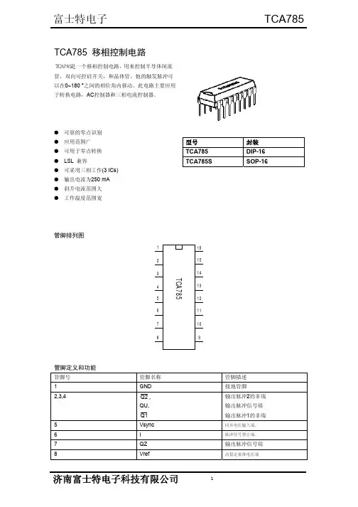
TCA785中文资料TCA785是德国西门子(Siemens)公司开发的第三代晶闸管单片移相触发集成电路,与其它芯片相比,TCA785具有温度适用范围宽,对过零点的识别更加可靠,输出脉冲的整齐度更好,移相范围更宽等优点。
另外,由于它输出脉冲的宽度可手动自由调节,所以适用范围更为广泛。
TCA785的基本引脚波形如图1所示。
其中5脚为外接同步信号端,用于检测交流电压过零点。
10脚为片内产生的同步锯齿波,其斜坡最大及最小值由9、10两脚的外接电阻与电容决定。
通过与11脚的控制电压相比较,在15和14脚可输出同步的脉冲信号,因此,改变11脚的控制电压,就可以实现移相控制,脉冲的宽度则由12脚外接电容值决定[1],当选择双窄脉冲的驱动方式时,12脚应接150pF电容。
实际上,有几十个微秒的脉冲宽度即可使晶闸管正常导通。
3使用TCA785实现相控整流实现三相桥式相控整流的一般方法是利用三相同步变压器从电源进线端引入三路同步信号,这样,将同步信号整形后分别输到三片TCA785(编号为A、B、C)的5脚,就能控制6只晶闸管,然后通过引脚复用即可实现双窄脉冲方式驱动。
双窄脉冲方式由于驱动脉宽窄,因而可以有效地减小驱动用脉冲变压器的体积,防止磁芯饱和[2]。
该方法的主电路及同步变压器如图2所示,三片TCA785芯片的引脚与所控制的晶闸管的对应关系如表1所列。
晶闸管通过一个△/Y型同步变压器为TCA785提供同步信号,当进线相序(如图2所示)为正序A、B、C时,同步变压器的三个输出端所对应的中性点的实际电压向量为AC、BA、CB,将AC接至TCA785(A),BA接至TCA785(B),CB接至TCA785(C),即可实现正序输入时晶闸管的同步驱动。
现以T5~T1换流为例进行分析:T5至T1管自然换流点滞后于A相由负到正过零点30°,即TCA785(A)的15脚输出至少应该滞后于该过零点30°,而电压AC由负到正过零点正好滞后于A相30°,因而用AC作为TCA785(A)的同步信号就可以实现最大范围的移相控制[3]。