MC100监控编辑软件使用手册
- 格式:doc
- 大小:1.82 MB
- 文档页数:17

Mx100 User’sGuideMetLogix Inc175 Canal StreetManchester, NH 03101 USATel: 603.836.4452Fax: 603.369.6499*****************Digital ReadoutUser’s GuideMx100 Digital Readout Software User’s GuidePublished by:Metlogix Incorporated175 Canal Street Suite 503Manchester, NH 03101 USATelephone 603.836.4452Facsimile 603.369.6499*****************User’s Guide part number:16100-00Publishing date: October 29,2019Printed in United States of AmericaCopyright © 2019 by Metlogix, Incorporated, Manchester, New HampshireMx-100 software version: 1.00.00All information set forth in this document, all rights to such information, any and all inventions disclosed herein and any patents that might be granted by employing the materials, methods, techniques or apparatus described herein are the exclusive property of Metlogix, Incorporated., Manchester, New Hampshire.Terms, conditions and features referenced in this document are subject to change without notice.No part of this document may be reproduced, stored in a retrieval system, or transmitted in any form or by any means, electronic, mechanical, photocopying, recording, or otherwise, without prior written permission of Metlogix, Inc. Requests to Metlogix, Inc. for permission should be addressed to the Customer Services Department, Metlogix, Incorporated, 175 Canal Street, Manchester, New Hampshire 03101.Limit of liability and disclaimer of warrantyWhile this guide was prepared with great care, Metlogix makes no representations or warranties with respect to the accuracy or completeness of the contents of this book and specifically disclaims any implied warranties of merchantability or fitness for a particular purpose. The advice, methods and instructions contained in this book might not be suitable for your situation. When in doubt regarding suitability, you are encouraged to consult with a professional where appropriate. Metlogix shall not be liable for any loss of profit or any damages, including but not limited to special, incidental, consequential or other damages.TrademarksMetlogix, is a registered trademark of Metlogix, Incorporated.Android is a registered trademark of the Google Corporation in the United States and other countries.1IntroductionThe Mx100 user guide describes the operation of the Mx100 readout. The Mx100 supports manual part positioning and encoder displacement feedback from a preset or zero position. While this guide might include some material that doesn’t apply to your specific Mx100 configuration, the concepts explained are applicable to all Mx100 systems. For example, Mx100 systems can be 2 or 3 axis systems with X, Y, Z or X, Y axes, however some screens in this document will display one or the other.1.1Mx100 ReadoutThe Mx100 is a metrology readout for applications where precise machine travel in the X, Y, or Z axis needs to be assessed. The Mx100 can be used with optical comparators, measuring microscopes and a variety of other crosshair measurement systems where accurate encoder displacement must be maintained. All user interaction with the software is through the color touchscreen or through the use of softkeys and function keys on the rubberized keypad.Current encoder position can be assessed from a pre-established zero position or by pre-setting the position of an axis to a specific value. X, Y and Z positions can be displayed in Inch or Millimeter units. A Q axis display is also available for Rotary Encoder position output and can be displayed in Decimal Degrees(DD) or in Degrees Minutes Seconds(DMS) format.1.2PrerequisitesOperators are assumed to understand the basics of dimensional metrology.1.3Getting HelpHelp is available:•In this guide.•In the electronic version of this guide accessed from the Help function(“?” Button) in the Mx100 Setup Menu toolbar.•From your MetLogix distributor or system provider.•From our product support page at .If it becomes necessary to contact your MetLogix distributor or system provider, be prepared to supply the following information:•The Mx100 software version number and serial number. These can be read from the main Setup--> “About” page in the Mx100 software.•Information describing the system hardware.• A detailed description of the problem and the steps that you’ve already attempted to resolve it.User Guide ContentsThis user guide is divided into 8 sections:•The User Interface•Zeroing and Presetting the DRO•Sending Data via RS232•User Setup2User InterfaceThe Mx100 Software interface consists of a current position readout, function buttons, and toolbars for performing all zeroing and pre-setting commands, all via a color touchscreen or keypad.2.1ScreensPrimary screens of the software interface are:•DRO Current Position screen(Home screen)•Preset Position screen•Send Result screen(RS232)•Setup screensDRO Current Position Screen contents include:Current Encoder Position displayTop ToolbarBottom Toolbar(softkey functions)2.2Touch Screen – Or not!The Mx-100 features a color touchscreen that can be used to interact with the device. For caustic or harsh operating environments, the touch screen can be locked out and the readout can then be operated entirely by the soft keys and function keys of the rubberized keypad.2.3The Interface RoadmapKeys FunctionNumber Pad Enter numeric digits, decimal points, and sign(+/-)into the current field.Command Keys Enter - Select data entry field or setup menu item.Finish - Confirm selected function or setup menu item. Cancel -Navigate up one level from current setting menu. Quit – Exit the current setting screen back to the top level settings screen.Arrow Keys Navigate the settings menu screens or numeric entry field. The left and right arrows go ina level, or out a level. The up and down arrows move the current selection up/down. Power Key Single Press to Power On. When On, Single Press for Screen Off, Long Press for Power Off. Soft Keys(1-6) Executes the softkey button commands/selection displayed above the key.DRO Keys Execute X/Y/Z/Q zerroing funciton. Select functions as vertical softkeys.Menu Button Displays or advances the Softkey Menu. Long press to enter Mx100 Setup.Softkey Function Toolbar – A storage tray of commonly used functions. The default configuration displays an “Mx” button(access to Setup), an Inch/Metric Button(to toggle display units), and a Datum indicator(displaying current coordinate system).Softkey Function Toolbar - A storage tray for the soft key functions. See function descriptions below.FunctionButton Icon DescriptionIN/MM Button The IN/MM button toggles the display units between Inch and Millimeter.Ref Frame ButtonThe Ref Frame button toggles the Abs/Inc datum frame.Send Button The Send button initiates the RS232 send function.Cart/Polar Button The Cart/Polar button toggles the positional display formatbetween Cartesian and Polar coordinates.DMS/DD Button The DMS/DD button toggles between Degrees MinutesSeconds and Decimal Degrees mode.Help ButtonThe Help button provide access to the PDF User Guide. Thisbutton can only be added to the bottom toolbar.Setup ButtonThe Setup button navigates to the Mx100 setup screen.3 Zeroing and PresettingCreating a “Datum”, or zero position can an essential part of coordinate metrology. In many cases an inspection routine with the Mx100 requires that the current position on the DRO is set to zero, or to some other position.3.1 Zeroing and Presetting the Stage PositionThe stage position can be zeroed or preset to a value as the reference for a measurement.To zero a stage position:•Step 1: Move the stage to the desired measurement reference position.•Step 2: Press the DRO Zeroing Button(screen or keypad) to zero the stage position for the desired axes.3.2 Presetting the Stage Position to Specific CoordinatesTo preset a stage position:•Step 1: Move the stage to the desired measurement reference position.•Step 2: Long-press any DRO Zeroing Button(screen or keypad) to access the preset screen.•Step 3: Enter the desired preset value for each axis and press “Finish” to complete the preset.3.3 Using Two Zero Positions•Step 1: Zero or preset a stage position that you wish to establish as your initial zero position or preset.•Step 2: Press the datum icon( )in the upper tool bar. The datum indicator will now display ‘2’.•Step 3: Position the stage at a new position and set your secondary zero or preset position.•Step 4: Press the ref frame button to toggle back and forth between the stored stage positions.4.0 Exporting values via RS232The Mx100 can send either the current stage position(XYZQ) out of the RS232 port. The port needs to be properly configured, and the correct cable needs to be used in order to successfully send the data.The “RS232” settings screen contains setup parameters for configuring the general-purpose IO port for on the Mx100 readout for serial data output. The port parameters configured on the Mx100 should match that of the connected device (PC).Note: The general purpose IO port on the Mx100 is used for both serial data transfer and button input. As such the wiring for the connection cable must be specific to the connection modes being used. Please see the signal assignment diagram at the end of this section for reference.RS232 Function DescriptionBaud Rate Configure Baud rate for connection. 110 through 115,200 can be chosen using the appropriate softkey.Parity Configure the correct parity mode for the connection. Even/Odd/No can be selected using the appropriate softkey.Stop Bits Configure the correct number of Stop Bits for the connection. 1 or 2 can be chosen using the appropriate softkey.Send Labels Specifies whether or not the coefficient label will be sent along with the value. Set to Yes or No using the appropriate softkey.Send Units Specifies whether or not the unit type for a given value is sent along with the value. Set to Yes or No using the appropriate softkey.Send Eol(End of Line) Configures the desired character to be sent at the end of an output line. CR(Carriage Return), Line Feed(LF) or CR &LF can be selected using the appropriate softkey. EOL can also be set to None.Field Delimiter Configures the desired field delimiter(separator) to Comma or Tab. Set to desired delimiter using the appropriate softkey.MLX200 9 PinDsub(F) Description Switch Device(Footswitch/Buttons/ETC) RS232 9 Pin Dsub(M)1 TRIG_2_IN SW2 Common NC2 RX_IN 23 TX_OUT 34 TRIG_1_OUT NC5 GND SW1 & SW2 (Normally Open) & EarthGround 56 TRIG_1_IN SW1 Common NC7 TRIG_3_IN NC8 TRIG_2_OUT NC9 TRIG_3_OUT NCTo send measurement data out of the RS232 port.•Step 1: Press the Send button to access the axis position selection screen.•Step 2: Press the desired softkey, or use the touch screen, to choose what to send out of the RS232 port. The selections you make will be displayed in orange to indicate their selection state.•Step 3: Press the green check-mark button in the sofkey toolbar to confirm the selection and transmit the data.5 Additional Readout Settings5.1 Configuring a footswitchThe “Quick Keys” settings screen is where the mapping of Mx100 functions to keypad keys and footswitch buttons can be configured.FootswitchUse the Footswitch quick key page to assign keypad button commands to button #1, button #2, or button #3 of the attached footswitch. To assign a footswitch button to a keypad button;•Step 1: Select the “Footswitch” item from the Quick Keys settings menu.•Step 2: Choose the Footswitch button number you would like to assign.•Step 3: Press the “Assign” softkey.•Step 4: A dialog will be displayed, “Press front panel key to assign.”. Press the keypad key that you would like to assign to this footswitch button.•Step 5: The same procedure can be repeated to configure footswitch button #2, and #3.•Step 6: It is also possible to assign the footswitch buttons directly to DRO Zeroing functions. Just select the desired Zero X, Zero Y softkey for the Footswitch button you wish to assign it to.。

M-100 USER’S MANUALRESEARCH, INNOVATE, CREATE“Whenever I speak about my company I speak with the passion we have. Located in the Paris region of France, I have ensured that Micromega has the best ele-ments of my industrial group at their availability. In an age where music is dematerializing, we are committed to staying at the forefront of technology and growing under our ‘made in France’ banner.The M-one programme, with its incredible audio quality, technical capacity and sleek design represents a major advance in the history of our company. The result of three years of research by our team, we are proud to introduce to you what we believe is the most effective and complete integrated stereo amplifier of its kind.Micromega is synonymous with technological advances, expertise, reliability and sound clarity. All of our products reflect these demands.”Didier HAMDI, CEO MicromegaThe advantages of the M-One amplifier series :• High quality, A/B class amplification• Resonant power supply• Symmetrical design• Asahi Kasei AK4490 DAC converter• Acoustic correction in situ using Room EQ1 and EQ2 (included or as an op-tion)• Binaural processing of the headphone output (included or as an option)• Cover and remote control machined from aluminium block• Android and iOS compatible control app (October 2016)1 - OVERVIEW (4)1.1 Front and top (4)1.2 Back (5)1.3 Sides (ventilation) (6)1.4 Bottom (7)1.5 Infrared remote control (8)2 - CONNECTIONS (9)2.1 Phono input for a vinly turntable (9)2.2 RCA line input (10)2.3 Balanced XLR analogue input (11)2.4 Coaxial digital input (12)2.5 Optical digital input (13)2.6 AES-EBU input (14)2.7 USB input (Type B) (15)2.8 Bluetooth aptX connection (16)2.9 I²S input ..................................................................................................182.10 LAN connection .. (19)2.11 Speaker connections (20)2.12 Connecting headphones (21)2.13 Subwoofer output (22)2.14 Pre-out (23)2.15 Trigger sockets (24)2.16 Mains power supply (25)2.17 Fuse (26)3 - USER GUIDE (27)3.1 Starting up (27)3.2 Choosing your source (28)3.3 Ajusting the balance (29)3.4 A justing sensitivity (30)3.5 Renaming the sources (31)3.6 Updating the M-100 (32)3.7 Updating the network module .................................................... (33)4 - SPECIFICATIONS (34)1.1 Front and topThe M-100 amplifier has two displays so that it can be controlled from any position. The displays will automatically adjust to whichever position the amplifier is in (e.g. flat, attached to wall).There is a headphone socket on the front so that you can listen to your music in complete peace. A “Binaural” process (as an option) allows you to re-create the 3D sound scene through the headphones which is lost in classic stereophonic recordings.On the top of the device are 4 buttons which you can use to adjust the reactions of your amplifier (see section 3.1 for more information).Carefully check that the packaging is intact. If you feel it may have been tampered with or damaged please contact your vendor.Carefully remove your device from the packaging. Store the packaging in a secure, dry place: if you need to return your device to the vendor you will require the original packaging.1. Overview1.2 BACKLine level inputa n a l o gi n p u t s d i g i t a li n pu t s a n a l o gi n p u t s tri g g e rTurntableinput ROOM EQ mic plugBalanced inputCoaxial input AES - EBU inputOptical inputUSB inputI²S inputsLAN input USB update inputLeft binding postPre-outSub-outRight binding postFuseMains power supply Trigger1.3 Sides (ventilation)The M-100 amplifier should be positioned so that it can receive sufficient ventilation. Do not obstruct the air vents on the side of your amplifier. You should leave at least 10cm of space around the air vents.We advise against placing the M-100 inside a closed furniture or space1.4 BottomYou will find a connection guide under your M-100 amplifier which illustrates all of the input and ouput terminals available. Do not try to open the M-100It contains potentiallylife-threatening high voltageTake note that the M-100 has spiked feets. It can harm your furniture. Use the included rubber pads to avoid damage.1.5Infrared remote controlON / OFF MuteChange display sizeAjust volumeInput selector« Bluetooth Connect »- Press and release : pairing will start- Press and hold (for 10 seconds then release) : clear Bluetooth memory2.1 Phono input for a vinyl turntableThe « PHONO » input on the M-100 amplifier is compatible with MM and MC cartridges.You can select the correct cartridge for your turntable using the switch located on the back of the amplifier.• If your turntable has an MM cartridge, you should place the switch in the MM position •If your turntable has an MC cartridge, you should place the switch in the MC positionThere is a ‘GND’ grounding terminal near the Phono plugs so that you can connect the grounding terminal of your record player if necessary.Phono input2. CONNECTIONSMM MC2.2 RCA line inputThe M-100’s « LINE » input can be used to connect any device with RCA analogue output.RCA lineinput2.3 Balanced XLR analogue inputThe M-100’s « BALANCED» input can be used to connect any device with symmetrical analogue output.Balanced XLRanalogue input2.4 Coaxial digital inputThe M-100’s « COAX » input can be used to connect any device with an SPDIF coaxial output.The signal should be a PCM stereo signal up to 32bit/768kHz.Coaxial Digital inputYOUR BLU-RAY OR DVD PLAYER MUST BE CONFIGURED IN PCM ON THE AUDIO OUTPUTOTHERWISE IT COULD PRODUCE AN INTENSE NOISE IN YOUR SPEAKERS AND DAMAGE THEM2.5 Optical digital inputThe M-100’s « OPTO » input can be used to connect any device with a TOSlink digital connection.The signal should be a PCM stereo signal up to 24bit/192kHzOptical digital inputYOUR BLU-RAY OR DVD PLAYER MUST BE CONFIGURED IN PCM ON THE AUDIO OUTPUTOTHERWISE IT COULD PRODUCE AN INTENSE NOISE IN YOUR SPEAKERS AND DAMAGE THEM2.6 AES-EBU InputThe M-100’s « AES » input can be used to connect any device with an AES-EBU connection on XLR. The signal should be a PCM stereo signal up to 32bit/768kHz.AES - EBU input2.7 USB Input (Type B)The M-100’s « USB » input can be used to connect any computer with a USB port.The signal should be a PCM stereo signal up to 32bit/768kHz or DSD/DSD-DoP up to 11.2MHz.A USB driver will be required for any computer using Windows. You can download the driver from the M-One page on the Microme-ga website.For computers using OS X or macOS you will not need an additional driver.USB input2.8 Bluetooth® aptX® connectionThe M-100’s « BT » connection can be used to wirelessly connect smartphones, tablets, computers or MP3 players with Bluetooth®. The Bluetooth® link is compatible with aptX® for the best sound quality. To make this manual easier to read, the term « Smartphone » will be used in this section to mean smartphones, tablets, computers and MP3 players. To connect via Bluetooth® for the first time:• Ensure that the Bluetooth® function on your smartphone is turned on.• Use the remote control to click on the ‘BT’ button.• You should see the « M-ONE » appear on the list of Bluetooth® connections available on your smartphone. To establish a connection select the « M-ONE ».• Launch music on your smartphone.To connect via Bluetooth® with a different smartphone, tablet etc.• Ensure that the Bluetooth® function on your smartphone is turned on.• Use the remote control to click on the ‘BT’ button.• Then press release the « BTC » button on the remote control.• You should see the « M-ONE » appear on the list of Bluetooth® connections available on your smartphone. To establish a connection select the « M-ONE ».• Launch play on your smartphone.The following time you select the BT input :• If the Bluetooth® on your smartphone is turned on, the connection will work automatically once you select the ‘BT’ button on the amplifier using the remote.NB : Bluetooth® is a « point to point » connection. This means that if a tablet is already connected to the amplifier, you will not be able to connect your smartphone at the same time. You will need to disconnect your tablet from the amplifier before connecting your smartphone.2.9 I²S InputThe M-100’s « I²S » inputs are ONLY TO BE USED with future Micromega products.Only for use with MICROMEGA productsI²S input2.10 LAN ConnectionThe M-100 can receive music via its network socket (LAN). In order to do this you must connect an Ethernet cable between your modem/router (Internet box) and the M-ONE.You should use DLNA/UPnP compatible software (e.g. JRiver) on your computer to send music to the M-One.LAN input2.11 Speaker connectionsThe amplifier’s terminal block is compatible with naked cables, banana plugs and fork plugs.Naked cables : reveal approx. 10mm of naked cable. Unscrew the terminal block until there is a gap and insert the cable. Screw the block back into placeBanana plugs : once you have attached the banana plugs to the cable, insert the plug into the centre of the terminal.Fork plugs : once you have attached the fork plugs to the cable, unscrew the terminal block until there is space to insert each fork plug. Screw the block back into placeRight speakerLeft speaker2.12 Connecting headphones at the front of the amplifierYou can connect headphones at the front of the amplifier using a 3.5mm mini-jack. If your headphones have a 6.35mm jack then you will need to use an adapter.Once headphones are connected to the front the speakers are rendered inactive. The headphone and speaker volume controls are separate and memorised independently.This headphone terminal is compatible with the « binaural » process which is available as an option. Micromega has researched HTRF (Head Related Transfer Function) in order to reproduce the original sound scene (in front of you).2.13 Subwoofer outputSortie sub-outYou can connect a Subwoofer to the RCA Sub-Out input. This input has a low pass filter with a limiting frequency of 400 Hz.You should control the cutoff frequency and the volume using the control panel on your subwoofer.2.14 Pre-out line outIf you are using an external power amplifier, please use XLR cables to connect it to the Pre-out terminals. The volume of the Pre-Out terminals is variable and follows the volume indicated on your M-100 amplifier.Pre-out2.15 Trigger socketsTrigger sockets enable the use of the amplifier as part of a home automation system.Trigger IN : Can be used with control voltages from 5 to 12V. The amplifier turns on when this voltage is running through it and off when it isn’t.Trigger OUT : When the amplifier is turned on there are 5V running through the Trigger OUT terminal.TriggerINTriggerOUTUse 3.5 mm mono mini-jack sockets2.16 Mains power supplyMain power supplyWe recommend you connect all of your music sources and speakers before connecting the power e the power cable supplied with your amplifier.Check that the mains supply on the label (packaging or underneath the device)matches the mains supply in situ.2.17 FuseIf you are having electrical problems you may need to change the fuse. Please replace it with an identical fuse to the one originally supplied.Use a flat screwdriver to unscrew the fuse holder.If after changing the fuse, it blows again, please contact your vendor.Fuse3. User Guide3.1 Starting upOnce you have attached all of your music sources, spea-kers and the power supply you can turn it on:• Press and release the red ‘STBY’ button on theremote whilst aiming it at the amplifier.• Press the button on the top left of the amplifier.• Red light will turn off on the productAfter a few seconds you should see the ‘Micromega’logo appear on the displays.To turn off your amplifier, use the same process.ON / Standby3.2 Choosing your sourceUSBAES<OKThe main display (fig. 1) shows which input is active (USB), the volume (20) and any specifications of the input signal (only for digital signals).To change the input source, press on the button at the bottom left.A list of sources will now appear in place of the volume (fig. 2).By using the up and down arrows you can select the desired source and confirm using the « OK » button.If you change your mind and don’t want to change the source, press the top left button ( « < » ) to return to the main display.Fig. 1Fig. 2Point the infrared remote control at the device and use it to select your music source.You can use the buttons at the top of the amplifier to do this if you prefer.USB20192 kHz3.3 Adjusting the balanceUSBBAL<OKFig. 1Fig. 2Adjusting the balance enables you to compensate for any dissymmetry in the two speakers related to your listening position. The volume can be adjusted to be louder on one side than the other (6dB on each side).Adjusting the balance effects all sources.From the main display (fig. 1), press on the button at the bottom left.Scroll through the list until ‘BAL ’ (fig. 2) appears and confirm with ‘OK’A balance screen appears where you can make adjustments. You can confirm any adjustments by selecting ‘OK’ or cancel them using ‘<’.symbolise there is an active balance setting (here to the right)3.4 Adjusting sensitivityFig. 1Fig. 2Adjusting sensitivity enables you to compensate for a signal level difference between your sources (+ or - 6 dB).This adjustment is particular to each input. You should be connected to the source you wish to adjust before starting (in this example we are adjusting the LINE terminal).From the main display (fig. 1), press on the button at the bottom left.Scroll through the list until ‘SENS’ (fig. 2) appears and confirm with ‘OK’A sensitivity screen appears where you can make adjust-ments. You can confirm any adjustments by selecting ‘OK’ or cancel them using ‘<’.SENS<OKsymbolise there is an active sensitivity setting (here, sensitivity is lowered)LINE3.5 Renaming the sources20Fig. 1Fig. 2For certain terminals (AES, OPTO, COAX, LINE, XLR) you can select from a predefined list of names.From the main display (fig. 1), press on the button at the bottom left.Scroll through the list until ‘NAME’ (fig. 2) appears and confirm with ‘OK’Scroll through the list of predefined names and choose the name which you feel suits your source best.You can confirm any adjustments by selecting ‘OK’ or cancel them using ‘<’.NAME<OKLINELINENB: Renaming of all inputs can be done through the Micromega app3.6 Updating the M-100Fig. 1Fig. 2Download the .zip folder which contains updates files on the M-One page of our website: Instructions for updates :- Extract the downloaded .zip on your computer- Copy « M-ONE-Vxx.img » onto a USB key (formatted in FAT)- Turn off your M-100 and disconnect it from the mains. - Insert the USB key 1 into port 1 at the back of the M-100- Reconnect the mains, the update will start (fig.1)- A few moments later, an ‘update completed’ message will appear (fig.2)-Disconnect the mains, take out the USB key and reconnect the mains.Micromega M-one software update USB drive found update file found Update completed.Switch off M-one and remove USB drive.NB : If a update is available, you should update to get the most out of your device.3.7 Updating the network module Download the .zip folder which contains updates files on theM-One page of our website: Instructions for updates :- Extract the downloaded .zip on your computer- On your M-One : go to INFO menu (fig. 1) and take note ofthe IP adress written on the second page (fig. 2)If the IP adress is shown as « 000.000.000.000 », download the mobile application (available on Google Play & App Store). This app will list all the connected devices on your network. You must look the IP adress for « Audio Renderer» or «Micromega M-One». - On your computer : write your IP adress in your browser navigation bar- Follow the instructions to update the network module. Select the « NMR-Vxx.bin » file and validate- The network module may take several minutes before rebootingFig. 1Fig. 2<OKINFO MCU FW 0023Serial number<OKINFO nmrs-eng-efs-v1.11.1.8IP 001 .000 .000 .2034. SpecificationsAmplifier sizeWidth : 430 mm Depth : 350 mmHeight (with spikes) : 56 mmAmplifier weight Net weight : 9 kgGross weight : 10,7 kgPackaging (overbox)Width : 735 mm Depth : 600 mm Height : 150 mmPackaging (box)Width : 685 mm Depth : 542 mm Height : 85 mmPower Consumption Standby : 1W 2 channels -1/8 Pmax under 8 Ohms : 140WRated output power P RMS under 8 Ohms : 2*100W P RMS under 4 Ohms : 2*200WSignal to noise ratio Digital input : 106 dB(A)Balanced analog input : 103 dB(A)Unbalanced analog input : 100 dB(A)Phono MM input : Higher than 75 dB(A)Speaker output residual noise, open inputµV160 : under8OhmsµV200 4: under OhmsOutput impedance @250Hz under 8 Ohms 15mΩ500à Damping factor Sup.Total harmony distorsionTHD, 8 Ohms, 63 Hz : under 0,001% THD, 8 Ohms, 1 kHz : under 0,005% THD, 8 Ohms, 10 kHz : under 0,05% THD, 4 Ohms, 63 Hz : under 0,001% THD, 4 Ohms, 1 kHz : under 0,01% THD, 4 Ohms, 10 kHz : under 0,07%Intermodulation distorsion - SMPTEIMD, from 1W to P NOM, 8 Ohms under 0,01% IMD, from 1W to P NOM, 4 Ohms under 0,02%Intermodulation distorsion - DynamicDIM 30, 50W, 8 Ohms under 0,02% DIM 30, 100W, 4 Ohms under 0,05%Channels separation96dBH z under Crosstalk,1k80dBH z under10kCrosstalk,Analog input sensitivityPhono MM, 47 kOhms 12 mVRMS Phono MC, 110 Ohms 1,2 mVRMSVRMS 1,4 Analogue:VRMS 1,7 :BalancedSub-out outputH z400:frequencyCut-offAUDIS MICROMEGA13-15 rue du 8 Mai 194594470 Boissy-Saint-LégerFRANCE parisFRANCE01.02.03.04.05*********************/micromegahifi。

Safety GuidelinesWarning notices must be observed to ensure personal safety as well as that of others, and to protect the product and the connected equipment. These warning notices are accompanied by a clarification of the level of caution to be observed.Qualified PersonnelThis device/system may only be set up and operated in conjunction with this manual. Qualified personnel are only authorized to install and operate this equipment in accordance with established safety practices and standards.Warning:This product can only function properly and safely if it is correctly transported, stored, installed, set up, operated, and maintained.Note: Always use product in accordance with specifications.This document is available in bound version and inelectronic version. We encourage users to purchase authorized bound manuals, or to viewelectronic versions as designed and authored bySiemens Milltronics Process Instruments Inc. Siemens Milltronics Process Instruments Inc. will not be responsible for the contents of partial or whole reproductions of either bound or electronic versions.While we have verified the contents ofthis manual for agreement with the instrumentation described, variationsremain possible. Thus we cannotguarantee full agreement. The contents of this manual are regularly reviewed and corrections are included in subsequent editions. We welcome all suggestions for improvement. Technical data subject to change.MILLTRONICS®is a registered trademark of Siemens Milltronics Process Instruments Inc. Contact SMPI Technical Publications at the following address:Technical PublicationsSiemens Milltronics Process Instruments Inc.1954 Technology Drive, P.O. Box 4225Peterborough, Ontario, Canada, K9J 7B1Email:************************Table of ContentsME100 Motion Probe: Introduction (2)Principle of operation (2)Specifications (3)Dimensions (4)Installation (5)Interconnection (6)Transient voltage protection (6)ME100 Positioning (7)ME100 Operational features (8)High/Low Alarm (HL) Model – Self Calibration (8)Zero Speed (ZS) Model (8)Applications (9)Bucket Elevators (9)Shafts (10)Belt Conveyors (10)Screw Conveyors (10)7ML19981EX01ME100 Motion Probe – INSTRUCTION MANUAL Page 1ME100 Motion Probe: Introduction Note: Please follow the installation and operating procedures to allow for themaximum accuracy and reliability of your ME100 Motion Probe.The ME100 Motion Probe is a safety device specifically designed to protect equipment that has rotating or reciprocating parts. The ME100 detects a changing magnetic field, typically caused by a ferromagnetic target disrupting the magnetic field of the probe1.The ME100 warns of an increase or decrease of motion by detecting alarm conditions.By detecting the disruption immediately, the ME100 protects equipment from damage or process failure.The ME100 is available in two models. The High/Low alarm version (HL) will detectwhether the speed of the monitored target is within a pre-set alarm band of the calibrated speed. The Zero Speed version (ZS) will alarm if the speed of the monitored target falls below 8 PPM (pulses per minute).Note: Before installing the ME100, ensure that the proposed location is free of anystrong 50/60Hz magnetic field caused by nearby power transformers, heater elements, or large industrial motors. These sources can affect the performance of the MotionProbe. (See note1 below).Principle of operationThe ME100 uses the principle of electromagnetic induction to detect the displacement ofa ferromagnetic object.The probe generates a magnetic field. When this magnetic field is disrupted by a moving ferromagnetic object, such as the bucket of a bucket elevator, the flight of a screwconveyor, or the keyway on a shaft, the coil of the probe generates voltage. This voltage is directly proportional to the strength of the field of the coil, the number of wire turns in the coil, and the speed of the ferromagnetic object. It is inversely proportional to the fourth power of the distance between the object and the coil.The voltage signal is conditioned to generate pulses for subsequent digital signalprocessing.1.Extremely strong magnetic fields (such as those produced by the 30A/mrequirements of IEC 61000-4-8 Power Frequency Magnetic Field Immunity Test)will be detected by the ME100. This will result in a loss of functionality whichmay cause the ME100 to falsely indicate alarm conditions by relay trip and/or achange in the color/state of the indicator LED.Page 2ME100 Motion Probe – INSTRUCTION MANUAL7ML19981EX01SpecificationsPower•24 Vdc (20–30 Vdc), 0.030 Adc maxOutput• 1 form C (S.P.D.T.) dry relay contact•Rated 1A at 50 VdcOperating RangeHigh/Low alarm (HL)•Standard: 2 to 480 PPM for rotating pulley, bucket elevators, drive sprockets•Optional: 0.5 to120 RPM for screw conveyor applications; 8 to1920 PPM (pulses perminute) for motor shaftsZero Speed (ZS)•8 to 1920 PPM, under-speed alarming below 8 PPMAlarm Band(HL version only)•Standard: ± 12% of calibrated 100% speed•Optional:± 3%, ± 6%, ± 25%, ± 50%Note: ± 50% offers under-speed alarming onlyProbe Sensitivity•Minimum distance 38 mm (1.5”) @ 0.6 m/min (2 ft/min) speed,with a target 50 mm (2") x 25 mm (1") and 25 mm (1") thickor•Minimum distance 76 mm (3”) @ 2.1 m/min (7 ft/min) speed,with a target 50 mm (2") x 25 mm (1") and 25 mm (1") thickOperating Temperature• –20 to +65o C (–4 to 149o F)• 5% to 95% Relative Humidity, No CondensationConstruction•Potted housing 316 stainless steel•Cable: 3m, 6 conductor, 22 AWG, shieldedIngress Protection•IP65Approvals•CE7ML19981EX01ME100 Motion Probe – INSTRUCTION MANUAL Page 3DimensionsME100 Motion Probe Dimensions (mm)Mounting Bracket Dimensions (mm)Page 4ME100 Motion Probe – INSTRUCTION MANUAL7ML19981EX01InstallationThe ME100 must be mounted in a non-hazardous area that is within the ambienttemperature range and is non-corrosive to the materials of construction (stainless steel enclosure and conduit).Note:•Use the bracket supplied to mount the ME100 onto a vibration-free structure.The gap between the probe and the target should be sufficient to prevent thetarget damaging the probe. If the target is enclosed by mild steel, a stainlesssteel “window” can be fabricated, to allow the sensor to read the target.•Use flexible conduit to connect the ME100, to make it easier to remove or adjust.7ML19981EX01ME100 Motion Probe – INSTRUCTION MANUAL Page 5Page 6ME100 Motion Probe – INSTRUCTION MANUAL 7ML19981EX01InterconnectionTransient voltage protectionThe input power supply lines of the ME100 are equipped with overvoltage protection circuitry. This circuitry protects the system from lightning, line transient and high voltage spikes, and provides a high degree of safety.Use a fuse to protect the relay contacts from excessive current flow.Cable Color Designation ColorFunction black- power supply negative red + power supply positivewhite relay commonblue relay normally open 1greenrelay normally closed 1orange shield/case ground 1.Relay energized: non-alarm stateME100 PositioningYou must be able to interrupt the 24 Vdc power supply to the ME100. If an ME100 N.O.relay contact is tied into the equipment control scheme, jumper the contact to allow the equipment to run.Locate the ME100 probe as shown in one of the application diagrams, and hand tighten the nuts and bolts which secure the clamping bracket. Ensure that any equipment guards are in place, then follow steps 1 to 6.1.Start up the equipment and run at desired speed2.Apply power to the ME100. The LED on the non-target end of the probe should pulsegreen, as each target passes by.3.If, instead of pulsing green, the LED illuminates red, shut down the equipment,interrupt power to the ME100 and re-position the probe target end closer to thetargets.4.Repeat step s 1, 2 and 3 until there is a green pulse for each target that passes by theprobe.The best position for the ME100 will be close enough to ensure high confidence inreading the targets, but far enough away to prevent the target, or any othertravelling components, from striking the ME100.5.Tighten the clamping bolts with wrenches to fully secure the ME1006.Remove power from the ME100, remove any contact jumpers and finalize wiring.The ME100 will now be ready to run when it is powered up again. We recommend that you apply power to the ME100 at the same time as, or after, you apply power to theequipment being monitored.Note:•The ME100 can be applied with the conduit nipple in any position, so long as the length of the probe is perpendicular to the targets.•Ensure the probe is mounted to a relatively vibration-free structure. High amplitude vibration may cause false pulses due the reaction of the probe to the Earth’smagnetic field.7ML19981EX01ME100 Motion Probe – INSTRUCTION MANUAL Page 7ME100 Operational featuresHigh/Low Alarm (HL) Model – Self Calibration Once the ME100–HL is powered, the alarm relay is energized, and the ME100 waits for the moving object to reach its nominal speed. There is a four-second delay, after which the first two pulses calibrate the system and the third verifies the calibration frequency.The ME100–HL is then armed and ready to detect and monitor motion variations.If the ME100–HL is unarmed and no motion is detected within a pre-set time limit (60 seconds divided by the minimum pulse rate of the model), or if the acknowledgement fails to confirm the speed, the alarm is activated and the relay de-energizes.Once armed, the ME100–HL continuously monitors the presence of incoming pulseswithin a pre-set tolerance, depending on the alarm band option. (±12% is standard.)The ME100–HL has two operating states indicated by a two color LED:•Normal: a green pulse on the LED indicates that the target has been detected,and that the pulse rate indicates proper operation•Alarm: a solid red LED indicates that the speed of the monitored target iswithin the alarm band of the calibrated speedThe alarm relay will re-energize if the speed of the monitored target returns to within the pre-set tolerance of the calibrated set point.Zero Speed (ZS) ModelOnce powered, the ME100–ZS energizes the alarm relay, which remains energized for a start up delay of 4 seconds, to allow the process to reach operating speed. If a pulse rate greater than 8 PPM is detected the relay remains energized, and the ME100–ZS is armed and ready to detect and monitor motion variations.The ME100–ZS has two operating states indicated by a two color LED:•Normal: a green pulse on the LED indicates that the target has been detected,and that the pulse rate indicates proper operation•Alarm: a solid red LED indicates that the pulse rate has dropped below the 8 PPM default setting, indicating loss of speedOnce the pulse rate exceeds the 8 PPM default setting, the alarm relay is re-energized, indicating proper operation.Page 8ME100 Motion Probe – INSTRUCTION MANUAL7ML19981EX01ApplicationsThe ME100 detects a target such as the bucket of a bucket elevator, the flight of a screw conveyor, or the keyway on a shaft. If the target is hard to distinguish, for example, a fine flight, or a shaft without a keyway, a ferrous mass can be added to provide a clear target. Bucket Elevators1.For Belt-Driven Elevators with ferrousbuckets spaced at intervals greater than76mm (3"), or non-ferrous buckets withferrous bolts, locate the ME100 on theback of the down leg.2.For ferrous buckets spaced at intervalsless than 76mm (3"), locate the ME100on the front of the down leg.3.For Chain and Sprocket Drive Elevators,locate the ME100 so that the gapbetween the bucket and the sensor enddoes not exceed 102mm (4"). To preventdamage to the ME100 from eccentricbucket motion, ensure that the gap is notless than 12.5mm (0.5") in the worstconditions.4.For elevators with ferrous walls, cut aME100(See detail A)Down LegPage 10ME100 Motion Probe – INSTRUCTION MANUAL 7ML19981EX01ShaftsA keyway or paddle blades may be used as a target when the shaft speed is sufficient for the blades or key to provide the number of pulses required at a minimum velocity of1.5m/minute (5ft/minute). In applications where exposed moving parts cannot be avoided, take precautions, and provide safety shields.Belt ConveyorsLocate the ME100 so that the gap from the sensor end to the target is a maximum of 102mm (4"). The optimum distance is 25 mm to 51mm (1" to 2"). The potential for damage in each application governs the minimum gap allowable.Screw ConveyorsIf the target is difficult to detect, (for instance if the flight is very fine), you can add a ferrous mass behind the flight of the screw conveyor where it passes the ME100, to improve detection in borderline conditions. This mass must be added for all non-ferrous screws.by the arrows.11 for details.)Non-Ferrous Window:For Screw Conveyors with a trough over 3.2 mm (0.13") thick152 mm (6") square openingThe dimensions shown for the base, window and bracket are the minimumrecommended, with tolerances of ±0.8 mm (0.031"). Use 305, 310, or 316 Stainless Steel, Brass, or Aluminum.The ME100 may not touch the window if temperatures are in excess of 65o C (150o F).7ML19981EX01ME100 Motion Probe – INSTRUCTION MANUAL Page 11NOTESPage 12ME100 Motion Probe – INSTRUCTION MANUAL7ML19981EX01。

XJ-MC100智能马达控制器说明书XJ-MC100系列是我公司推出的全系列低压智能配电产品,该系列产品是针对发电厂开发和生产的新一代智能化、网络化、数字化的低压马达保护控制器。
该控制器采用模块化的设计结构,在全面实现保护、测量、操作、控制一体化的同时,将先进的网络通讯技术和分布式智能技术融入MCC控制中心里,为工业生产过程控制提供了科学有效的现场级保护及测控装置。
该控制器与接触器、软启动器、塑壳断路器、框架断路器配合为低压交流电动机回路提供了一整套集控制、保护、检测和总线通讯于一体的专业化解决方案,取代了热继电器、热保护器、漏电保护器、欠压保护器及多种分列保护器,取消了时间继电器、中间继电器、辅助继电器、电流互感器、仪表、控制和选择开关、指示灯、可编程控制器及变送器等多种附加元件,是智能化MCC和PC的理想选择。
产品特点◆采用高性能的工业级微处理器,集全面的电动机数字保护、现场/远方启停操作控制、三相综合电量测量及电能计量、运行状态监视、远方参数设置、保护动作记录(可以记录最近8次电动机保护动作原因、性质及动作时间)及网络通讯与一体;◆加强型单元机箱按抗强振动和强干扰设计,适用于比较恶劣的环境,可安装在MNS、GCS、GCK、GGD等各种抽出式、固定式及混合式的柜体中;◆保护控制单元与多功能显示操作单元(72*72*35mm)采用分体安装结构,安装/维护极为灵活便利,在减少布线量的同时,可最理想的使用开关柜空间;◆保护功能:具有堵转、过载、欠载、电流不平衡、接地、漏电、缺相、过压及反时限过负荷等多种数字式综合保护功能,仅需简单选择即可实现保护的投入或退出、报警或跳闸,保证MCC系统安全可靠的运行;◆满足直接启动、双向启动、双速启动、星/角启动、自耦变压器等多种启动方式,简化控制回路的接线,提高运行的可靠性;◆标配8路开关量信号输入(可根据用户需要扩展),用于本地起停信号、复位信号及接触器状态等信号的输入,实现远方主站对电动机运行状态的监视;◆先进的综合电量测量功能,可对电动机回路的三相电压、电流、功率因数、有功功率、无功功率等20多种电参数的测量和有功电能及无功电能的计量;◆具有独立的保护跳闸或报警输出接口及1路标准的DC4-20mA模拟量输出接口(选配,多种电量可选),为DCS系统对现场设备监控提供了极大的便利;◆具有1路标准的RS-485通讯接口/Modbus RTU通讯协议,组网经济、方便;◆可完全替代各种指针式电量表、信号灯、热继电器、电量变送器等常规电器元件,减少柜内线缆及现场布线的施工量;第一章技术指标1.1额定数据电动机额定电压:交流380V或660V,直接接入XJ-MC100控制器;电动机额定电流:XJ-MC100内部含小型CT,CT一次侧输入电机额定电流可为交流:0.5A~2A(2A),1.6A~6.3A(6.3A),6.3A~25A(25A),25A~100A(100A);控制器电源电压:AC/DC 85~265V;开关量输入:采用内部DC24V电源;继电器输出:AC250V/10A;DC30V /5A;注:1、电动机额定电流在100A以下时,用户需要根据使用电动机的额定电流选择相应电流型号的控制器。

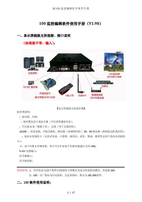
100监控编辑软件使用手册(V1.98)一、显示屏超级主控连接、接口说明(标准版不带、输入):【显示屏超级主控拓扑图】拓扑图说明::接功放、音响;:接外置发送卡或显示器(可以查看播放内容);:可以接U盘(数据上传)、无线(用于无线控制);10/100 :直连电脑,可接交换机、路由器(局域网控制)、3G、4G路由器(跨网段远距离控制);:接显示屏接收卡(支持灵星雨、卡莱特、德普达、诺瓦、聚诚、德利等支持千兆技术的接收卡);卡:盒子内置2存储容量,加卡可以扩容盒子存储容量(最大支持256);5-12V电源输入;信号源输入;信号源切换;特别说明:1、先用发送卡(或千兆网卡)将接收卡参数以及显示屏连接设置好,再连接100;2、100,出厂地址为自动获取,无法获取时,默认为192.168.0.77。
二、100软件使用说明:1、软件的下载和安装:官网()下载100监控编辑软件(以下简称100软件),下载后运行100编辑监控软件安装文件。
安装后桌面会有个的图标,双击即可运行。
2、100软件主界面按钮说明:(100软件初始界面)3、大屏幕参数设置3.1)点击管理中的一键连接播放盒或直接点击进入快速连接播放盒(如下图所示);3.2)点击”开始连接”,进入下图所示点击”设置屏幕参数”,输入密码“168”,进入屏幕设置:3.2.1)基本设置(如下图所示),输入名称、大小,点击”上传设置”(基本设置界面)3.2.2)有线网络设置(如下图所示),如选择”屏幕自动获取”则显示屏超级主控在每次重新启动都会由网络路由器自动分配,建议选择使用固定,输入固定和网关后点击”上传设置”即可修改显示屏超级主控的地址。
(有线网络设置界面)3.2.3)无线设置(如下图所示),此设置需要连接无线模块,在窗口中输入相应的名称、加密方式、入网密码后点击上传设置即可。
(无线设置界面)3.2.4)自动连接(如下图所示),如果在局域网内,可选择”通过本机自动连接”广域网内,可以选择”通过入网证书连接”说明:选择远程连接则需要在监控的电脑上传相同的入网证书,才能通过远程设置进行统一管理屏幕,可以在”监控中心”的在线状况中等待在线的显示屏超级主控(大约80秒左右的扫描时间)。
Manual del operador Detector de humedad Model MO100IntroducciónFelicitaciones por su compra del detector de humead modelo MO100 de Extech. Las lecturas se toman insertando las agujas en el material que se quiere medir. El uso cuidadoso de este medidor le proveerá muchos años de servicio confiable.Precauciones•Este dispositivo no es un juguete y no debe llegar a manos de los niños. Contiene objetos peligrosos así como partes pequeñas que losniños podrían tragar. En caso de que algún niño trague cualquier parte, por favor llame al médico inmediatamente•No deje las baterías y material de empaque sin atención; ya que pueden ser peligrosos para los niños si los usan como juguetes •En caso de que no use el dispositivo durante largo tiempo, retire las baterías para prevenir derrames•Las baterías vencidas o dañadas pueden causar quemaduras al contacto con la piel. Por lo tanto, use siempre guantes apropiados para tales casos•Revise que las baterías no estén en corto. No deseche las baterías en el fuego.EspecificacionesIndicador Dos pantallas LCD Humedad deoperación90% Humedad relativa (max.)Escala del indicador de humedad 0 a 100 Fuente detensión2 baterías AAAEscala de temperatura 0°C a 50°C (32°F a122°F )Dimensiones 192 x 30 x 45 mm (7.6 x 0.8 x1.8")°C/ °F Resolución 0.2° Peso108g (3.8oz)D escripción1. Agujas2. Sensor de Temperatura3. Cabaza Giratorla Boton4. Indicador5. CAL Adjusta6. Off/Test/Cal7. Asimiento8. °C/ °F9. Indicador de Temperatura10. BatteriasUnidades de temperaturaEste medidor indica la temperatura ambiente. Las lecturas pueden mostrarse en °F o °C. Use el selector ubicado atrás del medidor para seleccionar la unidad de medida apropiada..Reemplazo de la bateríaUsted, como usuario final, está legalmente obligado (Reglamentode baterías) a regresar todas las baterías y acumuladores usados;¡el desecho en el desperdicio o basura de la casa está prohibido!Usted puede entregar las baterías o acumuladores usados,gratuitamente, en los puntos de recolección de nuestrassucursales en su comunidad o donde sea que se venden lasbaterías o acumuladores.DesechoCumpla las estipulaciones legales vigentes respecto al desechodel dispositivo al final de su vida útil.Antes de usar, calibre el instrumento usando los siguientes pasos.1. Resbale el interruptor Off/Test/Cal a la posición CAL.2. Gire la perilla de ajuste CAL hasta que la pantalla indique 100. (Estese hace para fijar un punto de referencia.)Nota: (La perilla de ajuste CAL está embutida para prevenircambios accidentales. Use un objeto con el extremoahusado para hacer ajustes.)3. Deslice el interruptor Off/Test/Cal a la posición TEST4. El medidor está listo para tomar lecturasToma de lecturasSe usa el siguiente procedimiento para tomar lecturas relativas o comparativas del contenido de humedad en madera, tablaroca y otros materiales. Laslecturas obtenidas son indicaciones relativas del nivel de humedad NO del %de contenido de humedad.1. Resbale el interruptor Off/Test/Cal a la posición Test.2. Para establecer una referencia para el material a prueba inserte lasagujas del sensor en un área seca (o aceptable) del material. Lainserción deberá ser lo más profundo posible. Note la lectura "seca"3. Entonces inserte las agujas del sensor en un área húmeda delmaterial a prueba. La inserción deberá ser lo más profundo posible.Note la lectura "húmeda".4. Use estas lecturas sea a húmeda como puntos de referencia como puntode comparación para las lecturas siguientes.Las lecturas seca y húmeda de algunos materiales comunesTablaroca MaderaIndicación Valor de humedad Indicación Valor de humedad 0-5 Seco 0 a 8 Seco6-14 Húmedo 9-22 Húmedo>14 Mojado >22 MojadoConversión de lecturas relativas a % de contenido de humedad Las lecturas obtenidas son indicaciones relativas del nivel de humedad NO del% de contenido de humedad. Por favor consulte la tabla para una conversión aproximada de lecturas relativas al % de contenido de humedad.Reemplazo de agujasPara su conveniencia, el medidor usa agujas roscadas. Para remplazar una aguja, simplemente desenrosque del medidor y tenga cuidado de no apretar demasiado la aguja nueva.Nota de seguridad:Para su seguridad, el MO100 tiene una cabezagiratoria con botón para soltar el candado. Por favor recuerde girar lacabeza de manera que las agujas queden ocultas dentro delcompartimiento.Copyright © 2012 Extech Instruments Corporation (a FLIR company) Reservados todos los derechos, incluyendo el derecho de reproducción total o parcial en cualquiermedio.MO100-EU-SP-V3.4-2/12Escala de conversión para madera (Aprox)REL 2 4 8 16 22 30 38 44 62 68 72 76 78 83%MC 16 17 18 19 20 21 22 23 24 25 26 27 28 29。
Package‘mcStats’October13,2022Title Visualize Results of Statistical Hypothesis TestsVersion0.1.2Maintainer Michael Czekanski<*************************>Description Provides functionality to produce graphs of sampling distributions of test statis-tics from a variety of common statistical tests.With only a few keystrokes,the user can con-duct a hypothesis test and visualize the test statistic and corresponding p-value through the shad-ing of its sampling distribution.Initially created for statistics at Middlebury College. Depends R(>=3.4.0)License GPL-3Encoding UTF-8LazyData trueRoxygenNote7.0.2Imports dplyr,ggplot2,ggthemes,gridExtra,magrittr,rlang,stats,tidyrSuggests testthatNeedsCompilation noAuthor Michael Czekanski[aut,cre],Alex Lyford[aut]Repository CRANDate/Publication2020-02-2606:50:02UTCR topics documented:bootstrap (2)hello (3)labelBootResults (3)labelPDFDis (4)mcDChiSq (4)mcDF (5)mcDNorm (5)mcDT (6)12bootstrapshadePDFCts (6)showANOV A (7)showChiSq.Test (7)showMcNemarTest (8)showMosaicPlot (9)showOLS (9)showProp.Test (10)showT.Test (10)showXtremeEventsCts (11)showXtremeEventsDis (12)Index13 bootstrap BoostrapDescriptionBoostrap using given data and statisticUsagebootstrap(fun,data,h0,nreps,conf.level=0.95,verbose=1)Argumentsfun function to calculate on each sample.This can be a user-defined function that takes in data as a vector and returns a statistic.data data to use for bootstrapping.Should be a respresentative sampleh0null hypothesis valuenreps number of times to bootstrapconf.level confidence valueverbose default is1which will create a graph.To turn this off use verbose=0.Valueresults from boostrapping.A vector of length@param nreps containing each statistic calculatedExamplesx<-rnorm(100)bootstrap(mean,x,0.5,1000,verbose=0)bootstrap(mean,x,0.5,1000)hello3 hello Print"hello world!"Descriptionprint"hello world!"Usagehello()Exampleshello()labelBootResults Label Bootstrapped ResultsDescriptionlabels bootstrapped results.We use this to create colored histograms.UsagelabelBootResults(results,lBound,uBound)Argumentsresults a vector,data from bootstrappinglBound lower bound of confidence intervaluBound upper bound of confidence intervalValuevector of labels corresponding to result valuesExamplesx<-rnorm(100)labelBootResults(x,-1,1)4mcDChiSq labelPDFDis Label discrete PDFDescriptionlabels a discrete pdfUsagelabelPDFDis(x,obsVal,expVal)Argumentsx x valueobsVal observed eventexpVal expected valueValuevector of labels for x value in relation to observed eventExampleslabelPDFDis(0:10,3,5)mcDChiSq Density of Chi-Square distributionDescriptionDensity of Chi-Square distributionUsagemcDChiSq(x,degFree,...)Argumentsx x valuedegFree degrees of freedom...optional additional parameters which are ignoredValuedensity of given Chi-Square dist.at xmcDF5 mcDF Density of F-distributionDescriptionDensity of F-distributionUsagemcDF(x,degFree1,degFree2,...)Argumentsx x valuedegFree1degrees of freedom1degFree2degrees of freedom2...optional additional parameters which are ignoredValuedensity of given F-dist.at xmcDNorm dnorm but with more argumentsDescriptioncompute density of normal distribution while allowing for more arguments which are ignored UsagemcDNorm(x,mean=0,sd=1,log=FALSE,...)Argumentsx x valuemean mean of normal distributionsd std.dev.of noraml distributionlog logical;if TRUE probabilities are given as log(p).See stats::dnorm...extra parameters which are ignoredValuedensity of normal distribution6shadePDFCts mcDT Density of t-distributionDescriptionDensity of t-distributionUsagemcDT(x,degFree,...)Argumentsx x valuedegFree degrees of freedom...optional additional parameters which are ignoredValuedensity of given t-dist.at xshadePDFCts Used to shade in a PDFDescriptionReturns density with extreme event region having NAsUsageshadePDFCts(x,fun,testStat,...)Argumentsx x valuefun density function to usetestStat test statistic value...optional parameters passed to density functionValuedensity if outside of extreme event regionshowANOV A7 showANOVA Show results of ANOVADescriptionVisualization of distributional results of ANOV A.Please see aov for more information on parame-tersUsageshowANOVA(formula,data=NULL,verbose=1,...)Argumentsformula formula specifying a model.data data on which to perform ANOV Averbose if verbose>0the resulting graph is printed...Arguments passed to lm.See aov for more detailValueoutput of call to aovExamplesshowANOVA(yield~N+P+K,npk)showChiSq.Test Show Chi-Square TestDescriptionshow results of a chi-square test visually using chisq.testUsageshowChiSq.Test(x,y=NULL,p=rep(1/length(x),length(x)),simulate.p.value=FALSE,nreps=2000,verbose=1)8showMcNemarTest Argumentsx a numeric vector or matrix.x and can also be factorsy a numeric vectorp a vector of proabilities the same length as ed for goodness-of-fit tests.Must be a valid distributionsimulate.p.valueboolean,if TRUE use simulation to estimate p-valuenreps if simulate.p.value=TRUE number of simulations to completeverbose level of visual output,0=silentValueresults of chisq.test callExamplesshowChiSq.Test(x=c(1,2,1),y=c(1,2,2))showMcNemarTest Visualize results of McNemar’s TestDescriptionrelevant parameters are passed to mcnemar.testUsageshowMcNemarTest(x,y=NULL,correct=TRUE,verbose=1)Argumentsx two dimensional contingency table as a matrix or a factor objecty factor object,ignored if x is a matrixcorrect logical indicating whether or not to perform continuity correctionverbose if verbose>0the resulting graph is printedValueresults of call to mcnemar.testshowMosaicPlot9 showMosaicPlot Mosaic PlotDescriptionMosaic PlotUsageshowMosaicPlot(x)Argumentsx must be a matrix with each row and column labelledValuemosaic plot showing observed proportions,colored by residuals from chi-sq.testExamplesx<-matrix(runif(9,5,100),ncol=3,dimnames=list(c("Yes1","No1","Maybe1"),c("Yes2","No2","Maybe2")))showMosaicPlot(x)showOLS Show hypothesis tests from OLSDescriptionShow hypothesis tests from OLSUsageshowOLS(formula,data,verbose=1)Argumentsformula forumula for regression.Passed to lmdata data for regression.Passed to lmverbose if verbose>0the resulting graph is printedValuemodel object resulting from the regression10showT.TestExamplesshowOLS(mpg~cyl+disp,mtcars)showProp.Test Show results of proportion test using binom.testDescriptionShow results of proportion test using binom.testUsageshowProp.Test(x,n,p=0.5)Argumentsx x valuen number of repetitionsp probability of success in one Bernoulli trialValueoutput of call to binom.testExamplesshowProp.Test(3,10)showT.Test Conduct z-testDescriptionRuns z-test and outputs graph for interpretation using stats::t.testUsageshowT.Test(group1,group2=NULL,mu=0,paired=FALSE,verbose=1) Argumentsgroup1continuous data to testgroup2optional:second group to include for two sample t-testmu optional:mean to test against for one-sample t-testpaired boolean,if TRUE perform matched pairs t-testverbose default is1which will create a graph.To turn this off use verbose=0.Valueresults of call to t.testExamplesx<-rnorm(100)showT.Test(x,verbose=0)showT.Test(x)showXtremeEventsCts Highlight extreme eventsDescriptionMake graph highlighting events more extreme than observed sampleUsageshowXtremeEventsCts(testID,testStat,densFun,degFree=NULL,degFree1=NULL,degFree2=NULL,xlims,verbose=1,...)ArgumentstestID name of hypothesis testtestStat test statisticdensFun function that computes appropriate densitydegFree degrees of freedom when only one is needed.This gets passed into densFun degFree1first degrees of freedom parameter when more than one is neededdegFree2second degrees of freedom parameter when more than one is neededxlims x limits of the graph to be used.This is passed to ggplotverbose if verbose>0the resulting graph is printed...extra arguments passed to density functionValueresults of call testFunExamplesx<-rnorm(100)showT.Test(x,verbose=0)showT.Test(x)showXtremeEventsDis Show Extreme Events from a Discrete DistributionDescriptionShow Extreme Events from a Discrete DistributionUsageshowXtremeEventsDis(testID,obsVal,expVal,xVals,probFun,...)ArgumentstestID name of test being performed.This is used to title the graphobsVal observed x valueexpVal expected x valuexVals domain of x(possible values)probFun probability mass function for the given distribution...addition arguments passed to probFunValuegraph coloring events by how extreme they are under the null hypothesisExamplesshowXtremeEventsDis("Prop.Test",3,5,0:10,probFun=dbinom,size=10,prob=0.5)Indexaov,7binom.test,10bootstrap,2chisq.test,7,8hello,3labelBootResults,3labelPDFDis,4lm,9mcDChiSq,4mcDF,5mcDNorm,5mcDT,6mcnemar.test,8shadePDFCts,6showANOVA,7showChiSq.Test,7showMcNemarTest,8showMosaicPlot,9showOLS,9showProp.Test,10showT.Test,10showXtremeEventsCts,11 showXtremeEventsDis,1213。
MC100系列智能多媒体控制系统Intelligent Multimedia Control System(适用于MC100系列机型)用户安装手册User’s Manual* *请在安装使用前认真阅读本说明书**尊敬的用户:感谢您选购我们生产的这个系列多媒体中央控制器。
该产品具有外观设计小巧高档大方;使用简单方便;功能强大;可直接外接其他厂家的设备;二个可编程232口最多可同时控制两个不同厂家的投影机或其他设备;可对各接口重新定义和单独控制;投影机一键切换;投影幕自动升降;开机即是电脑画面等等多种实用功能。
为了您能安全地使用本设备,发挥其最大的功能,强烈建议在安装使用前先仔细阅读本说明书。
若有任何技术问题或对产品的意见和建议,请与本公司技术服务部联系。
联系方法如下:电话:(020)33534881 61087188传真:(020)61087188-8002地址:广州市天河软件园建工路9号4楼南区A1邮编:510665E-mail:laitong@http://特别提醒:1. 在使用本系统的时候,严禁在开机时对各个部件进行插拔(特别是通讯口及VGA接口,这可能会人为损坏设备)。
2. 本控制器为智能开关设计,在雷雨天气或长时间不使用时,请关闭电源总闸。
3. 本控制器内有强电模块,严禁带电自行维修。
4.因中控本身已做好接地处理,为有效保护中控及设备,请在强电输入部分做好接地措施!目录一.系统说明1,中控简介 (5)2,简单使用说明 (5)二,硬件连接1,连线说明 (6)三,系统设置1,系统通讯协议 (8)2,开机状态设置 (10)3,开关机流程设置 (11)4,开关延时设置 (12)5,投影机设置 (12)6,红外学习 (14)7,按键面板设置 (15)8,其它设置 (16)四,常见故障处理1,按控制面板“系统开”无法开机 (18)2,红外学习不成功或显示成功却不能遥控 (18)3,有些设备红外遥控不灵 (19)4,投影机打不开 (19)5,中控与电脑连接失败 (19)一、系统说明1. 中控简介智能多媒体控制器为简单电化教室、会议室及家居提供了很好的解决方案。
Safety Manual for Sendyne SIM100MOD Isolation MonitorThis document describes how to use the Sendyne SIM100MOD isolation monitor in a safety related system. ContentsSafety Manual for Sendyne SIM100MOD Isolation Monitor 1Introduction (2)Sendyne SIM100MOD overview (2)Safety functions and diagnostics overview (3)Target applications (4)Assumptions (6)Custom development (6)Safety documentation (6)Audits and certification (6)Device operating states (6)Product lifecycle support (7)Appendix (8)Proper connection to the target system (8)Revision history (10)List of figuresFigure 1: SIM100MOD functional diagram (3)Figure 2: The boundary diagram of SIM100MOD as SEooC in EV implementations (4)Figure 3: The boundary diagram of SIM100MOD as SEooC in EV implementations (5)Figure 4: Operating states of the SIM100MOD (7)Figure 5: Proper connection to IT power system terminals (8)Figure 6: Proper connection at two distinct point to the chassis (8)Figure 7: Presence of Y-capacitors is a requirement for proper function of the SIM100MOD. (9)IntroductionThe system and equipment manufacturer or designer intending to use this product is responsible to ensure that their system incorporating Sendyne’s SIM100MOD meet all applicable safety, regulatory and system level performance requirements. All information presented in this document is for reference only. Users understand and agree that their use of SIM100MOD in safety-critical applications is entirely at their risk, and that user (as buyer) agrees to defend, indemnify, and hold harmless Sendyne from any and all damages, claims, suits, or expense resulting from such use.This safety manual provides information to assist system developers in creating safety-related systems incorporating the Sendyne SIM100MOD isolation monitoring device. This document contains:•Overview of the SIM100MOD architecture•Overview of the safety architecture for management of hardware failures•Assumptions of UseSendyne assumes that the user of this document has a general familiarity of the SIM100MOD. This document is intended to be used in conjunction with the relevant datasheet and application notes.Sendyne SIM100MOD overviewThe SIM100MOD is an electrically isolated device that when connected properly to an idle or active high voltage IT power system (floating ground) can estimate the resistive and capacitive paths between each power rail of the IT system and a third reference point. The SIM100MOD can communicate through CAN bus (250 or 500 kbits/s) and when interrogated by a host it can provide estimates on the values of each resistive and capacitive path.The SIM100MOD, based on information programmed by the host for the designed maximum voltage of the IT power system, will calculate a value for the minimum resistance path between the two IT power system rails and the third voltage reference point, expressed in Ohms/Volt (max designed voltage). In addition, it will estimate the total energy that can be potentially stored in the IT power system capacitances. If the CAN bus host fails to provide information on the maximum IT power system voltage, the SIM100MOD will calculate these values based on the maximum voltage observed during its operation.The SIM100MOD power input accepts any supply voltage between 4.8 V and 53 V. The input voltage is pre-regulated and then stepped down through a DC/DC converter feeding through galvanically isolated inputs the +5 V IC supply and the 12.5 V excitation voltage source supply.The SIM100MOD safety architecture includes a watchdog timer, CRC check on internal non-volatile program memory, diagnostics for proper connections of chassis and IT power system terminals, monitoring of the unregulated power supply voltage level for the main IC before local voltage regulator (LDO), environment temperature monitoring and excitation pulse voltage monitoring. In addition, theSIM100MOD safety architecture monitors the voltage divider values for chassis, positive and negative voltage connections and provides a visual heartbeat signal indicating proper IC operation.All estimates of isolation resistances and capacitances are submitted along with an uncertainty percentage value. This value defines the interval within which the actual value lies with a probability of 95%.Figure 1: SIM100MOD functional diagramSafety functions and diagnostics overviewThe SIM100MOD is intended for use in automotive and industrial safety-relevant applications. All components used are automotive rated.HardwareThe following list of monitoring functions are implemented in the SIM100MOD.•V U, SUPPLY monitor•V X, SUPPLY monitor•V X1 connection monitor•V X2 connection monitor•V X1 voltage divider ratio monitor•V X2 voltage divider ratio monitor•V CH1 and V CH2 connections monitor•V X_CH voltage divider ratio monitor•V X_CH Excitation Voltage Source voltage value monitor•V X_THR environment temperature monitorUpon diagnosing a hardware error, the SIM100MOD will set the appropriate flags and enter a SAFE state.SoftwareOn the RESET state the SIM100MOD performs CRC check on the non-volatile memory. During active operation a watchdog timer ensures proper program flow. In addition, every estimate on the isolation state of the monitored IT power system is accompanied by the uncertainty value of this estimate.Target applicationsThe Sendyne SIM100MOD has been designed to be used as an element for the isolation safety system in applications such as:•Automotive•Charging stations•Industrial high voltage ungrounded systemsFig. 2 and Fig. 3 show the boundary diagram for the SIM100MOD as a SEooC (Safety Element out of Context) in two different applications.Figure 2: The boundary diagram of SIM100MOD as SEooC in EV implementationsFigure 3: The boundary diagram of SIM100MOD as SEooC in EV implementationsAssumptionsThe following table lists the assumptions made for safe employment of the SIM100MOD is a safety critical system.ID Type Assumed RequirementAR01 Assumed Requirement The SEooC is defined as the SIM100MOD playing a role as an isolationmonitoring element as shown in Fig. 2 and Fig. 3AR02 Assumed Requirement Thermal environment is between -40 o C and +105 o C (Temperature range islimited by connector thermal specifications. For SIM100MODAZ1, operatingrange is -40 o C to +125 o C )AR03 Assumed Requirement The IT Power System voltage monitored by the SIM100MOD will varybetween 15 V and 962 VAR04 Assumed Requirement The IT Power System is connected to chassis through Y-Capacitors of at least100 nF on each side of the power supplyAR05 Assumed Requirement The SIM100MOD-xxx is supplied with proper power according to thespecifications of the SIM100MOD datasheetAR06 Assumed Requirement Safety Integrity Level is ASIL BAR07 Assumed Requirement No other isolation monitoring device is active in the monitored system Table 1: Assumed Requirements for SIM100MOD as a SEooCCustom developmentThe SIM100MOD has been developed as a safety element out of context and it is offered as a commercial off-the-shelf product. Safety requirements used were based on Sendyne’s understanding of the safety requirements of potential applications. Sendyne can customize the product in order to meet specific customer safety requirements through a development interface agreement (DIA). To request customization contact ****************Safety documentationVerification and validation of the SIM100MOD safety features was performed through testing and computer simulation. Results of SIM100MOD testing following guidelines of different standards as well as the model used for SIM100MOD safety function testing can be made available at Sendyne’s discretion under an NDA (non-disclosure agreement)Audits and certificationSendyne has no plans to perform an external audit of the SIM100MOD to ISO 26262 or other standards. Documentation, including this manual can be made available to support customer system audit and certification. Forward any request for an independent audit to your sales contact or ****************. Device operating statesFig. 3 shows an overview of the operating states of SIM100MOD. Refer to the product datasheet and other documentation for details.Figure 4: Operating states of the SIM100MODProduct lifecycle supportThe SIM100MOD contains a safe bootloader capable of field upgrades through the CAN bus interface.AppendixProper connection to the target systemConnection to the IT power systemFigure 5: Proper connection to IT power system terminalsConnection to chassisThe SIM100MOD should connect through J1 at two separate chassis points. The SIM100MOD relies on this type of connection to detect proper connection to the chassis. If both leads from J1 are connected to the same point there is a possibility of an undetected disconnection. Such an event will jeopardize theSIM100MOD safety function.Figure 6: Proper connection at two distinct point to the chassisPresence of Y-capacitorsThe SIM100MOD relies on the presence of the ubiquitous Y-capacitors to perform its safety function. Absence of Y-capacitors with a minimum value of 100 nF will flag a connection error and lead theSIM100MOD into the SAFE state.Figure 7: Presence of Y-capacitors is a requirement for proper function of the SIM100MOD. The capacitors should be connected directly to the power lines. Connecting them on the SIM100MOD boardinstead would impair the ability of the monitor to detect disconnection from the monitored IT power lines.Revision historyDate Revision Changes11/15/2018 0.1 Initial release1/17/2019 0.2 Added image for proper connection of Y capacitors2/11/2019 0.2a Added image for isolation monitoring in charging stations. Addedassumed requirement for no other active isolation monitoring device in theIT power systemTable 2: Document revision historyInformation contained in this publication regarding device applications and the like, is provided only for your convenience and may be superseded by updates. It is your responsibility to ensure that your application meets with your specifications.SENDYNE MAKES NO REPRESENTATIONS OR WARRANTIES OF ANY KIND WHETHER EXPRESSED OR IMPLIED, WRITTEN OR ORAL, STATUTORY OR OTHERWISE, RELATED TO THE INFORMATION, INCLUDING BUT NOT LIMITED TO ITS CONDITION, QUALITY, PERFORMANCE, MERCHANTABILITY OR FITNESS FOR PURPOSE. Sendyne disclaims all liability arising from this in-formation and its use. Use of Sendyne devices in life support and/or safety applications is entirely at the buyer’s risk, and the buyer agrees to defend, indemni-fy and hold harmless Sendyne from any and all dam-ages, claims, suits, or expenses resulting from such use. No licenses are conveyed, implicitly or otherwise, under any Sendyne intellectual property rights.。