无源滤波器中元件变换
作业
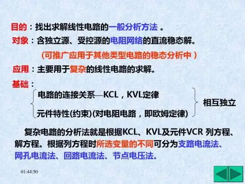
第四节 仿真电路
一、阻抗变换器
V ( s) Z1Z 3 Z 5 Zin I ( s) Z2Z4
当Z 2 1 , Z k Rk (k 1,2,3,4,5) sC2
R1 R3 R5 则Z in s C2 R4 等效电感Leq R1 R3 R5C2 R4
1 , 则Z in 2 c cC5 C1
频变电阻
D
1 2D
二.RLC-CRD变换: 如果用K/s乘以各个阻抗,其中K为任意常数,经变换后的电 路的电压转移函数仍将与原电路的相同。但电路中的各个元 件的性质发生了改变: 电容:
如
Vi ( s)
R
L
Vo ( s)
sL K s
若10log
1 1
2n
(100.1 A 1) A则n 2 log
取N=7
二、Chebyshev函数
1 H( j ) 1 2C2 n ( )
2
C0 ( ) 1 C1 ( ) Cn ( ) 2Cn 1 ( ) Cn 2 ( )
第三节 滤波函数的转换
经过频率域的变换,可实现滤波函数的变换。 一、低通函数→高通函数
H H( s ) 2 0 s s 1
p 1 s
H0s2 H( s ) 2 s s 1
物理意义: 电容: Z
1 sc
无源滤波器中元件变换
电感: Z sL
二、低通函数→带通函数
2 2 s 2 0 Q(sn 1) p sBW sn
作业:3-1,3-2
Design issues of analog filters: The analog filters using inductor works well at high frequencies, however, in low frequency applications that is in the frequency range (0- 20 kHz), the inductors cannot be used for the reasons : The size and weight of the inductors are large and physically bulky and the quality factor becomes very low Their characteristics are quite non-ideal Inductors are impossible to fabricate in monolithic form and are incompatible with any of the modern techniques for assembling electronic systems. Design analog filters without the use of inductors-simulated inductor.
