
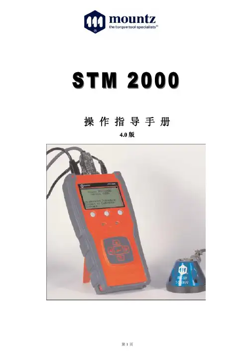
STM2000中文操作手册
- 格式:pdf
- 大小:2.60 MB
- 文档页数:31

报警中心管理软件使用说明书卓越2000 注意事项1.时间格式为HH:mm2.日期格式为dd-MM-yyyy3.屏幕区域更改为1024 x 768 象素,16位增强色4.安装目标目录须自行更改为c:\Mega 子目录5.虚拟盘已告取消6.MSDOS已告取消7.信号栏的数目由50个增多至200个8.报警音响更改为“电脑喇叭”和“声卡音箱”重复交替9.电子地图更改为800 x 600 象素10.住宅小区中的“隐蔽”楼层/平面图更改为“显示”11.计算机的运行速度须在 1.6G 以上,128M 内存12.使用微软Microsoft Windows 2000 (Professional) 简体中文版,并使用NTFS 文件系统格式化磁盘分区13.打印机自检功能暂时取消.14. 其它原有功能,保持不变.目录一、M S2000软件的功能,特点概述,注意事项――――――第3页二、M S2000软件电脑配置说明―――――――――――――第3页三、M S2000升级版本―――――――――――――――第3页四、如何安装软件――――――――――――――――――第3页五、M S2000软件操作简介―――――――――――――第4页(一)用户资料――――――――――――――――――第5页(二)讯号记录――――――――――――――――――第7页(三)系统设置――――――――――――――――――第8页(四)报警信息及处理―――――――――――――――第10页六、M S3000软件使用说明――――――――――――――第12页(一)如何绘制用户平面图―――――――――――――(二)如何绘用户平面图加入报警标识――――――――七、MS4000软件使用说明――――――――――――――八、MS8000软件合理说明书―――――――――――――(一)输入用户资料―――――――――――――――――(二)楼宇设定――――――――――――――――――(三)设置楼宇图标―――――――――――――――――(四)住户及其平面图报警图标设置―――――――――*请不要删除和修改用户资料库中的0000用户MS2000软件是FBI联网报警中心电脑中文管理软件,以中文WIN98,WIN2000为操作环境. 菜单式设计,易学易懂。
STM32F10xxx参考手册参考手册小,中和大容量的STM32F101xx, STM32F102xx和STM32F103xxARM内核32位高性能微控制器导言本参考手册针对应用开发,提供关于如何使用小容量、中容量和大容量的STM32F101xx、STM32F102xx或者STM32F103xx微控制器的存储器和外设的详细信息。
在本参考手册中STM32F101xx、STM32F102xx和STM32F103xx被统称为STM32F10xxx。
STM32F10xxx系列拥有不同的存储器容量,封装和外设配置。
关于订货编号、电气和物理性能参数,请参考STM32F101xx、STM32F102xx和STM32F103xx 的数据手册。
关于芯片内部闪存的编程,擦除和保护操作,请参考STM32F10xxx闪存编程手册。
关于ARM Cortex™-M3内核的具体信息,请参考Cortex™-M3技术参考手册。
相关文档● Cortex™-M3技术参考手册,可按下述链接下载:/help/topic/com.arm.doc.ddi0337e/DDI0337E_cortex_m3_r1p1_trm.pdf下述文档可在ST网站下载(/mcu/):● STM32F101xx、STM32F102xx和STM32F103xx的数据手册。
● STM32F10xxx闪存编程手册。
* 感谢南京万利提供原始翻译文档目录1文中的缩写 161.1寄存器描述表中使用的缩写列表 161.2术语表161.3可用的外设16 2存储器和总线构架 172.1系统构架172.2存储器组织182.3存储器映像192.3.1嵌入式SRAM 202.3.2位段202.3.3嵌入式闪存 212.4启动配置23 3CRC计算单元(CRC) 253.1CRC简介253.2CRC主要特性253.3CRC功能描述253.4CRC寄存器263.4.1数据寄存器(CRC_DR) 263.4.2独立数据寄存器(CRC_IDR) 263.4.3控制寄存器(CRC_CR) 273.4.4CRC寄存器映像 27 4电源控制(PWR) 284.1电源284.1.1独立的A/D转换器供电和参考电压 284.1.2电池备份区域 294.1.3电压调节器 294.2电源管理器294.2.1上电复位(POR)和掉电复位(PDR) 294.2.2可编程电压监测器(PVD) 304.3低功耗模式304.3.1降低系统时钟 314.3.2外部时钟的控制 314.3.3睡眠模式 314.3.4停止模式 324.3.5待机模式 334.3.6低功耗模式下的自动唤醒(AWU) 344.4电源控制寄存器 354.4.1电源控制寄存器(PWR_CR) 354.4.2电源控制/状态寄存器 364.4.3PWR寄存器地址映像 37 5备份寄存器(BKP) 385.1BKP简介385.2BKP特性385.3BKP功能描述385.3.1侵入检测 385.3.2RTC校准 395.4BKP寄存器描述 395.4.1备份数据寄存器x(BKP_DRx) (x = 1 … 10) 395.4.2RTC时钟校准寄存器(BKP_RTCCR) 395.4.3备份控制寄存器(BKP_CR) 405.4.4备份控制/状态寄存器(BKP_CSR) 405.4.5BKP寄存器映像 42 6复位和时钟控制(RCC) 456.1复位456.1.1系统复位 456.1.2电源复位 456.1.3备份域复位 466.2时钟466.2.1HSE时钟 486.2.2HSI时钟 486.2.3PLL 496.2.4LSE时钟 496.2.5LSI时钟496.2.6系统时钟(SYSCLK)选择 506.2.7时钟安全系统(CSS) 506.2.8RTC时钟 506.2.9看门狗时钟 506.2.10时钟输出 506.3RCC寄存器描述 516.3.1时钟控制寄存器(RCC_CR) 516.3.2时钟配置寄存器(RCC_CFGR) 526.3.3时钟中断寄存器 (RCC_CIR) 546.3.4APB2外设复位寄存器 (RCC_APB2RSTR) 566.3.5APB1外设复位寄存器 (RCC_APB1RSTR) 586.3.6AHB外设时钟使能寄存器 (RCC_AHBENR) 606.3.7APB2外设时钟使能寄存器(RCC_APB2ENR) 616.3.8APB1外设时钟使能寄存器(RCC_APB1ENR) 626.3.9备份域控制寄存器 (RCC_BDCR) 656.3.10控制/状态寄存器 (RCC_CSR) 666.3.11RCC寄存器地址映像 68 7通用和复用功能I/O(GPIO和AFIO) 697.1GPIO功能描述697.1.1通用I/O(GPIO) 707.1.2单独的位设置或位清除 717.1.3外部中断/唤醒线 717.1.4复用功能(AF) 717.1.5软件重新映射I/O复用功能 717.1.6GPIO锁定机制 717.1.7输入配置 717.1.8输出配置 727.1.9复用功能配置 737.1.10模拟输入配置 737.2GPIO寄存器描述 757.2.1端口配置低寄存器(GPIOx_CRL) (x=A..E) 757.2.2端口配置高寄存器(GPIOx_CRH) (x=A..E) 757.2.3端口输入数据寄存器(GPIOx_IDR) (x=A..E) 767.2.4端口输出数据寄存器(GPIOx_ODR) (x=A..E) 767.2.5端口位设置/清除寄存器(GPIOx_BSRR) (x=A..E) 777.2.6端口位清除寄存器(GPIOx_BRR) (x=A..E) 777.2.7端口配置锁定寄存器(GPIOx_LCKR) (x=A..E) 777.3复用功能I/O和调试配置(AFIO) 787.3.1把OSC32_IN/OSC32_OUT作为GPIO 端口PC14/PC15 787.3.2把OSC_IN/OSC_OUT引脚作为GPIO端口PD0/PD1 787.3.3CAN复用功能重映射 797.3.4JTAG/SWD复用功能重映射 797.3.5ADC复用功能重映射 807.3.6定时器复用功能重映射 807.3.7USART复用功能重映射 817.3.8I2C 1 复用功能重映射 827.3.9SPI 1复用功能重映射 827.4AFIO寄存器描述 837.4.1事件控制寄存器(AFIO_EVCR) 837.4.2复用重映射和调试I/O配置寄存器(AFIO_MAPR) 837.4.3外部中断配置寄存器1(AFIO_EXTICR1) 867.4.4外部中断配置寄存器2(AFIO_EXTICR2) 867.4.5外部中断配置寄存器3(AFIO_EXTICR3) 877.4.6外部中断配置寄存器4(AFIO_EXTICR4) 877.5GPIO 和AFIO寄存器地址映象 88 8中断和事件 898.1嵌套向量中断控制器 898.1.1系统嘀嗒(SysTick)校准值寄存器 898.1.2中断和异常向量 898.2外部中断/事件控制器(EXTI) 918.2.1主要特性 918.2.2框图928.2.3唤醒事件管理 928.2.4功能说明 928.2.5外部中断/事件线路映像 948.3EXTI 寄存器描述 958.3.1中断屏蔽寄存器(EXTI_IMR) 958.3.2事件屏蔽寄存器(EXTI_EMR) 958.3.3上升沿触发选择寄存器(EXTI_RTSR) 968.3.4下降沿触发选择寄存器(EXTI_FTSR) 968.3.5软件中断事件寄存器(EXTI_SWIER) 978.3.6挂起寄存器(EXTI_PR) 978.3.7外部中断/事件寄存器映像 98 9DMA 控制器(DMA) 999.1DMA简介999.2DMA主要特性999.3功能描述1009.3.1DMA处理 1009.3.2仲裁器1009.3.3DMA 通道 1019.3.4可编程的数据传输宽度,对齐方式和数据大小端 1029.3.5错误管理 1039.3.6中断1039.3.7DMA请求映像 1049.4DMA寄存器1079.4.1DMA中断状态寄存器(DMA_ISR) 1079.4.2DMA中断标志清除寄存器(DMA_IFCR) 1089.4.3DMA通道x配置寄存器(DMA_CCRx)(x = 1…7) 1089.4.4DMA通道x传输数量寄存器(DMA_CNDTRx)(x = 1…7) 1109.4.5DMA通道x外设地址寄存器(DMA_CPARx)(x = 1…7) 1109.4.6DMA通道x存储器地址寄存器(DMA_CPARx)(x = 1…7) 1109.4.7DMA寄存器映像 111 10模拟/数字转换(ADC) 11310.1ADC介绍11310.2ADC主要特征11310.3ADC功能描述11410.3.1ADC开关控制 11510.3.2ADC时钟 11510.3.3通道选择 11510.3.4单次转换模式 11510.3.5连续转换模式 11610.3.6时序图11610.3.7模拟看门狗 11610.3.8扫描模式 11710.3.9注入通道管理 11710.3.10间断模式 11810.4校准11910.5数据对齐11910.6可编程的通道采样时间 12010.7外部触发转换12010.8DMA请求12110.9双ADC模式12110.9.1同步注入模式 12210.9.2同步规则模式 12310.9.3快速交替模式 12310.9.4慢速交替模式 12410.9.5交替触发模式 12410.9.6独立模式 12510.9.7混合的规则/注入同步模式 12510.9.8混合的同步规则+交替触发模式 12510.9.9混合同步注入+交替模式 12610.10温度传感器12610.11ADC中断12710.12ADC寄存器描述 12810.12.1ADC状态寄存器(ADC_SR) 12810.12.2ADC控制寄存器1(ADC_CR1) 12910.12.3ADC控制寄存器2(ADC_CR2) 13110.12.4ADC采样时间寄存器1(ADC_SMPR1) 13310.12.5ADC采样时间寄存器2(ADC_SMPR2) 13310.12.6ADC注入通道数据偏移寄存器x (ADC_JOFRx)(x=1..4) 13410.12.7ADC看门狗高阀值寄存器(ADC_HTR) 13410.12.8ADC看门狗低阀值寄存器(ADC_LRT) 13410.12.9ADC规则序列寄存器1(ADC_SQR1) 13510.12.10ADC规则序列寄存器2(ADC_SQR2) 13510.12.11ADC规则序列寄存器3(ADC_SQR3) 13610.12.12ADC注入序列寄存器(ADC_JSQR) 13610.12.13ADC 注入数据寄存器x (ADC_JDRx) (x= 1..4) 13710.12.14ADC规则数据寄存器(ADC_DR) 13710.12.15ADC寄存器地址映像 138 11数字/模拟转换(DAC) 14011.1DAC简介14011.2DAC主要特征14011.3DAC功能描述14111.3.1使能DAC通道 14111.3.2使能DAC输出缓存 14111.3.3DAC数据格式 14211.3.4DAC转换 14211.3.5DAC输出电压 14311.3.6选择DAC触发 14311.3.7DMA请求 14411.3.8噪声生成 14411.3.9三角波生成 14511.4双DAC通道转换 14511.4.1无波形生成的独立触发 14511.4.2带相同LFSR生成的独立触发 14611.4.3带不同LFSR生成的独立触发 14611.4.4带相同三角波生成的独立触发 14611.4.5带不同三角波生成的独立触发 14611.4.6同时软件启动 14711.4.7不带波形生成的同时触发 14711.4.8带相同LFSR生成的同时触发 14711.4.9带不同LFSR生成的同时触发 14711.4.10带相同三角波生成的同时触发 14711.4.11带不同三角波生成的同时触发 14811.5DAC寄存器14911.5.1DAC控制寄存器(DAC_CR) 14911.5.2DAC软件触发寄存器(DAC_SWTRIGR) 15111.5.3DAC通道1的12位右对齐数据保持寄存器(DAC_DHR12R1) 15211.5.4DAC通道1的12位左对齐数据保持寄存器(DAC_DHR12L1) 15211.5.5DAC通道1的8位右对齐数据保持寄存器(DAC_DHR8R1) 15211.5.6DAC通道2的12位右对齐数据保持寄存器(DAC_DHR12R2) 15311.5.7DAC通道2的12位左对齐数据保持寄存器(DAC_DHR12L2) 15311.5.8DAC通道2的8位右对齐数据保持寄存器(DAC_DHR8R2) 15311.5.9双DAC的12位右对齐数据保持寄存器(DAC_DHR12RD) 15411.5.10双DAC的12位左对齐数据保持寄存器(DAC_DHR12LD) 15411.5.11双DAC的8位右对齐数据保持寄存器(DAC_DHR8RD) 15411.5.12DAC通道1数据输出寄存器(DAC_DOR1) 15511.5.13DAC通道2数据输出寄存器(DAC_DOR2) 15511.5.14DAC寄存器映像 156 12高级控制定时器(TIM1和TIM8) 15712.1TIM1和TIM8简介 15712.2TIM1和TIM8主要特性 15712.3TIM1和TIM8功能描述 15812.3.1时基单元 15812.3.2计数器模式 16012.3.3重复计数器 16712.3.4时钟选择 16812.3.5捕获/比较通道 17112.3.6输入捕获模式 17312.3.7PWM输入模式 17412.3.8强置输出模式 17412.3.9输出比较模式 17512.3.10PWM模式 17612.3.11互补输出和死区插入 17812.3.12使用刹车功能 17912.3.13在外部事件时清除OCxREF信号 18012.3.14产生六步PWM输出 18112.3.15单脉冲模式 18212.3.16编码器接口模式 18312.3.17定时器输入异或功能 18512.3.18与霍尔传感器的接口 18512.3.19TIMx定时器和外部触发的同步 18712.3.20定时器同步 19012.3.21调试模式 19012.4TIM1和TIM8寄存器描述 19112.4.1控制寄存器1(TIMx_CR1) 19112.4.2控制寄存器2(TIMx_CR2) 19212.4.3从模式控制寄存器(TIMx_SMCR) 19312.4.4DMA/中断使能寄存器(TIMx_DIER) 19512.4.5状态寄存器(TIMx_SR) 19612.4.6事件产生寄存器(TIMx_EGR) 19712.4.7捕获/比较模式寄存器1(TIMx_CCMR1) 19812.4.8捕获/比较模式寄存器2(TIMx_CCMR2) 20012.4.9捕获/比较使能寄存器(TIMx_CCER) 20212.4.10计数器(TIMx_CNT) 20312.4.11预分频器(TIMx_PSC) 20412.4.12自动重装载寄存器(TIMx_ARR) 20412.4.13重复计数寄存器(TIMx_RCR) 20412.4.14捕获/比较寄存器1(TIMx_CCR1) 20512.4.15捕获/比较寄存器2(TIMx_CCR2) 20512.4.16捕获/比较寄存器3(TIMx_CCR3) 20512.4.17捕获/比较寄存器(TIMx_CCR4) 20612.4.18刹车和死区寄存器(TIMx_BDTR) 20612.4.19DMA控制寄存器(TIMx_DCR) 20812.4.20连续模式的DMA地址(TIMx_DMAR) 20812.4.21TIM1和TIM8寄存器图 209 13通用定时器(TIMx) 21113.1TIMx简介21113.2TIMx主要功能21113.3TIMx功能描述21213.3.1时基单元 21213.3.2计数器模式 21313.3.3时钟选择 22113.3.4捕获/比较通道 22313.3.5输入捕获模式 22513.3.6PWM输入模式 22513.3.7强置输出模式 22613.3.8输出比较模式 22613.3.9PWM 模式 22713.3.10单脉冲模式 22913.3.11在外部事件时清除OCxREF信号 23113.3.12编码器接口模式 23113.3.13定时器输入异或功能 23313.3.14定时器和外部触发的同步 23313.3.15定时器同步 23513.3.16调试模式 23913.4TIMx寄存器描述 24013.4.1控制寄存器1(TIMx_CR1) 24013.4.2控制寄存器2(TIMx_CR2) 24113.4.3从模式控制寄存器(TIMx_SMCR) 24213.4.4DMA/中断使能寄存器(TIMx_DIER) 24313.4.5状态寄存器(TIMx_SR) 24413.4.6事件产生寄存器(TIMx_EGR) 24513.4.7捕获/比较模式寄存器1(TIMx_CCMR1) 24613.4.8捕获/比较模式寄存器2(TIMx_CCMR2) 24913.4.9捕获/比较使能寄存器(TIMx_CCER) 25113.4.10计数器(TIMx_CNT) 25213.4.11预分频器(TIMx_PSC) 25213.4.12自动重装载寄存器(TIMx_ARR) 25213.4.13捕获/比较寄存器1(TIMx_CCR1) 25213.4.14捕获/比较寄存器2(TIMx_CCR2) 25313.4.15捕获/比较寄存器3(TIMx_CCR3) 25313.4.16捕获/比较寄存器4(TIMx_CCR4) 25313.4.17DMA控制寄存器(TIMx_DCR) 25413.4.18连续模式的DMA地址(TIMx_DMAR) 25413.4.19TIMx寄存器图 255 14基本定时器(TIM6和TIM7) 25714.1TIM6和TIM7简介 25714.2TIM6和TIM7的主要特性 25714.3TIM6和TIM7的功能 25814.3.1时基单元 25814.3.2计数模式 25914.3.3时钟源26114.3.4调试模式 26214.4TIM6和TIM7寄存器 26214.4.1控制寄存器1(TIMx_CR1) 26214.4.2控制寄存器2(TIMx_CR2) 26314.4.3DMA/中断使能寄存器(TIMx_DIER) 26314.4.4状态寄存器(TIMx_SR) 26414.4.5事件产生寄存器(TIMx_EGR) 26414.4.6计数器(TIMx_CNT) 26414.4.7预分频器(TIMx_PSC) 26514.4.8自动重装载寄存器(TIMx_ARR) 26514.4.9TIM6和TIM7寄存器图 266 15实时时钟(RTC) 26715.1RTC简介26715.2主要特性26715.3功能描述26715.3.1概述26715.3.2复位过程 26815.3.3读RTC寄存器 26815.3.4配置RTC寄存器 26915.3.5RTC标志的设置 26915.4RTC寄存器描述 27015.4.1RTC控制寄存器高位(RTC_CRH) 27015.4.2RTC控制寄存器低位(RTC_CRL) 27015.4.3RTC预分频装载寄存器(RTC_PRLH/RTC_PRLL) 27115.4.4RTC预分频器余数寄存器(RTC_DIVH / RTC_DIVL) 27215.4.5RTC计数器寄存器 (RTC_CNTH / RTC_CNTL) 27215.4.6RTC闹钟寄存器(RTC_ALRH/RTC_ALRL) 27315.4.7RTC寄存器映像 275 16独立看门狗(IWDG) 27616.1简介27616.2IWDG主要性能27616.3IWDG功能描述27616.3.1硬件看门狗 27616.3.2寄存器访问保护 27616.3.3调试模式 27616.4IWDG寄存器描述 27716.4.1键寄存器(IWDG_KR) 27716.4.2预分频寄存器(IWDG_PR) 27816.4.3重装载寄存器(IWDG_RLR) 27816.4.4状态寄存器(IWDG_SR) 27916.4.5IWDG寄存器映像 279 17窗口看门狗(WWDG) 28017.1WWDG简介28017.2WWDG主要特性 28017.3WWDG功能描述 28017.4如何编写看门狗超时程序 28117.5调试模式28217.6寄存器描述28217.6.1控制寄存器(WWDG_CR) 28217.6.2配置寄存器(WWDG_CFR) 28317.6.3状态寄存器(WWDG_SR) 28317.6.4WWDG寄存器映像 284 18灵活的静态存储器控制器(FSMC) 28518.1FSMC功能描述28518.2框图28518.3AHB接口28618.3.1支持的存储器和操作 28618.4外部设备地址映像 28718.4.1NOR和PSRAM地址映像 28818.4.2NAND和PC卡地址映像 28818.5NOR闪存和PSRAM控制器 28918.5.1外部存储器接口信号 29018.5.2支持的存储器及其操作 29118.5.3时序规则 29118.5.4NOR闪存和PSRAM时序图 29118.5.5同步的成组读 30418.5.6NOR闪存和PSRAM控制器寄存器 30818.6NAND闪存和PC卡控制器 31318.6.1外部存储器接口信号 31318.6.2NAND闪存/PC卡支持的存储器及其操作 31418.6.3NAND闪存、ATA和PC卡时序图 31418.6.4NAND闪存操作 31518.6.5NAND闪存预等待功能 31618.6.6NAND闪存的纠错码ECC计算(NAND闪存) 31718.6.7NAND闪存和PC卡控制器寄存器 31718.7FSMC寄存器地址映象 324 19SDIO接口(SDIO) 32519.1SDIO主要功能32519.2SDIO总线拓扑32519.3SDIO功能描述32819.3.1SDIO适配器 32919.3.2SDIO AHB接口 33619.4卡功能描述33619.4.1卡识别模式 33619.4.2卡复位33619.4.3操作电压范围确认 33719.4.4卡识别过程 33719.4.5写数据块 33819.4.6读数据块 33819.4.7数据流操作,数据流写入和数据流读出(只适用于多媒体卡) 33819.4.8擦除:成组擦除和扇区擦除 33919.4.9宽总线选择和解除选择 34019.4.10保护管理 34019.4.11卡状态寄存器 34219.4.12SD状态寄存器 34419.4.13SD I/O模式 34719.4.14命令与响应 34819.5响应格式35019.5.1R1(普通响应命令) 35119.5.2R1b 35119.5.3R2(CID、CSD寄存器) 35119.5.4R3(OCR寄存器) 35119.5.5R4(快速I/O) 35219.5.6R4b 35219.5.7R5(中断请求) 35219.5.8R6(中断请求) 35319.6SDIO I/O卡特定的操作 35319.6.1使用SDIO_D2信号线的SDIO I/O读等待操作 35319.6.2使用停止SDIO_CK的SDIO读等待操作 35319.6.3SDIO暂停/恢复操作 35419.6.4SDIO中断 35419.7CE-ATA特定操作 35419.7.1命令完成指示关闭 35419.7.2命令完成指示使能 35419.7.3CE-ATA中断 35419.7.4中止CMD61 35419.8硬件流控制35419.9SDIO寄存器35519.9.1SDIO电源控制寄存器(SDIO_POWER) 35519.9.2SDIO时钟控制寄存器(SDIO_CLKCR) 35519.9.3SDIO参数寄存器(SDIO_ARG) 35619.9.4SDIO命令寄存器(SDIO_CMD) 35619.9.5SDIO命令响应寄存器(SDIO_RESPCMD) 35719.9.6SDIO响应1..4寄存器(SDIO_RESPx) 35719.9.7SDIO数据定时器寄存器(SDIO_DTIMER) 35819.9.8SDIO数据长度寄存器(SDIO_DLEN) 35819.9.9SDIO数据控制寄存器(SDIO_DCTRL) 35819.9.10SDIO数据计数器寄存器(SDIO_DCOUNT) 36019.9.11SDIO状态寄存器(SDIO_STA) 36019.9.12SDIO清除中断寄存器(SDIO_ICR) 36119.9.13SDIO中断屏蔽寄存器(SDIO_MASK) 36219.9.14SDIO FIFO计数器寄存器(SDIO_FIFOCNT) 36419.9.15SDIO数据FIFO寄存器(SDIO_FIFO) 36419.9.16SDIO寄存器映像 365 20USB全速设备接口(USB) 36620.1USB简介36620.2USB主要特征36620.3USB功能描述36720.3.1USB功能模块描述 36820.4编程中需要考虑的问题 36920.4.1通用USB设备编程 36920.4.2系统复位和上电复位 36920.4.3双缓冲端点 37220.4.4同步传输 37320.4.5挂起/恢复事件 37420.5USB寄存器描述 37520.5.1通用寄存器 37520.5.2端点寄存器 38020.5.3缓冲区描述表 38220.5.4USB寄存器映像 385 21控制器局域网(bxCAN) 38721.1bxCAN简介38721.2bxCAN主要特点 38721.2.1总体描述 38821.3bxCAN工作模式 38921.3.1初始化模式 39021.3.2正常模式 39021.3.3睡眠模式(低功耗) 39021.3.4测试模式 39021.3.5静默模式 39021.3.6环回模式 39121.3.7环回静默模式 39121.4bxCAN功能描述 39221.4.1发送处理 39221.4.2时间触发通信模式 39321.4.3接收管理 39321.4.4标识符过滤 39521.4.5报文存储 39821.4.6出错管理 39921.4.7位时间特性 40021.5bxCAN中断40221.6CAN 寄存器描述 40321.6.1寄存器访问保护 40321.6.2控制和状态寄存器 40321.6.3邮箱寄存器 41121.6.4CAN过滤器寄存器 41521.6.5bxCAN寄存器列表 419 22串行外设接口(SPI) 42222.1SPI简介42222.2SPI和I2S主要特征 42222.2.1SPI特征42222.2.2I2S功能42322.3SPI功能描述42422.3.1概述42422.3.2SPI从模式 42622.3.3SPI主模式 42722.3.4单工通信 42822.3.5状态标志 42822.3.6CRC计算 42922.3.7利用DMA的SPI通信 42922.3.8错误标志 43022.3.9关闭SPI 43022.3.10SPI中断43022.4I2S功能描述43122.4.1I2S功能描述 43122.4.2支持的音频协议 43222.4.3时钟发生器 43722.4.4I2S主模式 43822.4.5I2S从模式 43922.4.6状态标志位 44022.4.7错误标志位 44122.4.8I2S中断44122.4.9DMA功能 44122.5SPI和I2S寄存器描述 44222.5.1SPI控制寄存器1(SPI_CR1)(I2S模式下不使用) 44222.5.2SPI控制寄存器2(SPI_CR2) 44322.5.3SPI 状态寄存器(SPI_SR) 44422.5.4SPI 数据寄存器(SPI_DR) 44522.5.5SPI CRC多项式寄存器(SPI_CRCPR) 44622.5.6SPI Rx CRC寄存器(SPI_RXCRCR) 44622.5.7SPI Tx CRC寄存器(SPI_TXCRCR) 44622.5.8SPI_I2S配置寄存器(SPI_I2S_CFGR) 44722.5.9SPI_I2S预分频寄存器(SPI_I2SPR) 44822.5.10SPI 寄存器地址映象 449 23I2C接口45023.1I2C简介45023.2I2C主要特点45023.3I2C功能描述45123.3.1模式选择 45123.3.2I2C从模式 45223.3.3I2C主模式 45423.3.4错误条件 45623.3.5SDA/SCL线控制 45723.3.6SMBus 45723.3.7DMA请求 45923.3.8包错误校验(PEC) 46023.4I2C中断请求46123.5I2C调试模式46223.6I2C寄存器描述46223.6.1控制寄存器1(I2C_CR1) 46223.6.2控制寄存器2(I2C_CR2) 46423.6.3自身地址寄存器1(I2C_OAR1) 46523.6.4自身地址寄存器2(I2C_OAR2) 46523.6.5数据寄存器(I2C_DR) 46523.6.6状态寄存器1(I2C_SR1) 46623.6.7状态寄存器2 (I2C_SR2) 46823.6.8时钟控制寄存器(I2C_CCR) 46923.6.9TRISE寄存器(I2C_TRISE) 47023.6.10I2C寄存器地址映象 471 24通用同步异步收发器(USART) 47224.1USART介绍47224.2USART主要特性 47224.3USART功能概述 47324.3.1USART 特性描述 47424.3.2发送器47524.3.3接收器47724.3.4分数波特率的产生 48024.3.5多处理器通信 48124.3.6校验控制 48224.3.7LIN(局域互联网)模式 48324.3.8USART 同步模式 48524.3.9单线半双工通信 48724.3.10智能卡48724.3.11IrDA SIR ENDEC 功能块 48824.3.12利用DMA连续通信 49024.3.13硬件流控制 49124.4USART中断请求 49224.5USART模式配置 49324.6USART寄存器描述 49424.6.1状态寄存器(USART_SR) 49424.6.2数据寄存器(USART_DR) 49524.6.3波特比率寄存器(USART_BRR) 49624.6.4控制寄存器1(USART_CR1) 49624.6.5控制寄存器2(USART_CR2) 49824.6.6控制寄存器3(USART_CR3) 49924.6.7保护时间和预分频寄存器(USART_GTPR) 50124.6.8USART寄存器地址映象 502 25器件电子签名 50325.1存储器容量寄存器 50325.1.1闪存容量寄存器 50325.2产品唯一身份标识寄存器(96位) 503 26调试支持(DBG) 50526.1概况50526.2ARM参考文献50626.3SWJ调试端口(serial wire and JTAG) 50626.3.1JTAG-DP和SW-DP切换的机制 50726.4引脚分布和调试端口脚 50726.4.1SWJ调试端口脚 50726.4.2灵活的SWJ-DP脚分配 50726.4.3JTAG脚上的内部上拉和下拉 50826.4.4利用串行接口并释放不用的调试脚作为普通I/O口 50826.5STM32F10xxx JTAG TAP 连接 50926.6ID 代码和锁定机制 50926.6.1微控制器设备ID编码 50926.6.2边界扫描TAP 51026.6.3Cortex-M3 TAP 51026.6.4Cortex-M3 JEDEC-106 ID代码 51126.7JTAG调试端口51126.8SW调试端口51226.8.1SW协议介绍 51226.8.2SW协议序列 51226.8.3SW-DP状态机(Reset, idle states, ID code) 51326.8.4DP和AP读/写访问 51326.8.5SW-DP寄存器 51326.8.6SW-AP寄存器 514 26.9对于JTAG-DP或SWDP都有效的AHB-AP (AHB 访问端口) 514 26.10内核调试515 26.11调试器主机在系统复位下的连接能力 515 26.12FPB (Flash patch breakpoint) 515 26.13DWT(data watchpoint trigger) 516 26.14ITM (instrumentation trace macrocell) 51626.14.1概述51626.14.2时间戳包,同步和溢出包 516 26.15MCU调试模块(MCUDBG) 51726.15.1低功耗模式的调试支持 51726.15.2支持定时器、看门狗、bxCAN和I2C的调试 51826.15.3调试MCU配置寄存器 518 26.16TPIU (trace port interface unit) 52026.16.1导言52026.16.2跟踪引脚分配 52026.16.3TPUI格式器 52226.16.4TPUI帧异步包 52226.16.5同步帧包的发送 52226.16.6同步模式 52226.16.7异步模式 52326.16.8TRACECLKIN在STM32F10xxx内部的连接 52326.16.9TPIU寄存器 52326.16.10配置的例子 524 26.17DBG寄存器地址映象 5241 文中的缩写1.1 寄存器描述表中使用的缩写列表在对寄存器的描述中使用了下列缩写:read / write (rw) 软件能读写此位。

DatasheetFUJITSU Software BS2000 LMS V3.5Library Maintenance SystemLMS is the central library management system in BS2000.LMS is used to create and manage program libraries, as well as to manage and edit the elements contained in those libraries.Program libraries are PAM files which are processed using the PLAM library access method (PLAM: Program Library Access Method). For that reason they are also referred to as PLAM libraries. The PLAM access method is included in the BS2000 basic configuration.LMS makes an excellent software development support tool, providing the following standout functions:standardized program library system, element version management, the SDF statement language, protection mechanisms which can also be used for elements, and options for automating program development and library management.LMS is a sophisticated and mature BS2000 standard product which supports program development, maintenance and documentation.Program librariesA program library is a file with a substructure. It contains elements (“members”) and a table of contents listing the stored elements. Each library has an entry in the system catalog. The user can specify the name and other file attributes, such as retention period or sharability.Storing multiple elements in a library relieves the load on the system catalog, since only the library is entered there, and not each element. What’s more, it also saves storage space, since the elements are stored in the library in compressed form.ElementsAn element is a logically related set of data, e.g. input/output data, a procedure, a link module or a source program. Each element in the library can be addressed individually.An element in a program library is uniquely identified by its type, its name and a version identifier. Multiple versions relating to one element type and name can also be stored.In addition to standard types for typical contents, users can define their own types using names up to 8 characters long (user types) in order to structure their libraries more efficiently and automate processing of library elements with the aid of procedures in a much more finely grained manner.Version managementExperience teaches us that software elements need to be changed frequently. For this reason they must be easy to change and the different versions must be uniquely identified.Symbolic version identifiers support library management automation. Examples available include: *HIGHEST, for the highest version identifier, and *INCREMENT, to increment an existing version identifier in accordance with a selectable rule.LMS provides compact storage of differential sets (deltas): elements which have been created from a prior element due to changes generally differ only slightly from their predecessor. With LMS, only the differences compared with the predecessor then need to be physically stored. When such element versions are read, these deltas are merged in again at the relevant points, thus making the complete element available to the user once more.Integration into the programming environmentThe utility routines of the programming environment, such as EDT, compilers etc., can directly access program libraries.Link-and-load modules can be stored directly in program libraries by all the compilers and by the BINDER link editor. However, LMS can also copy link-and-load modules that originate from the old linker-loader system with the TSOSLNK linkage editor into the program library.The LMS subroutine interface provides users with convenient options for processing LMS libraries and their contents, from directly within a user program (Assembler, C, COBOL). In this case LMS is loaded dynamically.Multiple access to program librariesA library can be opened by one or more users for both read-only and write access.An element can be read concurrently by a number of users, but can only be accessed for writing by one user at a time. While an element is open for writing, no other access – including read-only – is possible to this element. Other elements of the library can be accessed. Statement formatLMS supports the SDF statement format familiar from the BS2000 command language. Statements in ISP format continue to be supported for compatibility reasons. New functions are only provided in SDF format, however.Basic functionsLMS provides the following basic functions:⏹Creating and managing libraries⏹Adding elements to a library, copying elements into anotherlibrary, and outputting elements from a library into a file⏹Managing, listing and editing elements⏹Comparing elements⏹Making LMS functions available from within EDT⏹Maintaining a Last Access Date for elements⏹Defining default settings in a start file.Protection functionsLMS supports the use of passwords and basic access control lists (BACLs) to provide a comprehensive, multi-tiered protection concept for libraries and elements.When the SECOS product is deployed, the GUARDS subsystem can be used to set up an extended, user-definable access control mechanism for libraries and elements.Protection rights are transferred to the elements on request when files are added, and vice versa when elements are output into files.All security-related actions relating to libraries and elements can be logged by linking PLAM to the SAT subsystem (part of the SECOS product).When elements are deleted, data that is no longer required can be selectively overwritten with the value X'00' (security erase). Borrowing procedureThe borrowing mechanism provides a means of controlling access to elements that are being modified e.g. by several developers working on a project.An element can only be written if the writer has previously been entered as the current holder for the source version.During writing, a history comprising the return timestamp, the holder’s user ID and optionally a user-specific comment is added to the new element status.The processing status of an element is output as an attribute in the table of contents and can also be used as a selection criterion. Make functionalityThe make functionality familiar from and successfully employed in other operating systems is also available under LMS. Using make enables projects to be implemented efficiently, since only absolutely essential steps are performed. The interface is tailored to match the BS2000 system.For a given target object, the make function describes the source objects on which this target depends, and the actions leading to the creation of the target.Starting from the selected target object, all targets are created from new if the source objects of a target have changed since the last time the target was generated.TopicsAs well as the selected target object, all associated source objects represent further sub-targets which are handled similarly.A BS2000 procedure is created and can be launched synchronously or asynchronously.To allow the description to be reused, the sequence of LMS-specific make statements should be stored in a separate element, called a make file.Output of library information to S variablesLMS supports the output of selected data to S variables. This enables easy and efficient creation of command procedures (S procedures), e.g. for automated library administration.If structured variables and lists are to be used here, then the chargeable product SDF-P is a software prerequisite. Reorganizing librariesLMS reorganizes a library so that the maximum amount of disk space not currently used by elements is released.This enables the amount of disk space required for a library to be reduced. In contrast to copying and subsequently deleting the old library, no additional disk space (to the full size of the library!) is required for reorganizing a library.Unlike with the COPY method, however, after REORG-LIBRARY there can still be an amount of free space which, at a maximum, may be as large as the largest element in the library.Technical DetailsRequirementsTechnical Requirements Hardware BS2000 Business ServerTechnical Requirements Software BS2000/OSD-BC V8.0 or higher or OSD/XC V8.5Demands on the user Knowledge of BS2000Installation and operationOperating mode Interactive and batch modeImplementation language Assembler, SPLUser interface Commands in English, message texts in German/EnglishInstallation By the customer according to the release noticeDocumentation and trainingDocumentation LMS User GuideLMS Subroutine Interface on the manual server.Training See course offerPurchasingConditions This software product can be leased by the customer in accordance with theconditions for the use of software products.Ordering and delivery This software product may be obtained from your local Fujitsu TechnologySolutions GmbH regional office.Products/fts/products/In addition to BS2000, Fujitsu offers a full portfolio of other computing products: ■ Storage systems: ETERNUS■ Server: PRIMERGY, PRIMEQUEST, Fujitsu SPARC M10, BS2000 Mainframe■ Client Computing Devices: LIFEBOOK, STYLISTIC, ESPRIMO, FUTRO, CELSIUS ■ Peripherals: Fujitsu Displays, Accessories ■ Software ■ Network Solutions/fts/solutions Infrastructure Solutions are customer offerings created by bringing Fujitsu’sproducts, services and technologies togetherwith those from partners.Industry Solutions are tailored to meet the needs of specific verticals.Business and Technology Solutions provide a variety of technologies developed to tackle specific business issues such as security and sustainability, across many verticals. Services/fts/services/ Application Services support the development, integration, testing,deployment and on-going management of both custom developed and packaged applications.Business Services respond to the challenge of planning, delivering and operating IT in a complex and changing IT environment. Managed Infrastructure Services enable customers to deliver the optimal IT environment to meet their needs.To learn more about BS2000, please contact your Fujitsu sales representative, Fujitsu business partner, or visit our website. /fts/bs2000/global/about/environment/ Fujitsu Green Policy Innovation is ourworldwide project for reducing burdens on the environment. Using our global know-how, we aim to resolve issues ofenvironmental energy efficiency through IT. Please find further information at:/global/about/environment/© 2014 Fujitsu Technology Solutions GmbH Fujitsu and the Fujitsu logo are trademarks or registered trademarks of Fujitsu Limited in Japan and other countries. BS2000 is a trademark or a registered trademark of Fujitsu Technology Solutions GmbH in Germany and other countries. Othercompany, product and service names may be trademarks or registered trademarks of their respective owners.Technical data subject to modification and delivery subject to availability. Any liability that the data and illustrations are complete, actual or correct is excluded. Designations may be trademarks and/or copyrights of the respective manufacturer, the use of which by third parties for their own purposes may infringe the rights of such owner.More informationContactFujitsu Technology Solutions GmbHMies-van-der-Rohe-Straße 8, 80807 München Website: /fts 12 March, 2015 EN。