测距仪LM50 说明书
- 格式:pdf
- 大小:4.71 MB
- 文档页数:17
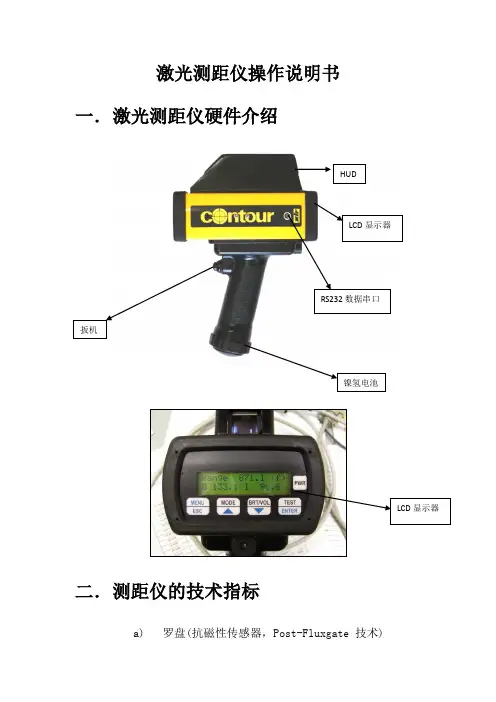
激光测距仪操作说明书一.激光测距仪硬件介绍HUDLCD显示器RS232数据串口扳机LCD显示器二.测距仪的技术指标a)罗盘(抗磁性传感器,Post-Fluxgate 技术)i."0.5 º 精确度b)磁倾仪i."0.1 º 倾斜精度ii."40 º 倾斜范围c)测距i.精度–测85米外的白目标精度为0.1米ii.最大距离–1850米(反射目标)iii.最小距离–3米iv.高压输电线175米v.杆状标志400米vi.树(无叶)400米vii.建筑物,树(有叶)800米三.激光测距仪的基本操作3.1 如何校对激光测距仪●开启电源●按“MENU” 健●用>?键来进行功能选择●选择“COMP” 并按下“Enter” 键●选择“CAL” 并按下“Enter” 键●LCD显示窗显示“Initializing Please Wait!” &“Rotate Unit for Calibration” 信息●以射击的姿势扣住扳机. LCD显示窗显示“Data PointCount” 信息●慢慢转动Contour枪1-2圈. 每圈用45-60秒钟完成●慢慢转动Contour枪1-2圈. 每圈用45-60秒钟完成●在转动中,慢慢地从上到下,从左到右移动(±40º的范围)●虽着 Contour 的移动, 你将看到数据点(Data PointCount) 在增加。
当其值增加到275时,罗盘校对操作就完成了。
松开板机,系统恢复原来的设置●每次系统上电都必须要重复以上操做3.2 开机自检自检信息:仪器开机后将进行自检,自检信息将显示在LCD 显示屏上:Selft TestControur XLRic当自检信息结束后回到以前的测量界面时,说明自检成功,否则会出现以下错误信息:End Of Self Test*** Fall3.3 标准测量模式下的测量标准模式是仪器在开机后默认的模式,在这种模式下,仪器将显示所测目标的距离、方位和倾斜值。
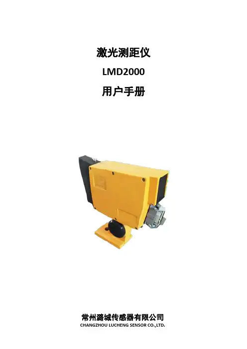
激光测距仪LMD2000用户手册常州潞城传感器有限公司目录1.0概述 (2)1.1系统原理 (2)1.2技术性能与指标 (2)1.3接线表 (3)2.0参数代码说明 (3)2.0.1模拟量输出范围的起点Range Beginning(RB) (3)2.0.2模拟量输出范围的终点Range End(RE) (3)2.0.3报警值选择(OPT) (4)2.0.4报警点1(DL) (4)2.0.5报警点2(DH) (4)2.0.6报警迟滞Alarm Hysteresis(AH) (5)2.0.7RS485或RS232选择 (6)2.0.8串口地址设置 (6)2.0.9软件版本号 (6)3.0操作说明 (7)3.0.1后面板示意图 (7)3.0.2参数设置过程 (7)3.0.2.1按键功能 (7)3.0.2.2参数设置步骤及说明 (7)4.0串口参数设定 (8)4.0.1串口连接 (8)4.0.2定义ASCII码RS485和RS232通讯协议 (8)4.0.2.1RS232通讯 (8)4.0.2.2RS485通讯 (10)5.0错误信息 (12)6.0机械尺寸 (12)1.0概述LMD2000激光测距仪专门用于对固定和移动物体的距离测量。
主要特点如下:•在恶劣的户外环境下,仍能保持很高的测量精度和可靠性•测量范围最大可达100米•使用可见激光束,易于瞄准被测物•灵活的可扩展的连接电缆,便于供电、电平信号、开关量和模拟量输出•可用不同的参数对开关量输出和模拟量输出分别编程•随意设定距离范围,并能用开关量输出表示距离的正负超差1.1系统原理LMD2000激光测距仪采用相位比较原理进行测量。
激光传感器发射不同频率的可见激光束,接收从被测物返回的散射激光,将接收到的激光信号与参考信号进行比较,最后,用微处理器计算出相应相位偏移所对应的物体间距离,可以达到mm级测量精度。
1.2技术性能与指标测量范围1:0.2~30m内,可直接测量;30~100米,需使用特制反射器测量精度2:0.2~30米:±2mm;30~100米:±3mm;分辨率:1mm激光发散角:0.6mrad供电电压:DC24V直流或交流AC(100~240)V(用户选择)数据接口:通过按键或串口(RS232或RS485)进行参数设置继电器输出:AC250V,10A;DC30V,5A响应时间小于320ms电平输出:PNP高电平DC24V,低电平0V;最大负载电流300mA;响应时间小于160ms。
徕卡测距仪使用说明书徕卡测距仪使用说明书:一、使用前的准备,一,电池的装入/更换打开仪器尾部的固定挡板。
向前推卡钮~向下将底座取下。
按住红色的卡钮推开电池盒盖。
安装或更换电池。
关闭电池盒盖~安装底座和卡扣。
当电池的电压过低时~显示屏上将持续闪烁显示电池的标志{B~21}。
此时应及时更换电池。
1、按照极性正确装入电池。
2、使用碱性电池,建议不要使用充电电池,。
3、当长时间不使用仪器时~请取出电池~以避免电池的腐蚀。
更换电池后~设置和储存的值都保持不变。
,二,多功能底底座固定挡板可以在下面的测量情况下使用:边缘测量~将固定挡板拉出~直到听到卡入的声音。
1、从2、从角落测量~将固定挡板拉出~直到听到卡入的声音~轻轻将固定挡板向右推~此时固定挡板完全展开。
仪器自带的传感器将辨认出固定挡板的位置~并将自动设置测量其准点。
,三,内置的望远镜瞄准器在仪器的右部有一个内置的望远镜瞄准器。
此望远镜瞄准器为远距离测量起到辅助的作用。
通过瞄准器上的十字丝可以精确地观察到测量目标。
在30米以上的测量距离~激光点会显示在十字线的正中。
而在30米以下的测量距离~激光点不在十字线中间。
,四,气泡一体化的水泡使仪器更容易调平。
,五,键盘1、开/测量键2、第二级菜单功能3、加+键4、计时,延迟测量,键5、等于[=]键6、面积/体积键7、储存键8、测量基准边键9、清除/关键10、菜单键11、照明键12、间接测量,勾股定律,键13、减-键14、BLUETOOTH ,六,显示屏1、关于错误测量的信息2、激光启动3、周长4、最大跟踪测量值5、最小跟踪测量值6、测量基准边7、调出储存值8、储存常数9、主显示10、单位~包括乘方立方,2/3,11、顶的面积12、墙面积13、3个额外显示,如:测量中间值,14、BLUETOOTH蓝牙开/关15、第二级菜单功能开16、硬件故障17、间接测量-利用勾股定律18、间接测量-利用勾股定律-部分高度19、面积/体积20、带常数的测量21、电池充电量显示二、菜单功能,一,设置在菜单中可以改变设置~并将其长久保存~并在关机和更换电池后不改变。
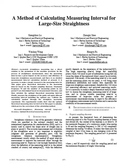
A Method of Calculating Measuring Interval forLarge-Size StraightnessShengzhou Luline 1:Mechanical and Electrical Engineering line 2: Harbin Institute of Technologyline 3: Harbin, Chinaline4:e-mail:*****************Zhongxi Shaoline 1:Mechanical and Electrical Engineering line 2: Harbin Institute of Technologyline 3: Harbin, Chinaline4:e-mail:*********************Weishun Wangline 1:Research and Development Center line 2: Qiqihar Heavy CNC Equipment CORP. LTDline 3: Qiqihar, Chinaline4:e-mail:138****************Hongya Fuline 1:Mechanical and Electrical Engineering line 2: Harbin Institute of Technologyline 3: Harbin, Chinaline4:e-mail:****************.cnAbstract—Accurately straightness measuring has a direct relation to the promotion of the machine precision. In the process of straightness measurement, since the measuring interval has a great impact on the accuracy and efficiency of large-size straightness measurement, and there is no detailed measurement interval calculation method at present, it is necessary to make a deeply research to the measuring interval. This paper gives theoretical derivation to the measuring interval based on the Nyquist sampling theorem. Maximum frequency M and the number of measuring points in one period N are determined based on measurement tolerance, and then calculate the optimal theoretical measuring interval. Finally, measure the straightess of the guide rail under diferent measuring interval including the optimal one. Validate the calculation method through the straightess measuring experiment. The experimental results show that the optimal theoretical measuring interval derived in this paper is suitable, which proves the correctness of the calculating method.Keywords-Straightness; Measuring interval; Large-size; Accuracy; Optimal theoretical measuring interval.I.I NTRODUCTIONStraightness tolerance is one of the geometric tolerances which are specified in the national standard and the international organization for standardization (ISO), and it is mainly used to control the shape error of straight line in plane or space[1]. The accurate measurement and evaluation of the straightness error is very important to eligibility judgment and guarantee of geometry parts with the straightness tolerance requirements[2]. Straightness measurement usually adopts the method of equal intervals measurement to measure the measured object through the measuring interval. There isn’t convincingly theoretical basis about the definition of the measuring interval in the related standard of country and enterprise[3], while the definition mostly depends on the experience of the technician[4][5]. The large measuring interval brings few measuring points,which will result in part of information losing that can cause the shape of the measured object cannot be accurately measured. Conversely, if the measuring interval is too small and the measuring points are too many, it will bring some interference information and useless data, especially for large-size straightness measurement, therefore this will cause low measuring efficiency and untrusted measuring results. So it is necessary to make a deeply theoretical analysis about how to choose the straightness measuring interval of large-size, and to choose suitable measuring interval in measurement of large-size under the premise of measurement requirement,aiming to improve the efficiency of straightness measurement and evaluation and to ensure the credibility of the measurement results.II.T HE DETERMINATION OF MEASURING INTERVAL IN LARGE-SIZE STRAIGHTNESS MEASUREMENTA.Nyquist sampling theoremAt present, the theoretical basis of determining the measuring interval is the Nyquist sampling theorem at home and abroad [6], the content of the theorem is as follows: If the maximum frequency of a continuous single value analog is M and the sampling frequency is 2M, it will completely determine the analog waveform. It means that there must be sampled at least twice times in one changing cycle of the maximum frequency. The sampling period now is presented by Eq.(1)12M∆<(1) where ∆and M respectively stand for sampling period and the maximum frequency of single value analog.International Conference on Chemical, Material and Food Engineering (CMFE-2015)The measuring interval corresponds to the sampling period of the signal in the time domain[7]. By the Nyquist sampling theorem, the number of measuring points in total length K can be determined by the maximum frequency M and the number of sampling in one changing cycle N of the maximum frequency. With the total measurement length L, the measuring interval can be determined as Eq.(2)=L L K MN∆= (2)where L,K,M and N respectively represent total measuring length, theoretical optimum measurement points in total measurement length, the maximum frequency and the number of sampling N in one changing cycle of the maximum frequency(2N >).It is observed that the measuring interval ∆ can be determined by total measurement length L, the maximum frequency M of the signal of the surface shape of the measured guide rail and the number of measuring points N in one changing cycle of the maximum frequency. Figure.1 describes the calculation process of theoretical measuringLarge-size StraightnessB. The determination of the maximum frequency MSince the determination of the maximum frequency of surface profile signal M is related with the measurement tolerance δ, there needs to introduce the measurement tolerance δ. The purpose of straightness measurement is to truly express the measured surface shape. The measurement errors from the measuring method and instrument will cause that the machining errors of the measured object cannot be accurately measured, so we should try to reduce measuring errors which mainly refers to errors from the method. Inpractice, the measurement method of equal interval is often used in straightness measurement, but the uncertainty of measuring interval brings the uncertainty of the position of measuring. The measuring errors from the method are mainly caused by mismatching between the measurement points and the extreme values points of the measured surface profile, and the measurement tolerance δ is used to restrict the measuring errors especially from measuring methods. Literature [8] points out that measurement tolerance δ relate with tolerance grade level and size of the measured object. By selecting the appropriate measurement tolerance δ based on the characteristics of the measured object, we can determine the maximum frequency M of the measured object surface shape of the signal.The error signal of the surface profile in the measured guide rail contains geometrical form error 、 surface waviness and surface roughness. In terms of frequency and amplitude, the low frequency and large amplitude makes the geometrical form error be the major factor affecting the surface appearance. The surface roughness frequency is high and amplitude is small. The frequency and amplitude of the surface wave are between both the above[9]. In the actual measurement, because of the difference of measured surface, the maximum frequency M of surface profile signal is not the same. The specific way to determine the M is to find out the former M order harmonic components of the measured surface profile signal, then compare each order harmonic amplitude with the measurement tolerance δ, find the maximum frequency M whose amplitude is above the measurement tolerance δ.In summary, according to the selected measuring interval determined by the total length L of the measured object and related national standards, measure the object and get the measurement data, and then modify the data through least square method to eliminate the influence of the installation inclination of the measured surface. Process the revised data by Fourier transform and data X(k) after Fourier transform which is described as Eq.(3)21()[()]()j ikn ni X k DFT x i x i eπ−−===∑ (3)where x(i) and n respectively represent the original measurement data and the total number of measuring points. Compare each order harmonic amplitude C i with the measurement tolerance δ, find the harmonic C m whose amplitude is above the measurement tolerance δ and order is the highest, then the maximum frequency is M.C. The determination of the number of meauring points in one cycle NIn the process of straightness measurement,the extreme values ultimately determine the straightness error value. Any one periodic signal can be formed by a number of sinusoidal signals, so we can assume that the measured surface profile is a sine wave, its period is T and its amplitude is a as Figure.2 describes, then we can see B and D is the determinant to straightness error value. As can be seen from Figure.2, thedecrease of the measuring interval will make the measurement points much closer to the extreme values points and then finally decrease the deviation caused by the mismatching between the measurement points and the extreme values points. But the decrease of the measuring interval and the increasing of the measurement points reduce the measurement efficiency and increase the amount of calculation, there is need to discuss the optimum number of Y PositionAssume that the number of measuring points in one changing cycle of the maximum frequency on the measured surface is N, the amplitude of the frequency component is a and its period T=2π,so the measuring interval is 2π/N . The measuring starting point is zero A, and B fall between K and K+1(K=0,1,2……N ), then the difference between K and B ∆Y K. and K and B ∆Y K+1 are determined as Eq.(4) and Eq.(5)sin(2/)Y a a K N K π∆=− (4)sin(2(+1)/)+1Y a a K N K π=−∆ (5) In actual measurement, the position of the measured point is unknown. Assume that the actual positions of the measured points and the measuring point position deviation is △X, then the difference of B value and K and K+1 point measurements are respectively determined as Eq.(6) and Eq.(7) sin((2/N)X)K Y a a K π∆=−+∆ (6) 1sin((2(1)/N)X)K Y a a K π+∆=−++∆ (7) Point B is between point K and point K+1, so when the actual position of measuring point changes, the variation trend of ΔY K and ΔY K+1 is just the opposite, one increases, another reduces. It can be proved that the limitation of measurement error caused by the mismatching between the measurement points and the extreme values points.ΔY K =ΔY K+1, the change of the actual measurement point △X is as Eq.(8) (42)/(2)X N K N π∆=−− (8) Take Eq.(8) into Eq.(6) and Eq.(7), the limit of measurement error near B is as Eq.(9) max (1cos(/N))B Y a π∆=− (9) Similarly, the limit of measurement error near the extreme value point D is as Eq.(10) max (1cos(/N))D Y a π∆=− (10)Therefore, the limit of straightness measurement error ΔY max caused by mismatching between the measurement points and the extreme values points are determined as Eq.(11)max max max2(1cos(/N))B D Y Y Y a π∆=∆+∆=−(11)As can be seen from Eq(11), with the number of measuring points N increasing,limit error of straightness measurement gets smaller. Therefore, as long as we know the amplitude of the maximum frequency of the measured surface signal a , we can get the number of measuring in one cycle of the maximum frequency N with measurement tolerance δ.D. Determination of straightness measuring interval Δ Combine the maximum frequency M and the number of sampling in one changing cycle of the maximum frequency N , we can get the number of measuring points K in the total measuring length which descibes the determination of theoretically optimal measuring points as Eq.(12) =K MN(12) And theoretically optimal measuring interval in total measurement length is determined as Eq.(13)=L L K MN∆= (13)III. E XPERIMENTAL VERIFICATION TO THE CALCULATIONMETHOD FOR MEASURING INTERVAL OF L ARGESTRAIGHTNESS Theoretically optimal measuring interval can be deduced according to the large-size straightness measuring interval calculation method with the original experimental data obtained. Validate the theoretically optimal measuring interval derived in this paper is reasonable, through measuring the straightness by different measuring interval including the optimal one.The measuring object in experiment is straightness within the vertical plane of the 5m guide rail whose accuracy index T is 0.02mm and the measuring instruments is Renishaw XL-80 laser interferometer. In order to eliminate the effect of the tilt of the rail to straightness measurements, use the least squares method to assess the straightness. It is recommended that the measurement tolerance δ in the calculation can be T/5~T/10.Figure.3 Measuring the Straightness of Guide Rail The length of bridgeboard used in straightness measurement are 160mm,500mm,750mm and 1000mm. Figure.3 describes straightness measurement by Renishaw XL-80 laser interferometer. TABLE 1 describes the impact of different measurement tolerance δto the measuring intervals that are derived.TABLE 1 The Impact of Different Measurement Tolerance δ to theMeasuring IntervalsMeasurement tolerance Theoretically optimal measuring interval [mm] δ=T/10 544δ=T/8 544δ=T/6 620δ=T/5 620As can be seen from TABLE 1, the theoretically optimal measuring interval derived under the case of δ=T/10 is 544mm, so the raw data obtained by the 160mm can be used to calculate as true values. TABLE 2 below describes the results of straightness measurement under the case of different measuring intervals by laser interferometer.TABLE 2 Straightness under Different Measuring IntervalsMeasuring interval [mm] Straightness [μm]160 40.922500 43.782750 33.81000 26.846The theoretically optimal measuring interval derived is about 550mm, and the interval less than 550mm can be used in practical. Taking the purpose of measuring efficiency and true expression of the straightness of the measured object into account, we can choose 500mm as measuring interval. As can be seen from TABLE 2, the results of straightness measurement got under the case of interval 160mm and 500mm are basically the same, while the results are significantly smaller under the case of interval 750mm and 1000mm, so the interval 500mm can be the optimal measuring interval.IV.C ONCLUSIONThis article proposes a calculation method for the large-size straightness measuring interval based on Nyquist sampling theorem. The results of validation experiments indicate that the method is feasible. According to the rail experimented, the interval 500mm through theoretical derivation can be its optimal measuring interval. Because the measurement tolerance δis from experiment in this paper, the subsequent research should give theoretical derivation and inspect the relationship between the measurement tolerance δ and measurement length.A CKNOWLEDGMENTThis work is supported by the National Science and Technology Major Project of China (2013ZX04013-011-09) and Heilongjiang Postdoctoral Fund in 2013 (LBH-Z13209). The authors would like to express their appreciation to the contribution of Xiaozhong Lou and Zhonghe Xu, who are the engineers at Qiqihar Heavy CNC Equipment CO., LTD, for offering help in experiments.R EFERENCES[1] F.G. Huang. The Number of Measurement Extraction Points forStraightness Error Evaluation[J]. Journal of Huaqiao university: Natural Science Edition, 2011, 32(6): 615-617.[2] F.G. Huang and Y.J. Zheng. Research straightness error measurementsampling scheme[J].Tool and Technology, 2007,10:95-98.[3]X.F. Hou. Research of Sampling Spacing in Measuring StraightnessBased on CMM[J].Tool and Technology, 2008, 42(6): 102-103. [4]M. M. Dowling, P. M. Griffin, K.-L. Tsui and C. Zhou. StatisticalIssues in Geometric Feature Inspection Using Coordinate Measuring Machines. Tchnometrics, 1997,39(1)3~24.[5] A. Weckenmann, H. Eitzert, M. Garmer and H. Weber. Functionality-Oriented Evaluation and Sampling Strategy in Coordinate Metrology.Precision Engineering,1995,17:244~252.[6]Y.H Zheng, L.N. Zhang and K.W. Qing. Extraction scheme of the newgeneration GPS and its application research[J]. Machinery Design & Manufacture, 2008 (6): 193-194.[7]L.L. Huang, L.X. Wang, Yu Wang, H.L. Wang and F.G. Huang.Extraction of Straightness Error Signal with Harmonic Analysis. [J].Journal of Huaqiao university: Natural Science Edition, ,2014,01:7-10.[8]Z Li and Z.G. Xu and X.Q.Jiang. Interchangeability andMeasurement Technology——Geometrical Product Specifications and Verification(Higher Education Press,China 2004). pp.67.[9] B.Fei, Y.J. Fan and WenXiong Xu. Adaptive Sampling Method——Anew method used in measuring the shape error[J]. Journal of Applied Sciences, 1994, 12(4): 423-430.[10]F.X Zhang and H. Zhao. Theoretical research between sample step anddeviation shape in straightness measurement[J]. Aiavtion method & measurement technology. 1995, 15(2): 9-11.。
lomvum测距仪说明书Lomvum测距仪是一款精密测量工具,可以快速、准确地测量各种长度、面积、体积以及间距等。
一、产品外观Lomvum测距仪外观简洁,主要由测量部分、显示屏、控制按键和电池仓组成。
二、产品特点1、高精度测量:Lomvum测距仪采用激光技术,具有高精度、高速度的测量能力,测量范围从0.05米到60米不等。
2、多功能:Lomvum测距仪支持长度、面积、体积、连续测量、最大/最小值测量等多种测量方式,满足不同测量需求。
3、易操作:Lomvum测距仪采用大尺寸LCD液晶显示屏,界面简洁、易读,同时操作简单方便,适用于各种人群使用。
4、自动校准:Lomvum测距仪自动支持校准,准确度高,保证了测量数据的可靠性。
三、使用方法1、按下电源键开启测距仪,在显示屏上可以看到“0.00”数值。
2、选择需要进行的测量方式:(1) 按功能键进行选择,如:长度、面积、体积等。
(2) 点击单位键,选择需要的单位,如:米/英尺/英寸等。
3、使用参考位标记测量:(1) 将测量仪对准需要测量的起始点,按下“测量”按键。
(2) 将测量仪对准需要测量的终点,按下“测量”按键。
(3) 显示屏会显示所测得的数值。
4、键入参数测量:(1) 直接通过键盘键入需要测量的数值,然后按下“测量”按键。
(2) 显示屏会显示所测得的数值。
5、最大/最小测量:(1) 点击“MAX/MIN”键,选择需要测量的模式。
(2) 将测量仪对准需要测量的目标,按下“测量”按键。
(3) 显示屏会显示所测得的最大/最小数值。
四、注意事项1、使用时请避免阳光直射、划痕、碰撞等情况。
2、请使用干燥的抹布清洁测距仪,避免使用含酸性或碱性的清洁剂。
3、使用时请遵循使用说明,避免误操作或酿成其他危害。
4、在不使用时请关闭电源,避免耗电等情况。
5、Lomvum测距仪只能在室内环境下使用,不能在室外使用,避免影响精度。
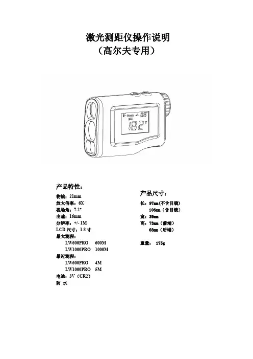
激光测距仪操作说明(高尔夫专用)产品特性:物镜:21mm放大倍率:6X视场角:7.2°出瞳:16mm分辨率:+/-1MLCD尺寸:1.8寸最大测程:LW600PRO600MLW1000PRO1000M 最近测程:LW600PRO4MLW1000PRO5M电池:3V(CR2)防水产品尺寸:长:97mm(不含目镜)106mm(含目镜)宽:39mm高:73mm(前端)68mm(后端)重量:175g1、开机按键开机开机画面,是上次操作后的功能界面。
2、单位转换长按键可切换距离单位,M和Y。
在“测距”,“旗杆锁定”,“高尔夫距离修正”,“雾天”4种模式中,都可以通过长按键来切换M,Y单位,单位切换后将在4种模式中统一使用。
3、模式选择短按键可在“测距”,“旗杆锁定”,“高尔夫距离修正”,“雾天”,之间切换选择。
侧屏的内容将与望远镜内显示内容同步。
侧屏中有出现MD符号时表示显示的是实测距离,出现RD时表示显示的是建议距离。
3-1测距原理望远镜显示界面侧屏显示界面短按键开始测距望远镜显示界面侧屏显示界面3-2“旗杆锁定”模式原理说明在旗杆锁定模式中,可以将点D从众多的背景点中分离出来,并只保留该点的距离d1。
从而达到自动锁定旗杆,并清除旗杆背后的树林等杂散目标的目的。
望远镜显示界面侧屏显示界面在旗杆扫描模式画面出现后,按住启动旗杆扫描功能,此时画面中的旗帜周围的方框会闪动,将测距机的瞄准点在被测旗杆的两侧来回扫描,当旗杆的数据被测到后,数据将被保留,而画面中旗帜周围的方框也不再闪动,表示旗杆数据被锁定。
望远镜显示界面侧屏显示界面3-3高尔夫距离修正:将测距值AB与坡度值(<±20°)带入到高尔夫飞行弹道的方程中,根据距离解算出高尔夫的建议击球距离。
在坡度为正时,击球距离要远。
距离:AB点间距=AD点间距若按实际距离,击球抛物线为1,此时由于坡度为正,实际只能飞行到C 点。
要达到B点,需要按抛物线2击球,此时的飞行距离应该是AE点间的距离。

激光测距仪带速度测量功能的SNDWAYSW-600A,SW-1000A,SW-1500A具有距离、速度、坡度和高度测量功能的多功能设备操作说明该产品的设计符合标准:GB/T14267-2009广东制造,货号:00000950安全说明使用前仔细阅读安全要求和操作说明在使用该设备之前,请阅读所有的安全和操作说明。
任何未在这些说明中描述的措施都可能导致设备发生故障,影响测量的准确性或对用户或第三方造成伤害。
请勿自行打开或修理该装置。
严禁对激光发射器的功能做任何修改或调整。
妥善存放设备,不要让儿童接触到它,避免未经授权的人使用。
切勿将激光发射器对准自己或旁人,对准你身体的任何部位或任何高度反射的物体。
该设备的电磁辐射会对其他电子设备造成干扰。
不要在飞机上或医疗设备附近使用本装置。
不要在爆炸性或易燃性环境中使用本设备。
不要将废旧电池和无法使用的电器与家庭垃圾一起处理。
请按照现行法律和关于处理此类设备的规定来处理设备。
如果您在使用过程中遇到任何问题或疑问,请立即联系您的SNDWAY官方代表,我们将尽快帮助您解决问题。
感谢你购买SNDWAY手持式激光测距仪!带倾斜测量功能的SNDWAY多功能激光测距仪是一款集双筒望远镜和激光测距仪功能于一体的便携式激光倾斜测距仪。
主要应用。
•对于物体的详细检查,测量静态物体或低速移动且在可视范围内的物体。
该仪器的特点是测量精度高,测量速度快,可检测参数的可视化。
经济性:提供自动断电和低耗电。
•多功能激光测距仪结合了最新技术,可同时显示物体的距离和倾角。
在确定与物体的距离时,它可以显示到目标点的线路与地面的角度(仰角定义为正,俯角定义为负),相对高度和可见地平线的范围。
激光发射器的功率足够低,对人眼来说很安全。
它能够测量任何物体的范围,其体积小、重量轻,便于携带。
它由一个可充电的锂离子电池供电。
测距仪广泛用于电力设施(复杂的测量和扫描功能可以方便地检查远处的物体,如电力线和电线杆)、高速铁路、公用事业、林业设计、建筑、互联网通信设计、通信线路的检查和维修等,在开放的乡村和高尔夫、狩猎和野营旅行中使用。
测距仪说明书测距仪是一种仪器,主要用于测量物体之间的距离。
它可以用于各种应用,包括建筑、制造、测绘、激光标记和机器人等。
这是一种非常有用的工具,下面我们将为您介绍一下如何使用测距仪。
1. 开机使用测距仪前,需要将其开机。
按下电源按键,屏幕将显示菜单,然后进入测量模式。
2. 选择模式在菜单中选择适当的模式,例如测量距离、面积或体积。
选择模式后,设备将开始测量。
3. 对准目标在进行测量之前,需要先对准目标。
选择需要测量的对象,将测距仪对准目标并保持稳定。
4. 测量距离在目标对准之后,对其进行测量。
点击测量键,设备将发出一个激光束,直接照射到目标的表面。
设备将在屏幕上显示测量的数值。
如果需要进行连续测量,则可以按住测量键并更新结果。
5. 测量面积选中面积模式后,将激光射向首个角落,并使用设备的功能测量每个角落的距离。
在完全测量后,设备将计算面积并在屏幕上显示结果。
6. 测量体积如果需要测量物体的体积,则可以选择体积模式。
在测量距离和面积后,可以通过选择物体高度和单击计算键来完成测量。
7. 单次测量和连续测量测距仪可以执行一次或连续测量。
在单次测量中,设备进行一次测量并显示测量结果。
在连续测量中,设备将在点击测量键时连续进行测量,并显示测量结果。
8. 显示单位在使用设备时,需要选择合适的度量单位。
可以选择米、英尺、英寸等单位。
您将需要根据项目的需求选择适当的单位。
9. 存储测量结果测距仪还可以存储测量结果。
在测量完成后,可以将数据存储在设备的内存中,以备将来使用。
10. 翻转显示屏有些测距仪具有翻转显示屏的功能,可以根据使用者的需求实现自动翻转屏幕。
在使用过程中,还需要注意以下几点:1. 将设备保持平稳,以确保测量结果的正确性。
2. 在使用设备时要避免划痕或损坏。
3. 在不使用设备时,建议将其放置在盒子或软垫中以保护它。
4. 某些设备具有防水或防尘功能,但并不是所有设备都配备此类功能,使用前请确保知道设备的全面性。
测距传感器操作说明
一、接口
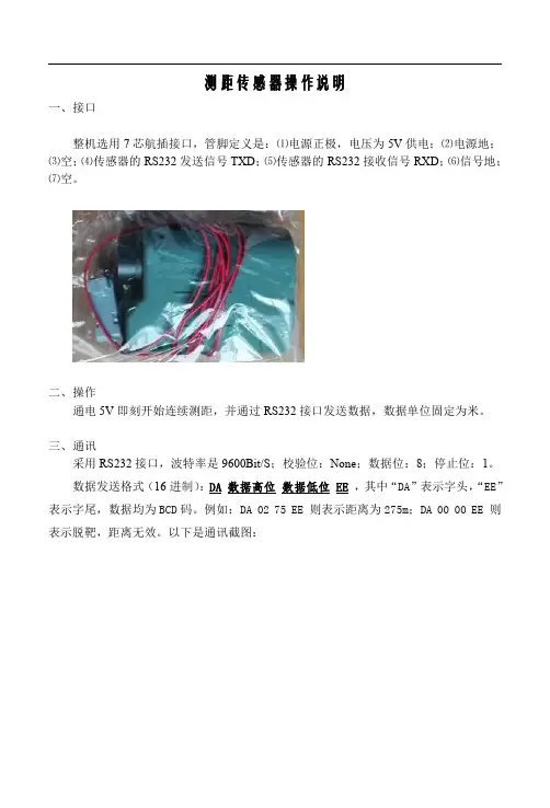
整机选用7芯航插接口,管脚定义是:⑴电源正极,电压为5V供电;⑵电源地;
⑶空;⑷传感器的RS232发送信号TXD;⑸传感器的RS232接收信号RXD;⑹信号地;
⑺空。
二、操作
通电5V即刻开始连续测距,并通过RS232接口发送数据,数据单位固定为米。
三、通讯
采用RS232接口,波特率是9600Bit/S;校验位:None;数据位:8;停止位:1。
数据发送格式(16进制):DA数据高位数据低位EE,其中“DA”表示字头,“EE”表示字尾,数据均为BCD码。
例如:DA0275EE则表示距离为275m;DA0000EE则表示脱靶,距离无效。
以下是通讯截图:
四、参数
1、供电:直流5V;
2、功耗:<1W;
3、最近测程:>5m;
4、最远测程:1500m;
5、最快频率:约30Hz(30m以内的近距离目标);
6、最慢频率:约0.8Hz(对空测量);
7、一般频率:约10Hz
8、重量:0.125kg
9、尺寸104*72*41mm
10、精度:正负1米。
测距仪使用说明Forestry pro measurement procedure guideTo start :开始1,press POWER button to turn on按电源键POWER打开2,confirm your mode with the internal display (default is “last used” setting)确认你的模式与内部显示(默认是“最后的使用“设置)3,Set your desired mode and start measuring设置你想要的模式,开始测量Mode setting:模式设置Target priority modes目标优先模式1、press and hold MODE button,then press and hold POWER button within 0.5 second.按下并保持住模式按钮,然后同时按住电源按钮在0.5秒之内2、Continue to press and hold both buttons(more than 2 seconds)until first target priority mode and distant target priority mode are switched.继续同时按住两个按钮(超过2秒),直到第一个目标优先模式和遥远的目标优先模式切换。
3、if the button is not pressed within 0.5 second ,the display unitwill be switched.如果按钮不是压在0.5秒之内,显示单元<米/码/英尺。
>将切换。
Dst:Distant priority mode (factory setting)遥远的优先模式(工厂设置)1st:first priority mode第一优先模式Measurement modes测量模式Press and release MODE button.按下和释放模式按钮Measurement mode changes in the order of 1 (Act)to 6 (Hor)as shown below.测量模式变化的顺序1(Act)到6(Hor)如下所示。
INSTRUCTION MANUALRemote Meter: MT50Thank you very much for selecting our product!This manual offers important information and suggestions with respect to installation, use and troubleshooting, etc. Please read this manual carefully before using the product.Remote MeterMT501 Important Safety Instructions (1)2 General Information (2)2.1 Features (2)2.2Main functions (3)2.3Recommendations (3)3 Installation (4)4 Product Features (8)5 Operation (12)5.1 Buttons (12)5.2 Main menu (13)5.3Real-time monitoring (14)5.4 Device information (16)5.5Test operation (16)5.6Control parameter (17)5.7Load setting (21)5.8Device parameter (24)5.9Device password (25)5.10Factory reset (25)5.11Failure information (26)5.12Meter parameter (27)6 T echnical Specifications (28)1 Important Safety InstructionsSAVE THESE INSTRUCTIONS:This manual contains important safety, installation and operating instructions for the Remote Meter.General safety information■Please inspect the MT50 thoroughly after it is delivered. If any damage is seen, please notify the shipping company or our company immediately. A photo of the damage may be helpful.■Read all instructions and cautions in the manual before starting the installation.■Keep the MT50 away from rain, exposure, severe dust, vibrations, corrosive gas and intense electromagnetic interference.■Do not allow water to enter remote meter.■There are no user serviceable parts inside the controller. Do not disassemble or attempt to repair it.2 General Information2.1 FeaturesThe new-generation remote display unit MT50 for the controllers is an associated display device which supports both the latest communication protocol and the voltage technology standard of solar controllers. The products have many excellent functions:■Automatic identify and display the type, model and relevant parameter data of controllers;■Real-time display the operational data and working status of the connection devices in digital, graphic and textual forms by a large-screen multifunction LCD;■Direct, convenient and rapid operation of six navigation function keys;■Both data and power flowing on the same lead, no need for external power;■Real-time data monitoring and remote load switchover of the controllers, and data browse and modification of device parameters, charge control parameters and load control parameters;■Real-time display of failure information of the connection devices;■Longer communication distance based on RS485.2.2 Main functionsFunctions like the real-time monitoring of the operational data and working status of a controller, the browse and modification of charge/discharge control parameters, the setting of device parameters and load control parameters and the restoration of factory defaults, based on LCD display and functional key operation.2.3 Recommendations■Please do not install MT50 in a situation with strong electromagnetic interference.3 InstallationFrame Mount Dimensions(mm)Wall installation steps:Step1: Locate and drill screw holesbased on the Frame Mounting dimensionof the base, and erect the plasticexpansion bolts;Step 2: Use four ST4.2×32 self-tappingscrews to fix the Frame;Frame MountingStep 3: Use four M4×8 pan head screws to mount MT50 Surface on the Frame;Step 4: Mount the four associated screw plugs into the screw holes.Surface MountingSteps of surface mounting:Step 1: Locate and drill screw holes based on the installation size of the Surface;Step 2: Use four M4×8 cross recessed pan head screws with M4 nuts to mount MT50 Surface onto the panel;Step 3: Mount the four associated white screw plugs into the screw holes.Surface mountingNote: Take full consideration of the plugging/unplugging space of the communication cable and the length of the cable during installation to see if they are appropriate.4 Product FeaturesRS485 communication and power interfaceRear ViewFailure indicatorFailure indicator flashes in case of failure of the connection devices. For failure information please check the Controller Manual.Communication indicatorIndicate communication status when MT50 is connected with the controller. Display screenMan-machine interaction operation interface.ButtonsThe Meter buttons includes four navigation buttons and two operational buttons. See the specific directions in the Operational Manual.RJ45 communication and power interfacesCommunication and power supply cable interfaces, used for communication connection with controllers.Note: Please use the communication plug which is marked with “MT”to connect MT50Monitoring screenDay and night icons-Night,- Day: The threshold voltage is 1V. Higher than 1V is daytime. Charge current iconThe icon is dynamically if there is charge current.Battery iconThe battery capacity is dynamically displayedNote: When the battery is in over discharge status, the icon displayed is“ ”.Battery status icons-Normal voltage, -Under voltage, -Over discharge.Load current iconThe icon is dynamically if there is discharge current.Load status icon- Load On, - Load Off.Note: In Manual Mode, pressing the "OK" button will switch the load status between "ON" and "OFF"5 Operation5.1 ButtonsThe buttons are respectively (from left to right) “ESC”,“Left”,“Up”,“Down”,“Right”and “O K “buttons, the operation is described in the schematic operation diagram below:Schematic operation diagramThe default entry page is the browse mode. Pressing button and inputting the correct password to enter the modification mode; and buttons could be used to move the cursor, and buttons could be used to modify the parameter values when the cursor is located at the current place;and buttons could be finally used to respectively confirm and cancel the modification of the control parameters.5.2 Main menuEnter the Main Menu by pressing "Esc".“Up”and “Down”buttons are respectively used to move the cursor to select the menu items, “OK”and “ESC”buttons are respectively used to enter or exit the corresponding pages of the menu items.5.3 Real-time monitoringThere are 14 pages under real-time monitoring. Please check it as below:17.5V 13.8V 13.8VOperational tips:Move between rows by pressing "Up" or "Down" buttons. Move along a row by pressing "Right" or "Left" buttons .5.4 Device informationThe product model, parameters and SN code of the controllers are displayed below:Operational tips: and buttons are respectively used to turn the browse page upward and downward.5.5 Test operationLoad switch test operation is conducted on the connection solar controller to see if the load output is normal. The test operation does not affect the working settings under actual load, which means that the solar controller will exit from the test mode when exiting the operational interface of the test.Operational tips: Enter the page and input correct password; use andbuttons to modify the On/Off status values, while use andbuttonsrespectively to confirm and cancel the test operation.5.6 Control parameterBrowse and modification operations are conducted over the control parameters of solar charge controller. See the scope of parameter modification in control parameters table, and the page of control parametersBattery voltage parameters(Parameters is in 12V system at 25℃ , please use X 2 in 24V, X 3 in 36 V, and X 4 in 48 V system)Notes:1. When the battery type is sealed, gel, flooded, the adjusting range of equalize duration is 0 to180min and boost duration is 10 to180min.2. The following rules must be observed when modify the parameters value in user battery type (factory default value is the same as sealed type):a) Over Voltage Disconnect Voltage > Charging Limit Voltage ≥ Equalize Charging Voltage ≥ Boost Charging Voltage ≥ Float Charging Voltage > Boost Voltage Reconnect.b) Over Voltage Disconnect Voltage > Over Voltage Reconnect Voltagec) Low Voltage Reconnect Voltage > Low Voltage Disconnect Voltage ≥ Discharging Limit Voltage.d) Under Voltage Warning Recover Voltage > Under Voltage Warning Voltage ≥ Discharging Limit Voltage.e) Boost Voltage Reconnect > Low Voltage Reconnect Voltage.NOTE: Please refer to user guide or contact with the sales for thedetail of setting operation.5.7 Load settingThe page of load setting could be used to set the four load working modes of the connection solar controller (Manual, Light on/off, Light on+timer, Time control)④Time control5.8 Device parameterThe software version information of solar charge controller could be checked via the page of device parameters, and device data like device ID, device LCD backlight time and device clock could be checked and modified. The page of device parameter in the diagram below:Note: the bigger the ID value of the connection device, the longer the Meter5.9 Device passwordThe password of the solar charge controller could be modified via the page of device password; the device password is a 6-digit figure which is required before entering the modification mode of “Control parameter”,“Load setting”, “Device parameter”,“Device password”,“Factory reset” pages. The page of device password in the diagram below:Note: Solar charge controller default password is”000000”5.10 Factory resetThe default parameter values of solar charge controller could be restored via the Factory reset page, which means the “Control parameter”,“Load setting”, “Charge mode” and “Device password” of the devices could be restored to the factory defaults (the factory default password of the devices is “000000”).5.11 Failure informationThe current failure information of the solar charge controller could be checked via the Failure information page (a maximum of 15 failure messages could be displayed); when the failures of solar charge controller are eliminated, the corresponding failure information will also be automatically eliminated.5.12 Meter parameterThe meter model, software and hardware version, and SN NO. could be checked via Meter parameter page. And the three parameters (Switch pages, Backlight) could be browsed and modified as well.Note: When the set up is accomplished, the auto switch page cannot6 Technical Specifications Electrical ParameterEnvironmental ParameterDefinitions of interface pinsData cable pin definitionsREMOTE METER DIMENSIONS (mm)Any changes without prior notice! Version number:V2.3。
高精度激光测距仪操作手册艾默生管道工具(上海)有限公司LM-100简易说明键位说明参数测量范围……………………………….0.05-50m测量精度(10m以内)…………….........±1.5mm测量单位………………………………m,in,ft激光等级………………………………二级激光类型………………………………635nm,<1mW防护等级………………………………IP54信息储存………………………………20条测量信息操作温度………………………………0°C - 40°C操作开关机:按开机/测量键开启仪表及激光。
长按清除数据/关机键关机。
调节测量基准点切换:开机后,机器默认的测量基准点切换是测距仪的尾部。
按参考点调节键,可以将参考点更改为测距仪的头部。
更改测量单位:长按背光/单位键。
清除显示数据及上次操作:按清除数据/关机键。
查看前20次测量结果:按历史数据键。
清除内存中的所有数据:同时按住历史数据键及清除键。
背光显示:按背光键开启或关闭背光显示。
单次测量:按开机/测量键开启测距仪,再次按开机/测量键进行一次测量。
连续测量,最大最小值记录:按连续测量键进入连续测量模式。
在此模式下,屏幕上第三行的测量值每0.5秒进行一次即时更新,相应的最大值及最小值动态的显示在第一行及第二行。
加减计算:按加/减将相邻的两个数据相加/减。
按清除数据/关机键取消上一次操作,再按清除数据/关机键回到单个数据。
面积计算:按面积/体积测量键,屏幕上将出现图标。
按开机/测量键测量第一段距离(例如长度),该值将显示在屏幕第一行。
然后再次按开机/测量键测量第二段距离(例如宽),该值将显示在屏幕第二行。
计算结果将出现在屏幕的第三行。
体积计算:连续按面积/体积测量键,屏幕上将出现图标。
然后进行与测量面积相同的操作,此时面积值将显示在屏幕的第三行,长及宽将分别显示在一,二行。
此时按开机/测量键,测量高度值,此值将显示在第二行。
VertexⅣ超声波测高测距仪使用说明1. 电源:VertexⅣ和T3都需要使用一节5号电池。
长期不用时请注意把电池取下来,以免电池损坏腐蚀电路。
2.按ON键开机,同时按DME键和IR键(两个箭头键)关机。
仪器不操作25秒后自动关机。
在测量前要等待仪器的温度与环境温度平衡,超过10分钟。
平衡后进行设定与标定。
标定好后可以测量。
“HD”直线距离,“DEG”角度,“H”高度3.SETUP(参数设置)所有的设置都在setup菜单里面可以设置。
按动ON键启动仪器,按动箭头键移到setup栏,再次按动ON键进入setup设置窗口。
以下四个参数逐一设置,设置完第一个自动转入下一个,直至全部设定完METRIC/FEET(公制/英制)选择单位公制还是英制,按箭头键选择后(中国建议用METRIC公制)按ON键确认。
P.OFFSET(Pivot Offset)(测距仪前端到水平轴的距离)利用箭头改变该值,确认按ON键。
测距仪前端到水平轴的距离(见说明书第8页),一般为0.2或0.3米。
T.HEIGHT(Transponder height)(反射器中心点到地面的高度)一定要设定用箭头改变该值,按ON键确认,通常为1.3米。
M.DIST(测距仪到被测物实际距离)有T3反射器时不需要设定用箭头键改变该值,按ON键确认。
有反射器时该值可通过仪器测量;没有反射器时该值必须人工测量。
4. DISPLAY(显示屏)按动确认键ON后,会出现CONTRAST值,然后利用箭头键选择屏幕清晰的对比度按ON键确认。
5. 标定方法:用测量工具测量出反射器与仪器之间10米的距离进行标定,按下“ON”键开机,然后按下“DME”键,翻到屏幕“calibrate”页面;继续按下“ON”键,仪器显示10米(误差小于0.1米),其后屏幕将自动返回到上一界面,标定完毕。
注意:1 标定前要使仪器与周围环境的温度达到平衡,平衡时间超过10分钟。
2 标定距离必须为10m6. 高度测量:a. 将T3放置在被测物体的“THEIGHT”(设置中设定好)高度处;b. 在视觉效果较好处用进行测量,按“ON”键开机进入“HELGHT”页面,用红“十”字叉丝瞄准T3,按“ON”直到红“十”叉丝消失,屏幕即显示距离、水平距离、角度;c.将红“十”字叉丝瞄准所需测量的高度点,按下“ON”键,直至十字丝消失,测量高度显示在屏幕上;(SD斜线距离,,HD 水平距离,DEG 角度,H 高度)d.测量同一物体不同高度时重复步骤c即可,屏幕将自动向上滚动,显示新的测量数据。
LM50LM50 SOT-23 Single-Supply Centigrade Temperature SensorLiterature Number: SNIS118CLM50SOT-23Single-Supply Centigrade Temperature SensorGeneral DescriptionThe LM50is a precision integrated-circuit temperature sen-sor that can sense a −40˚C to +125˚C temperature range using a single positive supply.The LM50’s output voltage is linearly proportional to Celsius (Centigrade)temperature (+10mV/˚C)and has a DC offset of +500mV.The offset allows reading negative temperatures without the need for a negative supply.The ideal output voltage of the LM50ranges from +100mV to +1.75V for a −40˚C to +125˚C temperature range.The LM50does not require any external calibration or trimming to provide accuracies of ±3˚C at room temperature and ±4˚C over the full −40˚C to +125˚C temperature range.Trimming and calibration of the LM50at the wafer level assure low cost and high accuracy.The LM50’s linear out-put,+500mV offset,and factory calibration simplify circuitry required in a single supply environment where reading nega-tive temperatures is required.Because the LM50’s quiescent current is less than 130µA,self-heating is limited to a very low 0.2˚C in still air.Applicationsn Computers n Disk Drivesn Battery Management n Automotive n FAX Machines n Printersn Portable Medical Instruments n HVACnPower Supply ModulesFeaturesn Calibrated directly in degree Celsius (Centigrade)n Linear +10.0mV/˚C scale factor n ±2˚C accuracy guaranteed at +25˚C n Specified for full −40˚to +125˚C range n Suitable for remote applicationsn Low cost due to wafer-level trimming n Operates from 4.5V to 10V n Less than 130µA current drainn Low self-heating,less than 0.2˚C in still air n Nonlinearity less than 0.8˚C over temp nUL Recognized ComponentConnection DiagramSOT-2301203001Top ViewSee NS Package Number mf03AOrder Device Supplied As Number Top Mark LM50BIM3T5B 1000Units on Tape and ReelLM50CIM3T5C 1000Units on Tape and ReelLM50BIM3X T5B 3000Units on Tape and ReelLM50CIM3XT5C3000Units on Tape and ReelFebruary 2006LM50SOT-23Single-Supply Centigrade Temperature Sensor©2006National Semiconductor Corporation Typical Application01203003FIGURE 1.Full-Range Centigrade Temperature Sensor (−40˚C to +125˚C)L M 50 2Absolute Maximum Ratings(Note1) Supply Voltage+12V to−0.2V Output Voltage(+V S+0.6V)to−1.0V Output Current10mA Storage Temperature−65˚C to+150˚C T JMAX,MaximumJunction Temperature150˚C ESD Susceptibility(Note3):Human Body Model Machine Model 2000V250VOperating Ratings(Note1)Specified Temperature Range:T MIN to T MAXLM50C−40˚C to+125˚CLM50B−25˚C to+100˚COperating Temperature Range−40˚C to+150˚CθJA(Note4)450˚C/WSupply Voltage Range(+V S)+4.5V to+10VSoldering process must comply with National Semiconduc-tor’s Reflow Temperature Profile specifications.Refer to/packaging.(Note2)Electrical CharacteristicsUnless otherwise noted,these specifications apply for V S=+5V DC and I LOAD=+0.5µA,in the circuit of Figure1.Boldfacelimits apply for the specified T A=T J=T MIN to T MAX;all other limits T A=T J=+25˚C,unless otherwise noted.Parameter Conditions LM50B LM50C Units(Limit)Typical Limit Typical Limit(Note5)(Note5)Accuracy T A=+25˚C±2.0±3.0˚C(max)(Note6)T A=T MAX±3.0±4.0˚C(max)T A=T MIN+3.0,−3.5±4.0˚C(max) Nonlinearity(Note7)±0.8±0.8˚C(max)Sensor Gain+9.7+9.7mV/˚C(min) (Average Slope)+10.3+10.3mV/˚C(max) Output Resistance2000400020004000Ω(max)Line Regulation+4.5V≤V S≤+10V±0.8±0.8mV/V(max) (Note8)±1.2±1.2mV/V(max) Quiescent Current+4.5V≤V S≤+10V130130µA(max)(Note9)180180µA(max) Change of Quiescent+4.5V≤V S≤+10V 2.0 2.0µA(max)Current(Note9)Temperature Coefficient of+1.0+2.0µA/˚C Quiescent CurrentLong Term Stability(Note10)T J=125˚C,for±0.08±0.08˚C1000hoursNote1:Absolute Maximum Ratings indicate limits beyond which damage to the device may occur.DC and AC electrical specifications do not apply when operating the device beyond its rated operating conditions.Note2:Reflow temperature profiles are different for lead-free and non-lead-free packages.Note3:Human body model,100pF discharged through a1.5kΩresistor.Machine model,200pF discharged directly into each pin.Note4:Thermal resistance of the SOT-23package is specified without a heat sink,junction to ambient.Note5:Limits are guaranteed to National’s AOQL(Average Outgoing Quality Level).Note6:Accuracy is defined as the error between the output voltage and10mv/˚C times the device’s case temperature plus500mV,at specified conditions of voltage,current,and temperature(expressed in˚C).Note7:Nonlinearity is defined as the deviation of the output-voltage-versus-temperature curve from the best-fit straight line,over the device’s rated temperature range.Note8:Regulation is measured at constant junction temperature,using pulse testing with a low duty cycle.Changes in output due to heating effects can be computed by multiplying the internal dissipation by the thermal resistance.Note9:Quiescent current is defined in the circuit of Figure1.Note10:For best long-term stability,any precision circuit will give best results if the unit is aged at a warm temperature,and/or temperature cycled for at least46 hours before long-term life test begins.This is especially true when a small(Surface-Mount)part is wave-soldered;allow time for stress relaxation to occur.The majority of the drift will occur in the first1000hours at elevated temperatures.The drift after1000hours will not continue at the first1000hour rate.LM503Typical Performance CharacteristicsTo generate these curves the LM50was mounted to a printedcircuit board as shown in Figure 2.Thermal Resistance Junction to AirThermal Time Constant0120302101203022Thermal Response in Still Air with Heat Sink (Figure 2)Thermal Response in Stirred Oil Bath with Heat Sink0120302301203024Start-Up Voltage vs Temperature Thermal Response in Still Air without a Heat Sink0120302501203026L M 50 4Typical Performance Characteristics To generate these curves the LM50was mounted to a printedcircuit board as shown in Figure 2.(Continued)Quiescent Current vs Temperature (Figure 1)Accuracy vs Temperature0120302701203028Noise VoltageSupply Voltage vs Supply Current0120302901203030Start-Up Response01203031LM505Printed Circuit Board1.0MountingThe LM50can be applied easily in the same way as other integrated-circuit temperature sensors.It can be glued or cemented to a surface and its temperature will be within about 0.2˚C of the surface temperature.This presumes that the ambient air temperature is almost the same as the surface temperature;if the air temperature were much higher or lower than the surface temperature,the actual temperature of the LM50die would be at an interme-diate temperature between the surface temperature and the air temperature.To ensure good thermal conductivity the backside of the LM50die is directly attached to the GND pin.The lands and traces to the LM50will,of course,be part of the printed circuit board,which is the object whose temperature is being measured.These printed circuit board lands and traces will not cause the LM50s temperature to deviate from the de-sired temperature.Alternatively,the LM50can be mounted inside a sealed-end metal tube,and can then be dipped into a bath or screwed into a threaded hole in a tank.As with any IC,the LM50and accompanying wiring and circuits must be kept insulated and dry,to avoid leakage and corrosion.This is especially true if the circuit may operate at cold temperatures where conden-sation can occur.Printed-circuit coatings and varnishes such as Humiseal and epoxy paints or dips are often used to ensure that moisture cannot corrode the LM50or its connec-tions.Temperature Rise of LM50Due to Self-Heating(Thermal Resistance,θJA )SOT-23SOT-23no heat sink*small heat fin**Still air 450˚C/W260˚C/W Moving air180˚C/W*Part soldered to 30gauge wire.**Heat sink used is 1⁄2"square printed circuit board with 2oz.foil with part attached as shown in Figure 2.2.0Capacitive LoadsThe LM50handles capacitive loading very well.Without any special precautions,the LM50can drive any capacitive load.The LM50has a nominal 2k Ωoutput impedance (as can be seen in the block diagram).The temperature coefficient of the output resistors is around 1300ppm/˚C.Taking into account this temperature coefficient and the initial tolerance of the resistors the output impedance of the LM50will not exceed 4k Ω.In an extremely noisy environment it may be necessary to add some filtering to minimize noise pickup.It is recommended that 0.1µF be added from V IN to GND to bypass the power supply voltage,as shown in Figure 4.In a noisy environment it may be necessary to add a capacitor from the output to ground.A 1µF output capacitor with the 4k Ωoutput impedance will form a 40Hz lowpass filter.Since the thermal time constant of the LM50is much slower than the 25ms time constant formed by the RC,the overall response time of the LM50will not be significantly affected.For much larger capacitors this additional time lag will in-crease the overall response time of the LM50.01203019FIGURE 2.Printed Circuit Board Used for Heat Sink to Generate All Curves.1⁄2"Square Printed Circuit Boardwith 2oz.Foil or Similar01203007FIGURE 3.LM50No Decoupling Requiredfor Capacitive Load01203008FIGURE 4.LM50C with Filter for Noisy Environment L M 50 62.0Capacitive Loads(Continued)3.0Typical Applications01203017*R2≈2k with a typical 1300ppm/˚C drift.FIGURE 5.Block Diagram01203011FIGURE 6.Centigrade Thermostat/Fan Controller01203013FIGURE 7.Temperature To Digital Converter (Serial Output)(+125˚C Full Scale)LM5073.0Typical Applications(Continued)01203014FIGURE 8.Temperature To Digital Converter (Parallel TRI-STATE ®Outputs forStandard Data Bus to µP Interface)(125˚C Full Scale)01203016FIGURE 9.LM50With Voltage-To-Frequency Converter And Isolated Output(−40˚C to +125˚C;100Hz to 1750Hz)L M 50 8Physical Dimensionsinches (millimeters)unless otherwise notedSOT-23Molded Small Outline Transistor Package (M3)Order Number LM50BIM3,or LM50CIM3NS Package Number mf03aNational does not assume any responsibility for use of any circuitry described,no circuit patent licenses are implied and National reserves the right at any time without notice to change said circuitry and specifications.For the most current product information visit us at .LIFE SUPPORT POLICYNATIONAL’S PRODUCTS ARE NOT AUTHORIZED FOR USE AS CRITICAL COMPONENTS IN LIFE SUPPORT DEVICES OR SYSTEMS WITHOUT THE EXPRESS WRITTEN APPROVAL OF THE PRESIDENT AND GENERAL COUNSEL OF NATIONAL SEMICONDUCTOR CORPORATION.As used herein:1.Life support devices or systems are devices or systems which,(a)are intended for surgical implant into the body,or (b)support or sustain life,and whose failure to perform when properly used in accordance with instructions for use provided in the labeling,can be reasonably expected to result in a significant injury to the user.2.A critical component is any component of a life support device or system whose failure to perform can be reasonably expected to cause the failure of the life support device or system,or to affect its safety or effectiveness.BANNED SUBSTANCE COMPLIANCENational Semiconductor manufactures products and uses packing materials that meet the provisions of the Customer Products Stewardship Specification (CSP-9-111C2)and the Banned Substances and Materials of Interest Specification (CSP-9-111S2)and contain no ‘‘Banned Substances’’as defined in CSP-9-111S2.Leadfree products are RoHS compliant.National Semiconductor Americas Customer Support CenterEmail:new.feedback@ Tel:1-800-272-9959National SemiconductorEurope Customer Support CenterFax:+49(0)180-5308586Email:europe.support@Deutsch Tel:+49(0)6995086208English Tel:+44(0)8702402171Français Tel:+33(0)141918790National Semiconductor Asia Pacific Customer Support CenterEmail:ap.support@National SemiconductorJapan Customer Support Center Fax:81-3-5639-7507Email:jpn.feedback@ Tel:81-3-5639-7560LM50SOT-23Single-Supply Centigrade Temperature SensorIMPORTANT NOTICETexas Instruments Incorporated and its subsidiaries(TI)reserve the right to make corrections,modifications,enhancements,improvements, and other changes to its products and services at any time and to discontinue any product or service without notice.Customers should obtain the latest relevant information before placing orders and should verify that such information is current and complete.All products are sold subject to TI’s terms and conditions of sale supplied at the time of order acknowledgment.TI warrants performance of its hardware products to the specifications applicable at the time of sale in accordance with TI’s standard warranty.Testing and other quality control techniques are used to the extent TI deems necessary to support this warranty.Except where mandated by government requirements,testing of all parameters of each product is not necessarily performed.TI assumes no liability for applications assistance or customer product design.Customers are responsible for their products and applications using TI components.To minimize the risks associated with customer products and applications,customers should provide adequate design and operating safeguards.TI does not warrant or represent that any license,either express or implied,is granted under any TI patent right,copyright,mask work right, or other TI intellectual property right relating to any combination,machine,or process in which TI products or services are rmation published by TI regarding third-party products or services does not constitute a license from TI to use such products or services or a warranty or endorsement e of such information may require a license from a third party under the patents or other intellectual property of the third party,or a license from TI under the patents or other intellectual property of TI.Reproduction of TI information in TI data books or data sheets is permissible only if reproduction is without alteration and is accompanied by all associated warranties,conditions,limitations,and notices.Reproduction of this information with alteration is an unfair and deceptive business practice.TI is not responsible or liable for such altered rmation of third parties may be subject to additional restrictions.Resale of TI products or services with statements different from or beyond the parameters stated by TI for that product or service voids all express and any implied warranties for the associated TI product or service and is an unfair and deceptive business practice.TI is not responsible or liable for any such statements.TI products are not authorized for use in safety-critical applications(such as life support)where a failure of the TI product would reasonably be expected to cause severe personal injury or death,unless officers of the parties have executed an agreement specifically governing such use.Buyers represent that they have all necessary expertise in the safety and regulatory ramifications of their applications,and acknowledge and agree that they are solely responsible for all legal,regulatory and safety-related requirements concerning their products and any use of TI products in such safety-critical applications,notwithstanding any applications-related information or support that may be provided by TI.Further,Buyers must fully indemnify TI and its representatives against any damages arising out of the use of TI products in such safety-critical applications.TI products are neither designed nor intended for use in military/aerospace applications or environments unless the TI products are specifically designated by TI as military-grade or"enhanced plastic."Only products designated by TI as military-grade meet military specifications.Buyers acknowledge and agree that any such use of TI products which TI has not designated as military-grade is solely at the Buyer's risk,and that they are solely responsible for compliance with all legal and regulatory requirements in connection with such use. TI products are neither designed nor intended for use in automotive applications or environments unless the specific TI products are designated by TI as compliant with ISO/TS16949requirements.Buyers acknowledge and agree that,if they use any non-designated products in automotive applications,TI will not be responsible for any failure to meet such requirements.Following are URLs where you can obtain information on other Texas Instruments products and application solutions:Products ApplicationsAudio /audio Communications and Telecom /communicationsAmplifiers Computers and Peripherals /computersData Converters Consumer Electronics /consumer-appsDLP®Products Energy and Lighting /energyDSP Industrial /industrialClocks and Timers /clocks Medical /medicalInterface Security /securityLogic Space,Avionics and Defense /space-avionics-defense Power Mgmt Transportation and Automotive /automotiveMicrocontrollers Video and Imaging /videoRFID OMAP Mobile Processors /omapWireless Connectivity /wirelessconnectivityTI E2E Community Home Page Mailing Address:Texas Instruments,Post Office Box655303,Dallas,Texas75265Copyright©2011,Texas Instruments Incorporated。