gx200固件升级说明书
- 格式:pdf
- 大小:245.46 KB
- 文档页数:4
Color Control GX – Firmware change logHow to update?See document ‘Color Control - how to update firmware’ for update instructions. Note that a Color Control which is connected to the internet (with its Ethernet connection), will automatically check for updates every night at 2 AM. It will automatically update itself, provided that automatic updating is not switched off in the setup menu.What firmware version has my Color Control?After power-up, you can find the firmware version in the Setup menu.Change log:v1.11 – 8 jan 2013Recovery image: /feeds/ccgx/images/CCGX-v1_11-RC4-recover.zipChanges:-Fixed ‘Connection to BMV is lost after random time bug’. See v1.09 for details.-VE.Bus BMS and CCGX can now be combined in one system. Important notes on how to install and which sockets to use are in the CCGX Datasheet.-Added support for Lynx Ion to gui and in vrm-logscript-Added support for USB-GPS to gui and in vrm-logscript-Added support for AC Current Sensor to gui and vrm-logscript-Changes to vrm-logscripto BMV Historic data and other similar parameters are logged on change only, to reduce bandwidth usage and database spaceo Backlog information, and flush backlog are added to menu item VRM loggero Added logging of update settings (auto-update, update-to-, local ip-address)o Fixed bug in Solar charger state (ON/OFF) param: it sent 4, it should have been 0.o Energy (kWh) data sent to VRM portal, as used for the consumption and solar yield tab, has been improved in many ways, but can still be further improved.-Improved remote diagnostics. (menu Settings -> General -> Remote Support) See datasheet FAQ for more information-Fixed bug: Temperature alarms on a Multi where interpreted as warnings, and warnings as alarms.-Manual firmware update (with the recovery image) now also works from some USB sticks-Added preliminary version of GPRS modem support. Test available on request.Known issues:-Updating from a previous v1.11-RC requires recovery from a card/stick! Even though it looks like you auto-updated to v1.11-RC4-Finding a USB-GPS might take a while-Remote support on/off setting will be changed from On to Off after a manual firmware update with recovery image.-Support of recovery from USB sticks does not work on all sticks.v1.10 – 8-11-2013Production test changes only, therefore not deployed to automatic update system. Production tests are fixes in the MK2 test script.v1.09 – 6-11-2013Recovery image: /feeds/ccgx/images/CCGX-v1_09-recover.zipChanges:-Fixed ‘losing internet connection’ bug. See v1.08 for details.Known issues:-When connecting multiple BMV’s or VE.Direct MPPT’s, the one used for the overview is chosen randomly.-Bug: Connection to BMV-600 and BMV-700 can be lost after a random time. To get the BMV back online you have to power cycle the BMV (unplug the RJ-12 cable at the back of the BMV, and plug itback in again – Fixed in v1.11.Limitations:-The CCGX connected to VE.Bus cannot be combined with other MK2-based products: VE.Bus BMS, VE.Bus to NMEA2000 interface, BPP2, CCGX, VEConfigure2 and 3, VGR2, VER, Solar-Switch andcustom built applications and software based on the MK2. These combinations can result in suddenpower outages and other unexpected problems.-Do not connect two Color Controls to the same VE.Bus network, see previous limitation.-CCGX cannot be combined with a VE.Bus BMS. Will be fixed in as soon as possible – Solved in v1.11-Data from BMV’s connected with a VE.Direct cable or the VE.Direct USB cable will be logged to the VRM website, but the data is not yet visible on the website. This is being worked on right now and will be fixed in the coming weeks – Fixed with new VRM website, 12 dec 2013.v1.08 – 4-11-2013Changes:-Added support for MPPT 70/15, MPPT 75/15, MPPT 100/15 en MPPT 75/50. Notes:o They can be connected both with a direct VE.Direct cable as well as a VE.Direct to USB interface.o Multiple can be connected at the same time.o The firmware version in the MPPT Solar Charger must be v1.09 or later. MPPT solar charger firmware can be updated with a VE.Direct to USB interface.o The 70/15 needs to be from year/week 1308 or later. Earlier 70/15’s are not compatible with the Color Control GX. MPPT 70/15’s currently shipping from our warehouse are of the requirednewer version.-Added support for connecting multiple BMV’s at the same time-Added time zone setting in menu-Fixed bug: grid converter power for L2, L3 is sometimes not read (and kWh-counted) properly.Sometimes it is.Known issues:-When connecting multiple BMV’s or VE.Direct MPPT’s, the one used for the overview is chosen randomly.-Bug: in some situations, after losing its internet connection, the Color Control requires a restart to have a working internet connection again. (DHCP random address bug). For details see v1.07. Bug is fixed in v1.09-Bug: Connection to BMV-600 and BMV-700 can be lost after a random time. To get the BMV back online you have to power cycle the BMV (unplug the RJ-12 cable at the back of the BMV, and plug itback in again.Limitations:-The CCGX connected to VE.Bus cannot be combined with other MK2-based products: VE.Bus BMS, VE.Bus to NMEA2000 interface, BPP2, CCGX, VEConfigure2 and 3, VGR2, VER, Solar-Switch andcustom built applications and software based on the MK2. These combinations can result in suddenpower outages and other unexpected problems.-Do not connect two Color Controls to the same VE.Bus network, see previous limitation.-CCGX cannot be combined with a VE.Bus BMS. Will be fixed in as soon as possible.-Data from BMV’s connected with a VE.Direct cable or the VE.Direct USB cable will be logged to the VRM website, but the data is not yet visible on the website. This is being worked on right now and will be fixed in the coming weeks.v1.07 – 30-09-2013Recovery image: /feeds/ccgx/images/CCGX-v1_07-recover.zipChanges:-Fixed both known issues from v1.06Limitations:-The CCGX connected to VE.Bus cannot be combined with other MK2-based products: VE.Bus BMS, VE.Bus to NMEA2000 interface, BPP2, CCGX, VEConfigure2 and 3, VGR2, VER, Solar-Switch andcustom built applications and software based on the MK2. These combinations can result in suddenpower outages and other unexpected problems. Note that making a solution for the combination of the CCGX and a VE.Bus BMS is top priority; it is expected in November 2013.-Do not connect two Color Controls to the same VE.Bus network, see previous limitation.-CCGX cannot be combined with a VE.Bus BMS. Will be fixed in as soon as possible.-Only one BMV can be connected. It can be connected with a VE.Direct cable, a VE.Direct USB cable or the VE.Can to NMEA2000 cable together with a BMV-60xS to NMEA2000 interface. Connecting morethan one at the same time will be possible in the near future (November).-Data from BMV’s connected with a VE.Direct cable or the VE.Direct USB cable will be logged to the VRM website, but the data is not yet visible on the website. This is being worked on right now and will be fixed in the coming weeks.Known issues:-Bug: grid converter power for L2, L3 is sometimes not read properly. This also affects the kWh-counters. Occurrence: random. Sometimes it is counted properly. This bug has always been there,since day one. Fixed in v1.08-Bug: in some situations, after losing its internet connection, the Color Control requires a restart to have a working internet connection again. Details:If the Color Control does not receive response on its DHCP request, it will generate a random ip-address. It will not retry getting an ip address through DHCP for at least 3 days, perhaps forever. Atypical situation where this happens is: AC power fails, customers internet router (and DHCP server) is switched off. The Color Control GX is powered from the battery and stays connected. Its Ethernet links goes down. Then the power is restored, router gets power, Ethernet connection comes up again, but the DHCP server is not yet ready. Color Control creates the random address, and will be disconnected from VRM. Workaround: reboot the Color Control GX. This bug has always been there, since day one.Bug will be fixed in v1.09v1.06 – 27-09-2013Changes:-added support for BMV-60xS and BMV-70x connected via the VE.Direct ports. Only one BMV can be connected, more will be possible in the near future.-bug “kwh-counters not logged to vrm after mk2_dbus service restarted” is fixed-production test changes-the current date and time, as shown in the settings menu, is now constantly updated. It used to be updated only once when the user entered this menu.Known issues:-When a BMV is not connected during power up, going to the Overview will cause all values to stop working.-When you are in a second level menu and then go to the overview, the gui does not function proper anymore when a BMV is connected. To go back to normal operation remove BMV or press escape (A, left top) buttonv1.05 – 05-09-2013Production test changes only, therefore not deployed to automatic update systemv1.04 – 05-09-2013Changes:-implemented workaround for missing/losing VE.Bus data bug-removed shutdown functionality and added reboot option in menu settings/general. This is because ofa hardware change (REV1): the Color Control GX will now always be on, it is no longer possible toswitch it off.-added key-press: when keeping a key pressed it will keep scrolling-python sources are now also on CCGX, which makes it easy to change these (open source)Known issues:-Model and version from VE.Can products is not logged to VRM Portal-After updating a Multi the CCGX should be rebooted for correct working of the kWh counters-The battery values are randomly chosen from a BMV or Lynx-Ion when both are available-Missing some translationsLimitations:-Data is logged only with device instance 0v1.03 – 14-08-2013Changes:-Added alarm relay functionality and settings to configure it-Added support for BMV (connected through BMV to NMEA2000 interface) in the main menu-Added support for BlueSolar MPPT 150/70 in the main menu-Added option in menu to choose which types of automatic updates to except (Release / Release Candidate / Testing)-Added check for updates 5 minutes after power up (it used to be only at 02:00 UTC)-Bug fix: total PV watts reported in the overview for paralleled MPPT 150/70 is now correct-Bug fix: total PV watts reported in the overview measured by multiple AC Current Sensors is now correct-Various updates to the translations-Bug fix: format of VE.Bus version number reported to VRM portal is now correctKnown issues:-Model and version from VE.Can products is not logged to VRM Portal-After updating a Multi the CCGX should be rebooted for correct working of the kWh counters-The battery values are randomly chosen from a BMV or Lynx-Ion when both are available-Missing some translationsLimitations:-Data is logged only with device instance 0v1.01 – 19-07-2013Changes:-MAC Address visible when Ethernet is offline-Logger is on by default (only true when newly programmed or recovered)-Added VRM portal ID in VRM online portal menu-Added 'UTC' to current date and time-Added notification when there is an update available online (only visible when automatic updating is switched off)-Added possibility to define AC in 2 (for Quattro) when a custom profile is selectedKnown issues:-Model and version from VE.Can products is not logged to VRM Portal-Model and version of VE.Bus products is not formatted correctly (2612205.0)-After updating a Multi the CCGX should be rebooted for correct working of the kWh counters-The battery values are randomly chosen from a BMV or Lynx-Ion when both are available-Missing some translations-Some texts, for example ‘uur’ which means hour, are shown in Dutch, even when English language is chosenLimitations:-Data is logged only with device instance 0-The CCGX will log data from Lynx Ions, Lynx Shunt VE.Can, BMV and Solar Charger 150/70 to the VRM portal.v1.00 – 17-7-2013First releaseKnown issues:-Model and version not proper logged due to missing on the dbus-After updating a Multi the CCGX should be rebooted for correct working of the kWh counters-The battery values are randomly chosen from a BMV or Lynx-Ion when both are available-Missing some translationsLimitations:-Data is logged only with device instance 0-The CCGX will log data from Lynx Ions, Lynx Shunt VE.Can, BMV and Solar Charger 150/70 to the VRM portal. But it will not show anything about these devices on its own display. Use the System overview page on the VRM Portal to check if these products are connected OK.。
目录第一章产品概述 (2)1.1 产品简介 (2)1.2 型号升级 (2)1.3 主要指标 (2)1.4 高密度扩展柜 (3)1.5 RAID支持 (3)1.6 磁盘相关属性 (3)第二章存储外观说明 (4)2.1 外观说明 (4)2.2 设备安装 (4)2.3 控制器及SVP的IP地址说明 (6)第三章安装和配置SVP (8)3.1 登陆SVP (8)3.2 SVP前置面板说明 (10)3.3 重装管理工具Storage Device (11)3.4 微码更新 (12)第四章SNM2基本操作 (13)4.1 登录管理工具 (13)4.2 安装硬盘 (14)4.3Li ce n se管理 (18)4.4 在线微码升级 (19)4.5 创建热备盘 (20)4.6 删除热备盘 (22)4.7 端口设置 (23)4.8 RAID组划分 (25)4.9 创建LDEVS (26)4.10 Pool配置 (29)4.11 在pool上创建LDEVs (31)4.12 Host Group配置 (33)4.13 添加外部卷 (39)4.14 删除Pool (42)4.15 格式化LEDVS (45)4.16 ADD lUN PATHS 就是映射卷到主机 (47)4.17 删除LEDVs (48)4.18 删除PG(Raid)组 (49)4.19 删除外部卷 (50)4.20 修改网络端口参数 (52)4.21 其他操作 (53)4.22 修改时间 (59)4.23 Warning告警灯消除 (60)第五章MPC 的安装 (62)第六章硬件更换 (68)第七章HUS 110的卷映射给G200 (72)第一章产品概述1.1 产品简介HDS VSPGx00(Panama)系列主要包含以下几个产品:G200、G400、G600、G800,是HDS新一代中高端存储产品。
该系列产品统一运行的存储操作系统为SVOS。
1.2 型号升级存储产品的型号升级,主要是指G400到G600之间的升级,G400可通过购买升级license包及相应的硬件【前后端接口和内存】,可实现无中断应用在线升级到G600,从而提升存储系统的性能。

Datalink Firmware Upgrade Guide(CAN)Tools:Datalink V2 Type-C CableTIPS:1. Please power Datalink by USB port only.2. The ESC requires power supply in the upgrade process. The details will show below.3. It supports upgrading only one ESC at the same time, using the ''-CH1 CL1 +'' port.4. The yellow cable is GND, the middle one cable is CH, and the green cable is CL. No need to connect the positive pole cable. If the colors of your ESC's cables are different with this, please check the cable definition on the user manual.5. Whether the black and white cable is plugged in or not will not affect the upgrade.6. If the LED light flashes red, it is abnormal. Please try to upgrade the firmware of Datalink, or contact our after-sales service.Software:Tips:Select ''CAN->ESC(FAST) '' mode, click OK, and then click ''Communication Settings''.Tips:After scanning, power on your ESC. Then click Stop, the ESC informations will be displayed on the screen. That means the communication succeeded.Tips:Click out the drop-down list at ''Available version'', select the firmware version that you want and click ''Update''Tips:Waiting for the upgrade complete.Tips:After the upgrade is completed, repeat the steps as page 8 to check whether the upgrade is successful or not. If upgrade failed by powering off by accident during upgrading or other cases, please try all upgrade steps again.。
天宝主板三星固件升级操作说明说明:1.适用机型:V30、F61、A8、H32、iRTK。
2.天宝主板三星固件从0.18升级为0.25版本,0.25版本有效期至6月28日。
3.需更新软件:Hi-RTK升级到v3.2.9版本,iRTK主机固件升级到v3.0版本。
目前V30/F61/A8/H32主机固件为v4.8,主机固件无需升级。
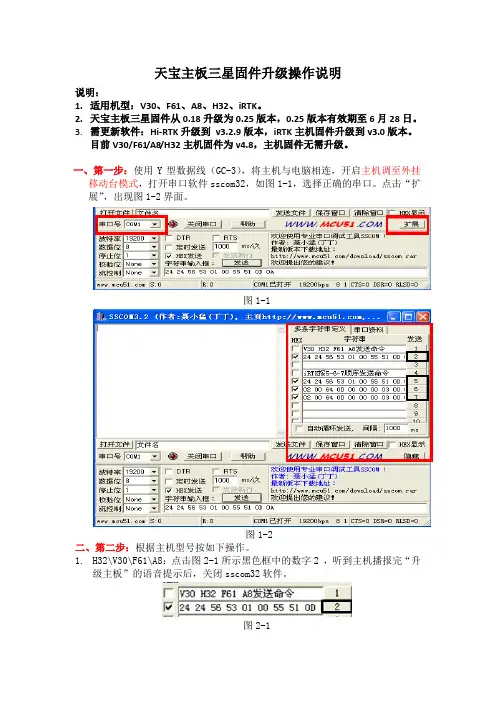
一、第一步:使用Y型数据线(GC-3),将主机与电脑相连,开启主机调至外挂移动台模式,打开串口软件sscom32,如图1-1,选择正确的串口。
点击“扩展”,出现图1-2界面。
图1-1图1-2二、第二步:根据主机型号按如下操作。
1.H32\V30\F61\A8:点击图2-1所示黑色框中的数字2,听到主机播报完“升级主板”的语音提示后,关闭sscom32软件。
图2-12.iRTK:按5-6-7顺序,点击图2-2所示黑色框中的数字,每次点击间隔1秒以上,5-6-7三条命令发送完后,关闭sscom32软件。
图2-2三、第三步:如您电脑上的串口为COM1,则直接跳到第四步。
否则按如下操作:右键单击,选“编辑”,出现如下所示:Dcom1为串口号,修改为电脑实际使用的串口,如您电脑上的串口是COM2,则将Dcom1改为Dcom2,然后点“文件->保存”后关闭文档即可。
四、第四步:双击UpdateBD970.bat",出现图4-1所示界面,正在升级固件,等待15分钟左右图4-1界面消失。
图4-1界面消失后,再等待5分钟即可完成固件升级,直接拔电池关机(升级主板固件时不支持电源键关机)。
图4-1五、第五步:验证固件是否升级成功。
开启主机,按键复位下主板,手簿连上主机。
如图5-1,数据板版本显示0.25表明升级成功,显示0.18表明升级失败。
如升级失败重启接收机从第一步开始重新升级。
图5-1。
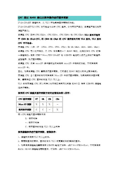
CPU 通过RS485 接口从软件操作进行固件更新S7-200 SMART 编程软件,从V2.3 开始具有固件更新的功能。
S7-200 SMART V2.3 CPU 系列包含十二种CPU 型号,分为两条产品线:紧凑型产品线和标准型产品线。
紧凑型CPU 四种: CPU CR20s、CPU CR30s、CPU CR40s 和CPU CR60s ,V2.3 版本不适用于CR40 和CR 60 CPU,即CR40 和CR60 的CPU 固件版本只到V2.2 版本,V2.3 版本CPU 中不包含。
标准型CPU 八种:ST (ST20、ST30、ST40、ST60 ) 和SR ( SR20、SR30、SR40、SR60 ) 紧凑型CPU 无以太网端口,仅CPU 本体集成一个RS485 端口,此端口作为CPU 的唯一编程端口。
使用STEP 7 Micro/WIN SMART 和USB-PPI 电缆可以进行上传和下载程序、监控程序、执行固件更新。
紧凑型CPU 没有microSD 读卡器或任何与使用microSD 卡相关的功能,不支持使用microSD 卡。
因此,如果紧凑型CPU 需要进行固件更新,仅可通过RS485 端口从软件上操作完成。
标准型CPU 各个固件版本均支持使用Micro SD 卡进行固件更新;如果使用软件固件更新,需要保证CPU 固件版本在V2.3 及以上。
V2.3 版本标准型CPU ,可以支持以太网端口使用网线或者RS485口使用USB-PPI 编程电缆进行更新。
使用的CPU类型及固件更新方法对应情况如表1.所示:表1.CPU类型及固件更新方法X:表示支持-- : 表示不支持C : 表示固件版本在V2.3 及以上支持使用编程软件进行固件更新,前提条件:1、编程软件使用V2.3及以上版本。
2、要更新固件的硬件,固件版本为V2.3 或更高版本的模块的固件。
3、如果使用编程电缆需要使用USB-PPI电缆,订货号:6ES7 901-3DB30-0XA0;不支持使用RS232 / RS 485编程电缆更新固件,订货号:6ES7 901-3CB30-0XA0。
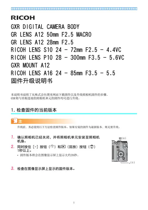
GXR DIGITAL CAMERA BODYGR LENS A12 50mm F2.5 MACROGR LENS A12 28mm F2.5RICOH LENS S10 24 - 72mm F2.5 - 4.4VC RICOH LENS P10 28 - 300mm F3.5 - 5.6VC GXR MOUNT A12RICOH LENS A16 24 - 85mm F3.5 - 5.5固件升级说明书本说明书说明了从株式会社理光⽹站下载固件以及升级照相机固件的步骤。
GXR和与其相连接的照相机单元的固件均可进⾏升级。
检查固件的当前版本1.1.机⾝。
2.同时按住 [-] 按钮(1)和6(回放)按钮(1秒以上。
•固件版本将会在图像显⽰屏上显⽰⼤约20秒。
3.检查在图像显⽰屏上显⽰的固件版本。
•例如:固件的当前版本为V1.00时,版本将会如下所⽰,显⽰为[MAIN : V 1.00]:2.解压固件1.从株式会社理光⽹站下载固件。
2.双击下载的⽂件或者右键单击⽂件并选择[打开]。
⽂件的扩展名为“.exe”时,对话画⾯出现后点击“确定”。
•将会创建⽂件夹[GXR Update],⽽固件会被解压⾄⽂件夹[Firmware relX.XX(X.XX为版本号)]。
检查⽂件夹[Firmware relX.XX]中是否有以下⽂件。
•请将固件解压后⽣成的⽂件(参见以上⽂件清单)全部复制到SD记忆卡的根⽬录下。
-------- 机⾝ --------MAIN : V 1.00BKUP : V X.XX MONI : V X.XX ADJD : V X.XX EXTD : V X.XX CPU1 : V X.XX ST : XXXXXX CV : XXXXXX-------- 照相机单元 --------MAIN : V 1.00BKUP : V X.XX MONI : V X.XX ADJD : V X.XX EXTD : V X.XX CPU1 : V X.XX SH : XXXXXX CV : XXXXXXilaunch0 ilaunch3 ilaunch4 ilaunch8jlaunch0 jlaunch3 jlaunch4 jlaunch8klaunch0 klaunch3 klaunch4 klaunch8nlaunch0 nlaunch3 nlaunch4 nlaunch8qlaunch0 qlaunch3 qlaunch4 qlaunch8l08firm0 l08firm3 l08firm4 l08firm8l06firm0 l06firm3 l06firm4 l06firm5 l06firm83.将固件复制到SD记忆卡上请准备64MB以上容量的SD记忆卡。
How ToUpdate Firmware on Hirschmann Switches This manual is only intended for use with Hirschmann Platform devices: ∙RS20/30/40∙RSR20/30∙MS20/30∙PowerMICE∙MACH100/1000/4000∙OCTOPUSTable of Contents1. Update firmware using HiView (2)1.1. Open HiView (2)1.2. Upload new software (3)1.3. Activate the new firmware (6)2. Update firmware using TFTP (9)2.1. Prepare TFTP-server (9)2.2. Start TFTP-update from telnet (10)2.3. Monitor TFTP-upload process (12)3. Update firmware using ACA21 (13)3.1. Manual update (13)3.2. Automatic update (16)1.Update firmware using HiView1.1.Open HiViewOpen HiView and type the IP address of the switch into the URL field and press Enter. If you do not have HiView, download the latest version from the Hirschmann US FTP site.ftp:///INET-IndustrialNetworking/Software/HiView/Once the device has loaded, a login screen appears.To be able to upload new firmware, log in with administrative rights. For a new switch, use the default values of:Login: admin (=default)Password: private (=default)Language: EnglishAfter a successful login, HiView opens the “Basic Settings > System” page. The “Basic Module” field shows the model of the switch that is targeted for update (MACH1040 in this instance).1.2.Upload new softwareIf you do not already have the firmware you wish to load, download the appropriate version from the Hirschmann US FTP site.ftp:///INET-IndustrialNetworking/Firmware/The download package will be a ZIP archive, so extract the archive to see its contents. The package contains several different files; it i s crucial to select the correct one. On the “Basic Settings > Software” page, note the “Running Version” of software. Note whether the software is Layer 2 (L2) or Layer 3 (L3), as well as whether it is Enhanced (E) or Professional (P). In our case, the switch is running L2P, or Layer 2-Professional.Click the “…” button in the “Software Update” section.A file selection window pops up. Search for and select the correct firmware file for the switch. With the file selected, click “Open”.The full file path is automatically added to the File field.Start the update process b y clicking the “Update” button.During the file upload, the window is grayed out, and a “Please wait …” pop-up message is shown.Wait un til the “Please w ait …” window is replaced wi th an “Update completed successfully.”popup.Confirm with “OK”.C lick on “Reload” to check the “Stored and Running Version”.1.3.Activate the new firmwareA “Cold Start” is required to activate the newly uploaded firmware.Go to the “Basic Settings > Restart” page and click on “Cold Start”.Confirm with “OK”.The switch reboots, and the HiView session is interrupted.The session may be reloaded by going to “File > Login screen” menu after about 2 minutes. Go to the “Basic Settings > Software” page to ensure both the Stored and Running Versions show the latest firmware version.2.Update firmware using TFTP2.1.Prepare TFTP ServerFor a TFTP update, a TFTP server is required to store the firmware file. TFTP stands for Trivial File Transfer Protocol.In this document, the freeware program “Tftpd32” or “Tftpd64”– from Ph. Jounin, a free download from /– is used to run a TFTP server on the PC where the firmware file is located.If you do not already have the firmware you wish to load, please see Section 1.2 for download details.Start the “tftpd32.exe” (or “tftpd64.exe”) program.If your PC has multiple network cards, be sure to select the correct “Server interface” – the IP address should be in the same subnet as the switch.Change the “Current Directory” to the folder where the firmware file can be found. You can use the “Browse” button to accomplish this.Search for the folder that contains the “.bin” file for the update.Confirm with “OK”.To be sure the desired firmware file is available in the selected directory; click “Show Dir” in the main program window.Minimize the TFTP server window (do not close the TFTP server program).2.2.Start TFTP update from telnetSetup a TFTP server as described in Section 2.1.Start a telnet session using your favorite application (e.g. HyperTerminal, PuTTY, etc.).In our example the TFTP server has the IP address 192.168.3.99, and the switch has the IP address 192.168.3.2. The following graphic shows a sample telnet session. Required input and user command examples are marked in red.The switch reboots, and the telnet session is interrupted.To check the results of the upgrade and for further configuration, log in to the switch using HiView after about 2 minutes.2.3.Monitor TFTP-upload processDuring the upload, the progress can be monitored by viewing the Tftpd program window.Both the “Tftp Server” and “Log viewer” tabs contain progress information.After the file is completely transferred, it still takes some time to write the software file to flash.3.Update firmware using ACA213.1.Manual updateThis method requires an ACA21 or any other compatible USB-stick, and local serial communication through the V24-connector.PreparationIf you do not already have the firmware you wish to load, please see Section 1.2 for download details.The desired firmware .bin file must be copied to the root directory of the USB. If it is placed in a subfolder, the switch will not recognize it.Plug the USB-stick into the switch you want to update.Connect the V24 socket with the XMODEM cable to your PC.Open a terminal session (V24.ht) with a HyperTerminal program.Press Return to connect to the switch.Update processPull the power plug to shut down the switch.Put the power plug back in to boot the switchAttention: quickly press “1” after the reboot (30 sec span) to cause the “System Monitor” menu to appear.Select “Update Operating System” by typing “2”.Complete the line with the path to the firmware file name and location.Add /usb0/{ firmware file name .bin }In our example /usb0/rsl2p.binConfirm 2 times by pressing “Return”.The firmware file is then uploaded, checked for errors, written to flash, and checked again.Only after the stat ement “Hit any key to continue” appears, the file has been transferred successfully.Hit any key to continue. The System Monitor menu will reappear.Choose “4 End (reset and reboo t)” by pressing “4“. The switch will reboot. This completes the update process.You can now close all program, disconnect the XMODEM cable and the ACA21 USB-stick. To check the results of the upgrade and for further configuration, log in to the switch using HiView.3.2.Automatic updateThis method only works if the running firmware is v6.x or higher.If you do not already have the firmware you wish to load, please see Section 1.2 for download details.The desired firmware .bin file must be copied to the root directory of the USB. If it is placed in a subfolder, the switch will not recognize it. The update will be executed even if the version on the stick is older than the current running version.Name the file according to the device and software variant (e.g. “rsL2P.bin” for an RS20). This operation is case sensitive.Create an additional empty file in the root directory of the USB-stick and name it “autoupdate.txt”.Plug the USB-stick into the switch targeted for update and reboot it.The switch will automatically update and perform a Cold Start afterwards.To check the results of the upgrade and for further configuration, log in to the switch using HiView.。
版权所有,不得翻印Copyright © 2008-2020 AURALIC LIMITED (AURALiC) and licensors.版权所有。
本出版物的任何部分,包括但不仅限于图片,文字,代码与交互功能,未经声韵音响(AURALiC)或其授权人的书面许可,不得复制。
本手册仅作提供信息之用,而不应被视为一种承诺。
声韵音响(AURALiC)有权对各种细节进行变更,不必另行通知。
声韵音响(AURALiC)对可能出现在本手册中的错误不承担责任。
AURALiC, inspire the music, Lightning DS, Lightning Streaming, Tesla Processor, Proteus Co-Processor, Purer-Power, Smart-IR, Unity Chassis, Unity Chassis II, ORFEO 以及它们的图标是声韵音响(AURALiC)的注册商标。
这些商标或商业外观不得以任何可能引起消费者混淆的方式,或任何贬低、诽谤声韵音响(AURALiC)的方式用于与本网站以及声韵音响(AURALiC)无关的任何产品或服务上。
本网站上的非声韵音响(AURALiC)持有的商标,是其商标权利人所独有的财产,这些权利人可能与本网站有相应的关系,或由声韵音响(AURALiC)所赞助。
未经声韵音响(AURALiC)或相关商标所有人的书面许可,本网站上的任何内容都不应被解释为以默许或其他方式授予许可而使用本网站上出现的商标的权利。
我们推出了旗舰升频处理器——SIRIUS G2.1。
作为一台专业的增强型机型,SIRIUS G2.1是屡获殊荣的AURALiC G2.1系列的第四款产品。
ARIES G2.1、VEGA G2.1、LEO GX.1和SIRIUS G2.1作为一套系统代表了现在世所可及的先进的数字音源其中之一。
无论是高码率的母带音乐还是来自劣等音源和格式的低质量音乐,均可通过SIRIUS G2.1改善并优化。
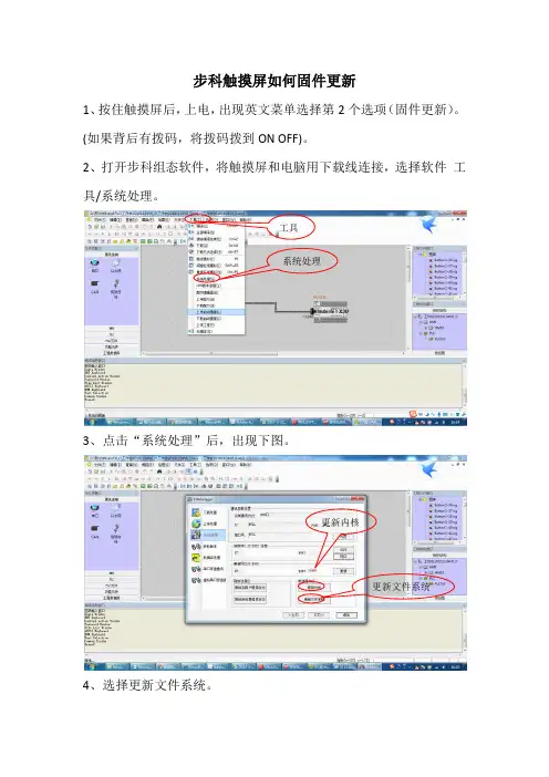
XC-PLC固件升级帮助文档
进行XC-PLC固件升级,会导致PLC中的用户程序丢失,应确保PLC中的用户程序已被保存。
XC-PLC固件升级过程如下:
1、运行升级工具
运行“XC系列PLC固件升级工具.exe”。
打开PLC固件文件(后缀名.sys)。
2、设置参数
XC3系列机型(包括XP系列机型),按照如下参数设置(串口号按照实
际连接设置):
更新到v2.3的参数为:6C000,10034,10035,0C000,1DFFF
更新到v2.5的参数为:6A000,10034,10035,0A000,1DFFF
V3.0以上版本,仅仅需要设置串口。
XC5系列机型,按照如下参数设置(串口号按照实际连接设置):
更新到v2.3的参数为:64000,30034,30035,24000,3DFFF
更新到v2.5的参数为:64000,30034,30035,24000,3DFFF
V3.0以上版本,仅仅需要设置串口。
3、下载
点击“下载”菜单项,出现如图显示:
4、PLC断电,将PLC与电脑通过编程电缆连接,XC1,XC2需要接1个短
接片,XCM需要接2个短接片,XC3,XC5不需要短接片。
5、PLC重新上电,可看到正在升级,如图显示:
6、等待升级完毕,升级完毕时,如图显示:
7、PLC重新上电,XC-PLC固件升级完毕。
(注意:升级过程中勿断电)
8、XC1,XC2,XCM升级完毕以后请取下端接片,重新上电,以防止电池耗
尽。
深圳市潮流网络技术有限公司GXV34X0系列企业级(高端)高清视频话机用户手册技术支持深圳市潮流网络技术有限公司为客户提供全方位的技术支持。
您可以与本地代理商或服务提供商联系,也可以与公司总部直接联系。
地址:深圳市南山区科技园高新北区酷派大厦C座14层邮编:518057网址:客服电话:*************客服传真:*************技术支持热线:4008755751技术支持论坛:/forums网上问题提交系统:/support/submit-a-ticket商标注明和其他潮流网络商标均为潮流网络技术有限公司的商标。
本文档提及的其他所有商标或注册商标,由各自的所有人拥有。
注意由于产品版本升级或其他原因,本文档内容会不定期进行更新。
除非另有约定,本文档仅作为使用指导,本文档中的所有陈述、信息和建议不构成任何明示或暗示的担保。
更改日志这一部分记录了GXV34X0用户指南以前版本的重大变化。
这里只列出了主要的新特性或主要的文档更新。
修改或编辑的次要更新没有记录在这里。
固件1.0.1.6版产品名称:GXV3480/GXV3450这是初始版本。
固件版本1.0.0.6产品名称:GXV3470这是初始版本。
目录欢迎 (10)产品概述 (10)功能亮点 (10)技术规格 (11)入门 (18)设备包装 (18)GXV34X0外观介绍 (20)连接和设置GXV34X0 (28)使用话机支架 (28)使用插槽安装在墙上 (29)连接GXV34X0 (30)清理话机 (31)了解GXV34X0 (32)使用触摸屏 (32)使用桌面 (34)桌面菜单 (34)添加小工具到桌面 (35)管理桌面项目 (35)设置壁纸 (37)设置可编程的关键部件 (37)可编程键状态 (38)管理运行的应用程序 (41)空闲屏幕 (41)设置主屏幕 (42)添加/删除空闲屏幕 (43)使用状态栏 (44)状态栏中的通知 (46)使用GXV34X0按键 (48)截图 (50)硬复位 (50)使用屏幕键盘 (51)消息指示灯 (52)拨打电话 (53)注册SIP帐户 (53)帐户状态 (53)配置SIP帐户 (53)直接拨号 (54)重拨 (55)使用通讯录拨打电话 (55)通过通话记录拨号 (56)接听电话 (57)单一来电 (57)来电转移 (58)呼叫进展状态 (59)呼叫保持 (60)静音 (61)视频通话转成语音通话 (61)通话时切换音频频道 (62)呼叫转接 (63)指定转接 (64)通过MPKs转移 (65)设置虚拟背景 (66)多方会议 (67)启动会议 (67)删除会议成员 (69)结束会议 (69)保持和恢复会议 (70)多播分页 (70)多播监听开关 (70)UCM会议 (71)加入UCM会议室 (71)电话会议菜单 (71)未接来电 (72)免打扰(DND) (73)呼叫功能 (76)联系人 (78)本地联系人 (78)添加单个联系人 (78)导入/导出联系人 (79)下载联系人 (81)查找联系人 (81)使用联系人 (82)通过联系人发起呼叫 (82)将联系人添加到收藏夹 (82)编辑联系人 (83)发送联系人快捷键到桌面 (83)通过蓝牙共享联系人 (83)添加黑名单 (84)添加分组 (84)将联系人添加到分组中 (84)联系人储存状态 (84)状态检测 (85)通用检测 (85)音频检测 (86)骚扰拦截 (87)拦截联系人 (87)拦截记录 (88)拦截匿名来电 (89)通话记录 (90)通话记录类型 (91)拨打通话记录 (91)通话记录选项 (91)删除通话 (91)GXV34X0用户手册版本号:1.0.1.66录音管理 (93)通话记录-录音 (93)录音 (94)录音设置 (94)文件管理器 (95)文件操作 (95)复制和粘贴文件 (95)移动文件 (96)分享文件 (96)删除文件 (97)文件重命名 (97)文件类别 (98)GS应用市场 (98)文件传输服务器 (98)行动网址 (101)连接GXV34X0到门禁系统 (101)网络及设备连接 (102)网络 (102)Wi-Fi (102)打开/关闭Wi-Fi (102)连接Wi-Fi (103)Wi-Fi设置快捷方式 (104)蓝牙 (105)打开/关闭蓝牙 (105)与蓝牙设备配对 (106)取消蓝牙配对 (106)蓝牙快捷设置 (107)EHS耳机 (107)USB耳机 (108)紧急呼叫 (109)体验GXV34X0话机 (111)表目录表1:GXV34X0特性一览表 (11)表2:GXV3480技术规格 (13)表3:GXV3470技术规范 (15)表4:GXV3450技术规范 (17)表5:GXV3480设备包装 (21)表6:GXV3480后视图 (21)表7:GXV3480侧视图 (22)表8:GXV3470前视图 (23)表9:GXV3470后视图 (24)表10:GXV3470侧视图 (24)表11:GXV3450前视图 (26)表12:GXV3450后视图 (27)表13:可编程键状态说明 (40)表14:GXV34X0状态栏通知图标 (48)表15:GXV3480和GXV3470按键 (49)表16:GXV3450按键 (50)表17:GXV34X0LED状态 (53)表18:GXV34X0功能代码 (77)图目录图1:GXV3480包装内容 (18)图2:GXV3470包装内容 (19)图3:GXV3450包装内容 (20)图4:GXV3480正视图 (20)图5:GXV3480后视图 (21)图6:GXV3480侧视图 (22)图7:GXV3470前视图 (22)图8:GXV3470后视图 (23)图9:GXV3470侧视图 (24)图10:GXV3450前视图 (25)图11:GXV3450-GBX20扩展模块前端 (25)图12:GXV3450后视图 (26)图13:GXV3480话机支架 (28)图14:GXV3470话机支架 (28)图15:GXV3450话机支架 (29)图16:GXV3480壁挂 (29)图17:GXV3470壁挂 (30)图18:GXV3450壁挂 (30)图19:GXV3480背视图 (31)图20:GXV34X0默认桌面 (32)图21:应用程序 (33)图22:GXV34X0屏幕上的手指手势图 (33)图23:GXV3470桌面菜单 (34)图24:将小工具添加到桌面 (35)图25:打开时钟工具 (36)图26:调整工具大小 (36)图27:GXV34X0更换壁纸 (37)图28:可编程关键部件 (38)图29:可编程键页面 (38)图30:GXV34X0最近的应用 (41)图31:GXV34X0切换空闲屏幕 (42)图32:设置主屏幕 (43)图33:添加一个空闲屏幕 (43)图34:删除一个空闲屏 (44)图35:GXV34X0顶部状态栏 (44)图36:状态栏-更多选项 (45)图37:GXV34X0状态栏-获取更多信息 (45)图38:GXV34X0状态栏-Wi-Fi (46)图39:GXV3480按键 (48)图40:GXV3470按键 (49)图41:GXV3450按键 (49)图42:GXV34X0英文键盘 (51)图43:GXV34X0小写和大写 (51)图44:英文键盘-数字和符号 (52)图45:英文键盘-更多符号 (52)图46:GXV34X0帐户小工具 (53)图47:GXV34X0拨号屏幕 (54)图48:GXV34X0通讯录 (55)图49:GXV34X0通话记录 (56)图50:从通话记录中选择通话模式 (56)图51:单个来电-音频 (57)图52:单个来电-视频 (58)图53:单个来电转移-1 (58)图54:单个来电转移-2 (59)图55:呼叫等待 (59)图56:触摸返回通话界面 (60)图57:呼叫保持 (60)图58:通话录音 (61)图59:通话静音 (61)图60:视频转成音频 (62)图61:语音通话中收到视频请求 (62)图62:通话期间切换声音通道 (63)图63:盲转 (64)图64:指定转接 (64)图65:通过MPK转移 (65)图66:MPK列表 (66)图67:设置虚拟背景 (67)图68:在拨号界面添加会议成员 (68)图69:从拨号界面中添加会议号码 (68)图70:GXV34X0会议界面 (69)图71:开启多播对讲监听 (71)图72:加入UCM会议室 (71)图73:会议菜单选项 (72)图74:未接来电显示 (72)图75:启用/禁用免打扰 (73)图76:查看语音邮件 (74)图77:呼叫转移类型 (75)图78:呼叫转移–无条件 (75)图79:呼叫转移-时间 (75)图80:呼叫转移–忙线/无应答/免打扰 (76)图81:GXV34X0联系人 (78)图82:GXV34X0联系人–添加联系人 (79)图83:GXV34X0联系人–导入联系人 (80)图84:GXV34X0联系人–导出联系人 (80)图85:GXV34X0联系人-下载联系人 (81)图86:GXV34X0联系人–查找联系人 (82)图87:添加联系人到收藏夹 (83)图88:GXV34X0联系人–储存状态 (85)图89:GXV3480端口和网络状态 (86)图90:扬声器检测 (86)图91:麦克风检测 (87)图92:黑名单 (87)图93:拦截记录 (88)图94:手动添加黑名单 (89)图95:拦截匿名来电 (90)图96:GXV34X0通话记录 (90)图97:GXV34X0通话记录-选项 (91)图98:GXV34X0通话记录详情 (92)图99:通话记录-录音 (93)图100:录制音频 (94)图101:录音设置 (95)图102:文件管理器–复制文件 (96)图103:文件管理–分享 (97)图104:文件传输服务-开启 (99)图105:文件传输服务-停止 (99)图106:FTP服务器设置 (100)图107:GXV34x0浏览器 (100)图108:来自GDS3710门禁系统的呼入电话 (101)图109:连接Wi-Fi (103)图110:连接Wi-Fi-显示高级选项 (104)图111:Wi-Fi–添加网络 (104)图112:Wi-Fi设置快捷方式 (105)图113:GXV34X0蓝牙–配对设备 (106)图114:蓝牙快捷设置 (107)图115:EHS耳机 (108)图116:使用USB耳机通话 (108)图117:GXV34X0连接USB存储设备 (109)图118:Web界面设置紧急号码 (109)图119:紧急呼叫 (110)GXV34X0用户手册版本号:1.0.1.610欢迎感谢您购买潮流网络GXV34X0企业级(高端)高清视频电话。
Dear Customer√About the Upgrade of the DMC-G2 FirmwareThe following functions were added or changed from Ver.1.1 of the firmware.Please read this in conjunction with the operating instructions for the camera.•The firmware version can be checked from the [VERSION DISP .] of the [SETUP] menu.Attaching the 3D interchangeable lens (H-FT012; optional) to the camera allows you to take 3D pictures for extra impact.To view 3D pictures, a television that supports 3D is required.Attach the 3D interchangeable lens to the camera.Bring the subject into the frame and record by pressing the shutter button fully.•Focusing is not required when recording 3D pictures.•Still pictures recorded with the 3D interchangeable lens attached are saved in MPO format (3D).Note•You cannot record 3D pictures in vertical orientation.•It is recommended to use a tripod or a flash to record steady pictures.•When a distance to the subject is 0.6m (1.97feet) to approximately 1m (3.28feet), horizontal disparity becomes too great, and you may not see the 3D effect at the edges of the image.•Up to approx. 650 3D pictures can be recorded on a 2GB card. (When the aspect ratio is set to[X ], and the quality is set to [].)•Using the 3D interchangeable lens darkens the camera optics and so the automatically adjusted ISO sensitivity may be set higher than normal.•Read the operating instructions of the 3D interchangeable lens for details.For 3D recording/viewing, also read the “Cautions for Use” in the 3Dinterchangeable lens operating instructions.We have added a function for recording 3D pictures.To ensure that the 3D pictures can be safely viewed, pay attention to thefollowing points when recording.•Where possible, record with the unit in a horizontal state.•The suggested minimum subject distance is 0.6m (1.97feet).•Be careful not to shake the camera while in a vehicle or walking.VQC8287ENGLISHVQC82872∫Functions that cannot be used during 3D recordingWhen recording with the 3D interchangeable lens (H-FT012; optional), the following feature will be disabled:(Recording functions)•Auto Focus/Manual Focus operation•Aperture setting•Zoom operation•Recording motion pictures ¢1•[DYNAMIC ART] in My Color Mode¢1The motion picture button, Motion Picture P Mode and the [MOTION PICTURE] Mode menuwill be unavailable or unusable.([REC] Mode menu)•[PICTURE SIZE]¢2/[QUALITY]¢3/[STABILIZER]/[RED-EYE REMOVAL]/[I.RESOLUTION]/[I.EXPOSURE]/[EX.OPT.ZOOM]/[DIGITAL ZOOM]/[AUDIO REC.]¢2The setting is fixed as shown below.¢3When attaching 3D interchangeable lens, the following icons are displayed.([CUSTOM] menu)•[AF/AE LOCK]/[PRE AF]/[DIRECT FOCUS AREA]/[FOCUS PRIORITY]/[AF ASSIST LAMP]/[AF+MF]/[MF ASSIST]/[MF GUIDE]/[BUTTON]/[REC AREA]/[REMAINING DISP .]Connecting the camera to a 3D compatible television and playing back pictures taken in 3D allows you to enjoy 3D pictures for extra impact.It is also possible to play back the recorded 3D pictures by inserting an SD card into the 3D compatible television with an SD card slot.Aspect ratioPicture size X1600k 1200pixels Y1600k 1064pixels W 1600k 904pixels1440k 1440pixels[]:MPO i Fine (Both MPO images and fine JPEG images are recorded simultaneously.)[]:MPO i Standard (Both MPO images and standard JPEG images are recordedsimultaneously.)We have added a function for playing back 3D pictures.•[3D PLAYBACK] has been added to the [SETUP] menu.•[2D/3D SETTINGS] has been added to the [PLAYBACK] menu.(This is a menu that is only displayed when 3D display is possible.)•[3D] has been added to the [SLIDE SHOW] of the [PLAYBACK] menu.•[3D PLAY] has been added to the [PLAYBACK MODE] of the [PLAYBACK] menu.3VQC8287Set the [3D PLAYBACK] in the [SETUP] menu to [].Connect the camera to a 3D compatible television using an HDMI mini cable (optional) and press [(].•For the pictures recorded in 3D, [] will appear on the thumbnail display at playback.•When [VIERA Link] in the [SETUP] menu is set to [ON] and the camera is connected to a TV supporting VIERA Link, input of the TV will be switched automatically and playback screen will be displayed.When using the VIERA Link, you can perform operations using the television remote control.–At multi-playback, if you selected the [] tab, only the still pictures recorded in 3D will be displayed.–At One screen display, each press of 3 on the television remote control will switch between 2D playback and 3D playback. (only when 3D playback is available)To display the recording information, press the [SUB MENU] button and select to switch to recording information.–During 3D playback, the Slide show settings screen cannot be displayed.∫Playback in 3D by selecting only the still pictures recorded in 3DSelect [3D PLAY] in [PLAYBACK MODE] in the [PLAYBACK] Mode menu.∫Playback as a 3D slide show by selecting only the still pictures recorded in 3D Select [3D] in [SLIDE SHOW] in the [PLAYBACK] Mode menu.∫Switch the playback method for the still pictures recorded in 3D1Select the picture recorded in 3D.2Press [MENU/SET] to display the menu.3Select [2D/3D SETTINGS] on the [PLAYBACK] Mode menu and then press 1.•Playback method will switch to 3D if it is playing back in 2D (conventional image), or it will switch to 2D if it is playing back in 3D.•If you feel tired, uncomfortable or otherwise strange when playing back pictures recorded in 3D, set to 2D.For the latest information on 3D compatible televisions and recorders that are capable of playing back 3D pictures recorded using the unit, see the support site below.http://panasonic.jp/support/global/cs/dsc/ (This Site is English only.)Preparations:Set the [HDMI MODE] in the [SETUP] menu to [AUTO] or [1080i].[]:Set when connecting to a 3D compatible television.[]:Set when connecting to a television not compatible with 3D.Set this when you would like to view pictures in 2D (conventional image) ona 3D compatible television.VQC82874∫Functions that cannot be set/do not work with 3D pictures•[HIGHLIGHT] in the [CUSTOM] menu ¢•Playback Zoom ¢•Deleting pictures ¢•Editing functions of [PLAYBACK] Mode menu ([TITLE EDIT]/[TEXT STAMP]/[VIDEO DIVIDE]/[RESIZE]/[CROPPING]/[ASPECT CONV.]/[ROTATE]/[ROTATE DISP.]/[FAVORITE]¢/[PRINT SET]¢/[PROTECT]¢/[FACE REC EDIT]¢)¢Can be used when displayed in 2D.Note•When a picture recorded in 3D is displayed on the LCD monitor/viewfinder of this unit, it is played back in 2D (conventional image).•A black screen is displayed for a few seconds when switching back and forth playback of 3D pictures and 2D pictures.•When you select a 3D picture thumbnail, it may take a few seconds for playback to start. After playback, the thumbnail display may take a few seconds to reappear.•When viewing 3D pictures, your eyes may become tired if you are too close to the television screen.•If your television does not switch to a 3D picture, make the necessary settings on the TV. (For details, refer to the operating instructions of the TV.)∫Saving 3D picturesYou can save 3D pictures using a recorder or a computer.Dubbing with a recorder3D pictures will be recorded in MPO format when copied with the 3D compatible recorder.•When the copied pictures do not playback in 3D, perform the necessary setup on the television. (For details, refer to the operating instruction of the television.)•Note that the equipment described may not be available in certain countries and regions.Copying to a PCIf you update the supplied “PHOTOfunSTUDIO 5.0 HD Edition” software to the latest version, it will be able to handle MPO format still pictures recorded using the camera.Check the latest information about the equipment that can copy on the following website.http://panasonic.jp/support/global/cs/dsc/ (This Site is English only.)For details on how to update the software, refer to the following website.http://panasonic.jp/support/global/cs/dsc/ (This Site is English only.)。
RELEASE NOTES 1.2.0 | June 2020 | 3725-32916-003A Poly G200ContentsWhat’s New (2)Release History (3)Security Updates (4)Supported Browsers (4)Products Tested with This Release (4)System Constraints and Limitations (5)Resolved Issues (6)Known Issues (7)Get Help (9)Privacy Policy (10)Copyright and Trademark Information (10)PLANTRONICS + POLYCOMNOW TOGETHER AS POLY 1What’s NewPoly G200 1.2.0 includes the features and functionality of previous releases and includes the following new features.Poly Studio USB Video Bar SupportPoly G200 1.2.0 supports the Poly Studio USB video bar as the system’s camera, microphone, and speakerphone. You can configure the camera settings from the G200 system web interface.The Poly Studio remote control can mute, answer, or end a call.Note: To avoid conflicts between peripherals, d on’t use Poly Studio with another USB camera or a headset.HDMI as Camera Input (AVC only)You can configure the G200 camera settings to use the HDMI input as the video input and still share content from the Polycom Content App. You can also connect an HDCI camera to the HDMI port on your G200 system using the following accessories:•Polycom RealPresence Digital Breakout, camera adapter (part number: 3820-68485-001)•Polycom power supply (part number: 1465-52748-040)The G200 system only accepts one type of video input. You can choose to use HDMI or USB on the Camera Settings page.Turning On/Off Camera Tracking from the Remote ControlDuring a call, you can press the Menu button on the remote control to display the meeting control panel. From there, you can enable or disable the camera tracking feature.USB Headset SupportYou can use a wired or wireless USB headset for your system’s audio input and output with Poly G200 1.2.0. Once enabled, the headset becomes the primary audio device of your G200 system.Supported USB headsets:•Plantronics Blackwire 3210 USB-A•Plantronics Blackwire 3220 USB-A•Plantronics Blackwire 5210 USB-A•Plantronics Blackwire 5220 USB-A•Plantronics Voyager 3200 UC•Plantronics Voyager 4220 USB-A•Plantronics Voyager 5200 UC•Plantronics Voyager Focus UC Bluetooth•Plantronics Voyager 6200 UCPerformance Enhancement in SVC ModePoly G200 1.2.0 adopts SirenLPR-64 support in SVC mode for better network resiliency, as well as dynamic bandwidth detection and allocation of both downlink and uplink for better user experiences. More Display in SVC MeetingsYou can choose how to display the participants’ names in the meeting at System Settings > Call Settings > Display Name.A name card displays when there’s no video of a participant.Firewall or NAT TraversalPoly G200 1.2.0 supports basic firewall or network address translation (NAT) traversal in SVC mode. Meeting participants behind or outside the firewall can join the same SVC call via the Poly RealPresence Clariti Ensemble server.You can configure the ports at Admin Settings > NAT Settings.Release HistoryThis following table lists the release history of Poly G200.Release History1.2.0 May 2020 Support for Poly StudioSupport for HDMI as camera inputCamera tracking switch from the remote controlSupport for USB headsetsPerformance enhancement in SVC modeMore display options in SVC meetingsFirewall or NAT Traversal1.1.0 January 2020 Support of Poly EagleEye Cube USB cameraContent sharing from Polycom Content App in AVC modeProvisioning enhancementSVC conferencing and interoperability with Poly RealPresenceClariti Ensemble1.0.0 September 2019 Initial releaseSecurity UpdatesPlease refer to the Polycom Security Center for information about known and resolved security vulnerabilities.Supported BrowsersYou can access the G200 system web interface with the following browsers:•Google Chrome 79•Apple Safari 13.0.4•Microsoft Internet Explorer 11•Mozilla Firefox 71.0Products Tested with This ReleasePoly G200 systems are tested extensively with a wide range of products. The following list isn’t a complete inventory of compatible equipment. It indicates the products that have been tested for compatibility with this release.Note: Poly recommends that you upgrade your Poly devices with the latest software versions, as compatibility issues may already have been addressed by software updates. See the CurrentPolycom Interoperability Matrix to match product and software versions..Products Tested with This ReleasePolycom RealPresence Access Director 4.2.5 N/A10.0, 10.1 N/APolycom RealPresence Distributed MediaApplication (DMA)Polycom RealPresence DMA (edge configuration) 10.0 N/A8.7.5, 8.8.0, 8.8.1 N/APolycom RealPresence Collaboration Server (RMX)1800/2000/40008.8.0 N/APolycom RealPresence Collaboration Server, VirtualEdition8.5.13 N/APolycom RealPresence Collaboration Server2000/4000 with MPMx cardPolycom VBP 7301 Series 14.8.10 N/APolycom HDX series 3.1.14 N/APolycom RealPresence Desktop 3.10.2 N/AN/A Polycom RealPresence Mobile 3.10.1 (Android)3.11.1 (iOS)Polycom RealPresence Group Series 6.2.1, 6.2.2 N/APolycom RealPresence Web Suite 2.2.2 N/AHARMAN Media Suite 2.8.2 N/APoly RealPresence Clariti Ensemble N/A 1.1.0 Poly EagleEye Cube USB camera 1.2.0 1.2.0Poly EageEye Cube HDCI camera 1.0.1 N/APolycom EagleEye IV HDCI camera Group Series bundled N/APolycom EagleEye Mini USB camera 9.0.21 9.0.21 Polycom Content App 1.3.2 N/APoly Studio X30/X50 3.2.0 N/APoly G7500 3.0.1 N/APoly Studio 1.3.0 1.3.0 System Constraints and LimitationsThis section provides information on constraints and limitations when using Poly G200 1.2.0.Switching Between Monitor ModesPoly G200 doesn’t support switching between monitor modes by hot swapping (or hot plugging) HDMI output. If you plug a monitor in or out during a call, the system may not work correctly. For example, the layout retains single-monitor mode even if you plug in a second monitor.Monitor LimitationTo provide expected system performance, your monitor must have built-in speakers and support 1080p. For some monitors that don’t support the Consumer Electronics Control (CEC) function, after you wake up the G200 system, use the monitor remote control to wake up the monitor manually.Content LimitationPoly G200 doesn’t support H.263 content in H.323-based or SIP-based meetings. To avoid issues, Poly suggests setting the content protocol to H.264 only or enabling content transcoding in the conference template of your MCU or media application device.Single Camera LimitationPoly G200 only supports one USB camera at a time. If you connect two cameras to the G200 system, the video output may not work properly. If you experience video issues, you must unplug one camera and reboot the system.HDMI Video InputIf you connect a camera via the HDMI port and configure it as the video input, you can’t control the camera or change the camera’s resolution. You may also need to reboot the system before the camera works properly.Video Color LimitationColor reproduction accuracy can vary based upon environmental conditions and camera sensor capabilities.Polycom RealPresence Mobile and Polycom RealPresence DesktopPoly G200 doesn’t support SmartPairing with RealPresence Mobile or RealPresence Desktop. Resolved IssuesThe following table lists the resolved issues in Poly G200 1.2.0.Resolved IssuesAudio EN-159029 1.1.0 Sometimes if you plug in the expansion microphone during a call oran audio meter test, it doesn’t pick up t he audio.Camera EN-163897 1.1.0 During a call, if you connect an outdated camera, the system can’tupgrade the camera after the call.Content EN-149372 1.0.0 In dual monitor mode, if you share 720p content then unplug theHDMI input and switch to 1080p content, the secondary monitordisplays a black screen.Content EN-164060 1.1.0 In an encrypted SIP meeting, if someone shares content while youhave shared content for more than 10 minutes, you see black screeninstead of the newly sent content.Network EN-176363 1.1.0 Sometimes G200 disconnects itself from Zoom meetings.Provisioning EN-164114 1.1.0 In SVC mode, if you modify any settings on the Call Settings orGeneral page of a provisioned G200 system, the provisioning statusbecomes unregistered.Software EN-148494 1.0.0 When you change the local interface language using the system webinterface, the following issues may happen:•The camera status shows as disconnected.•In dual monitor mode, the second monitor shows a blackscreen.In dual monitor mode, after you press the reset button, the screendoesn’t show the remote control pairing page.Upgrade EN-148306 1.0.0 If you connect the EagleEye Mini USB camera with an outdatedsoftware version to a sleeping G200 system, the upgrade d oesn’tstart automatically.Upgrade EN-148492 1.0.0 Occasionally, the upgrade process may get stuck at the reboot page.Video EN-148737 1.0.0 Sometimes during a P2P call between two G200 systems, the farend may see frozen video.Video EN-163193 1.1.0 Sometimes when the RealPresence Clariti Ensemble server isheavily loaded, the received video frame rate slumps and recovers ina few seconds.Known IssuesThe following table lists known issues in this release.Note: These release notes do not provide a complete listing of all known issues that are included in the software. Issues not expected to significantly impact customers with standard voice and videoconferencing environments may not be included. In addition, the information in these releasenotes is provided as-is at the time of release and is subject to change without notice.Known IssuesAudio EN-147361 When you use G200 with HDMI content sharing from aMac and reboot the G200 system while the HDMI inputcable is plugged in, the system audio switches to theMac instead of the monitor. Reconnect the monitor’s HDMI cable.Audio EN-161139 If you locate the monitor with an EagleEye Cube camerain a huddle room with a glass wall at the opposite side ofthe camera, due to complex reflections of sound, the farend hears echoes in calls.Relocate the camera.Audio EN-171902 During a meeting, if you play music near themicrophone, the audio quality at the other end drops. Turn down the volume of the music.Calling EN-179315 When using RealPresence Collaboration Server 2000running software version 8.8.1 and you host aconference with a Chinese language name,RealPresence Collaboration Server fails to dial out toG200 systems for AVC calls.Do one of the following: •Rename theconference using anEnglish name. •Use the G200system to dial in tothe conference.Camera EN-157938 Sometimes the local view is black when you use anEagleEye Cube USB camera. Reboot the camera. If the issue persists, reboot the G200 system.Content EN-147731 If you use a third-party DP-HDMI cable connecting theG200 system to a Mac, the screen may not showcontent after waking up and reconnecting the power.Reboot the system.Content EN-148522 If you send colorful Excel content in a meeting, thecontent may be blurry when you use the followingresolution rates:•720p15 content with 512 Kbps content rate•1080p15 content with 1024 Kbps content rate Wait one or two minutes until the content restores.Content EN-157200 When you send 1080p and 720p content in a 3 × 3layout during an SVC meeting, the content rate may notreach 30 fps.None.Content EN-162536 Sometimes the G200 system can’t send content and theCVTX frame rate in Call Statistics is zero.Reboot the system.Content EN-170719 In an SVC call at 512 Kbps, when the far end sharescontent, you still see the video instead of the content.Raise the call speed.Monitor EN-138834 Philips 220TS2LB monitors may not play audio fromG200 correctly. Reconnect the monitor’s HDMI cable.Monitor EN-147744 Samsung UA40HU5920J monitors can’t wake up fromsleeping.Reboot the monitor.Monitor EN-148739 In dual monitor mode, LG 42LD450C-CA monitors maynot work as the second monitor after the G200 systemwakes up from sleeping. Reconnect the monitor’s HDMI cable.Remote Control EN-163763 Sometimes when the remote control stays idle or sleepsfor a long time, it loses connection with the system.Re-pair the remotecontrol.Video EN-161901 In an AVC call using RealPresence Collaboration Server(RMX) 8.5, when you pause the video, the far end seesthe last frame of the video instead of the muted videopicture.None.Video EN-178544 When connected with Poly Studio, the video sometimesshows a black screen.None.Video EN-180375 In an SVC call, some networks with heavy jitters maycause video to become stuck briefly.None.Get HelpFor more information about installing, configuring, and administering Poly/Polycom products or services, go to the Poly Online Support Center.Related Poly and Partner ResourcesSee the following sites for information related to this product.●The Poly Online Support Center is the entry point to online product, service, and solution supportinformation including Video Tutorials, Documents & Software, Knowledge Base, CommunityDiscussions, Poly University, and additional services.●The Polycom Document Library provides support documentation for active products, services, andsolutions. The documentation displays in responsive HTML5 format so that you can easily access and view installation, configuration, or administration content from any online device.●The Poly Community provides access to the latest developer and support information. Create anaccount to access Poly support personnel and participate in developer and support forums. You can find the latest information on hardware, software, and partner solutions topics, share ideas, and solve problems with your colleagues.●The Poly Partner Network are industry leaders who natively integrate the Poly standards-basedRealPresence Platform with their customers' current UC infrastructures, making it easy for you to communicate face-to-face with the applications and devices you use every day.●The Polycom Collaboration Services help your business succeed and get the most out of yourinvestment through the benefits of collaboration.Privacy PolicyPoly products and services process customer data in a manner consistent with the Poly Privacy Policy. Please direct comments or questions to ****************.Copyright and Trademark Information© 2020 Plantronics, Inc. All rights reserved. No part of this document may be reproduced, translated into another language or format, or transmitted in any form or by any means, electronic or mechanical, for any purpose, without the express written permission of Plantronics, Inc.Plantronics, Inc. (Plantronics + Polycom, Now together as Poly)345 Encinal StreetSanta Cruz, California95060Poly and the propeller design are trademarks of Plantronics, Inc. All other trademarks are the property of their respective owners.。
夏新手机升级操作指南V1.6一、准备工作 (2)1、所需硬件和软件 (2)二、 Florance平台升级指导 (3)三 Vienna平台升级指导 (15)四、 EMP平台升级指导 (21)(一)、G200系列 (21)(二)、U100系列 (33)(三)、G100系列 (39)五、Motorola+Florance(E8)平台升级指导 (41)(一)、安装USB转串口数据线驱动(针对Win2000系统) (41)(二)、安装i.MX21 HAB ToolKits(针对Win2000系统) (41)(三)、FLORENCE升级部分(该软件不向客户公开) (45)六、Philips平台升级指导 (49)(一) E600手机升级方法 (49)(二) M635手机升级方法 (53)(三) M639手机升级方法 (54)七、E850升级指导 (58)(一)、基带Vienna平台程序的升级 (58)(二)、Bulverde平台程序的升级 (61)九、Vision平台 (65)十、TI平台升级指导 (71)1、DS6升级指导 (71)2、TI OMAP(E70) (85)3、Locosto (91)十一、SC6600系列 (100)十二、SC6800系列 (103)注:软硬件部分请参考客服系统上《夏新手机软硬件匹配指南》一、准备工作VJP05FI92001AmoiFlash通用miniUSB数据线SC66001302 0000 0018M300/M30/A628/A3+/F710/M3/M680DLoaderR.exe注意升级工具版本SC6800 A50/A51/A58/A5二、 Florance平台升级指导1、安装数据线驱动把数据线插入电脑的 USB口,电脑会弹出如下对话框,如图 1图 1单击“否,暂时不(T)”,然后单击“下一步(N)”继续,弹出如下对话框如图 2图 2单击“从列表或指定位置安装(高级)(S)”,然后单击“下一步(N)”继续,弹出如下对话框,如图 3图 3单击“在这些位置上搜索最佳驱动程序(S)”,然后点击“在搜索中包括这个位置(O)”,使得这句话前面的方框打上勾,再点击“浏览(R)”,出现如下对话,如图 4图 4由于在我电脑上文件夹“夏新手机升级说明文档及相关文件”是放在 D盘中的,上图的拓扑结构是通过点击“本地硬盘(D:)”前的+号,然后再点击文件夹“夏新手机升级说明文档及相关文件”得到的,最后点击“数据线驱动”文件夹,也就是使得“数据线驱动”文件夹的背影为深蓝色。
固件升级说明书
本说明书说明了从株式会社理光网站下载GX200固件以及升级照相机固件的步骤。
执行以下操作,进行固件升级。
1. 检查固件版本
升级前,务必使用以下方法检查固件版本。
如果安装的固件为最新版本,则无需升级。
1.确保照相机的电源已关闭,并将模式转盘切
换至SCENE(场面模式)。
2.同时按住N(超微距)按钮和6(回放)按
钮2-3秒。
•固件版本将会在图像显示屏上显示大约20秒。
3.检查在图像显示屏上显示的固件版本。
•例如:固件版本为V1.00时,版本将会如下所示,
显示为[MAIN : V 1.00]:
MAIN :V 1.00
BKUP :V X.XX
MONI :V X.XX
ADJD :V X.XX
EXTD :V X.XX
CPU1 :V X.XX
SH :XXXXXX
ST :XXXXXX
6(回放)按钮模式转盘
2. 解压固件1.从株式会社理光网站下载固件。
2.双击下载的文件或者右键单击文件并选择[打开]。
•将会出现一个对话框。
3.
单击[确定]。
•将会创建文件夹[GX200 Update],而固件会被解压至文件夹[Firmware relX.XX(X.XX为版本号)]。
检查[claunch3](固件文件)和[claunch8](调整值文件)是否在文件夹[Firmware relX.XX]中。
3. 将固件复制到SD记忆卡上
有两种方法可将固件复制到SD记忆卡上。
•在照相机上插入一张SD 记忆卡,用附带的USB 连接线连接照相机和电脑,然后将固件复制到SD 记忆卡上。
•使用卡片阅读器或卡片写入器将固件复制到SD记忆卡上(需要卡片阅读器或卡片写入器)。
通过USB连接线连接照相机和电脑来复制固件
1.如果您的Windows PC上安装了Caplio 软件,请确认未启动RICOH Gate La。
2.如果正在使用RICOH Gate La,请在工具栏中使用右键单击RICOH Gate La,然后单击[退出]。
•如果工具栏中没有显示RICOH Gate La图标,则无需执行步骤2。
3.为照相机装上一个有足够电量的电池。
4.在照相机上插入SD记忆卡,并开启电源。
5.
在显示的照相机设定菜单上选择[格式化[插卡]],然后按下$按钮。
claunch3claunch8
claunch3claunch8
Windows操作系统
Macintosh操作系统
6.
选择[是],然后按下MENU/OK按钮。
•
SD记忆卡被格式化。
对记录图像的插卡进行格式化后,所有内容将会消失。
格式化插卡前,将那些您不想删除的图像保存至您的电脑上。
7.
关闭照相机,并用附带的USB连接线连接照相机和电脑。
•照相机将自动开启。
如果照相机没有自动开启,请按下POWER按钮开启电源。
•如果您的Windows PC上安装了Caplio软件,RICOH Gate La可能会自动开启。
若出现这种情况,请退出RICOH Gate La。
•如果Windows XP或Windows Vista中出现了[可移动磁盘]对话框,请单击[取消]。
•如果iPhoto在Mac OS X中开启,请退出iPhoto。
8.
将文件[claunch3]和[claunch8](解压固件时创建)复制到[我的电脑]中的[RICOHDCX]上。
•照相机的驱动器名称可能会因您所使用的操作系统而异。
例如:[可移动磁盘]等。
9.
打开[我的电脑]中的[RICOHDCX],确定固件复制如下。
claunch3claunch8
claunch3
claunch8
RICOHDCX
Windows操作系统
Macintosh操作系统
Windows系统下的显示例
Macintosh系统下的显示例
RICOHDCX
DCIM claunch3claunch8
DCIM
10.Windows系统
固件复制完成后,双击工具栏中的[安全删除硬件]图标。
Macintosh系统
将[RICOHDCX]图标拖放至[废纸篓]图标。
该图标消失后,转至步骤14。
如果跳过步骤10的操作,则固件复制可能会失败。
11.选择[USB Mass Storage Device]并单击[停止]。
12.单击[确定]。
13.单击[关闭]按钮。
14.关闭照相机,并断开USB连接线。
使用卡片阅读器或卡片写入器将固件复制到SD记忆卡上
1.将文件[claunch3]和[claunch8](解压固件时创建)复制到SD记忆卡的根目录上。
2.
将存有固件文件的SD记忆卡插到照相机上。
4. 升级固件1.确保照相机的电源已关闭,并将模式转盘切换至SCENE(场面模式)。
2.同时按住!按钮和6(回放)按钮2-3秒。
•固件升级的确认信息将会显示在图像显示屏上。
3.
按下$按钮选择[是],然后按下MENU/OK 按钮。
•固件升级开始,以下信息将会显示在图像显示屏上。
[正在确认修改文件][正在修改程序]
4.
照相机将会自动关闭电源,并重新启动。
•如果显示[修改文件不正确]信息,同时照相机自动关闭,请再次检查照相机模式并使用正确的固件重新升级。
•格式化SD记忆卡时,复制到SD记忆卡上的固件文件将被删除。
若有必要,请删除该文件。
6(回放)按钮
! 按钮
模式转盘。