摩托罗拉电话机说明书ct50
- 格式:pdf
- 大小:994.23 KB
- 文档页数:2
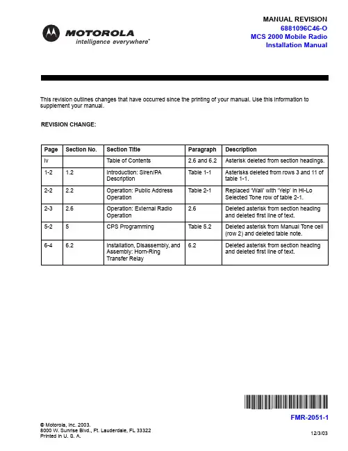
MANUAL REVISION12/3/03© Motorola, Inc. 2003.8000 W. Sunrise Blvd., Ft. Lauderdale, FL 33322Printed in U. S. A.This revision outlines changes that have occurred since the printing of your manual. Use this information to supplement your manual. REVISION CHANGE:Page Section No.Section Title Paragraph Descriptioniv Table of Contents2.6 and 6.2Asterisk deleted from section headings.1-2 1.2Introduction: Siren/PA DescriptionTable 1-1Asterisks deleted from rows 3 and 11 of table 1-1.2-22.2Operation: Public Address OperationTable 2-1Replaced ‘Wail’ with ‘Yelp’ in Hi-Lo Selected Tone row of table 2-1.2-3 2.6 Operation: Ex t ernal RadioOperation 2.6Deleted asterisk from section heading and deleted first line of text.5-25CPS ProgrammingTable 5.2Deleted asterisk from Manual Tone cell (row 2) and deleted table note.6-46.2Installation, Disassembly, and Assembly: Horn-Ring Transfer Relay6.2Deleted asterisk from section heading and deleted first line of text.6881096C46-OMCS 2000 Mobile RadioInstallation Manual*FMR-2051-1*FMR-2051-1This Page Intentionally Left BlankTable of Contents Foreword.................................................................................................... F-ii Product Safety and RF Exposure Compliance.......................................................................................F-ii Manual Revisions................................................................................................................................... F-ii Computer Software Copyrights.............................................................................................................. F-ii Document Copyrights............................................................................................................................. F-ii Disclaimer............................................................................................................................................... F-ii Trademarks............................................................................................................................................ F-iiList of Figures (v)List of Tables (vi)Chapter 1Introduction.........................................................................1-11.1Notations Used in This Manual......................................................................................................1-11.2Siren P/A Description.....................................................................................................................1-11.3Cabling Diagram............................................................................................................................1-4Chapter 2Operation.............................................................................2-12.1Siren/PA Operation........................................................................................................................2-12.1.1Control Unit.......................................................................................................................2-12.2Public Address Operation..............................................................................................................2-22.2.1Control Head/DEK-Plus....................................................................................................2-22.3Siren Tone Operation....................................................................................................................2-22.3.1Control Head/DEK-Plus....................................................................................................2-22.4External Radio Operation..............................................................................................................2-32.4.1Control Head/DEK-Plus....................................................................................................2-32.5Airhorn Operation..........................................................................................................................2-32.6Manual Operation..........................................................................................................................2-32.7Speaker Protection Alert................................................................................................................2-32.8Power-Up Feature.........................................................................................................................2-42.8.1Siren State........................................................................................................................2-42.8.2DEK-Plus..........................................................................................................................2-4Chapter 3Theory of Operation............................................................3-13.1Overview........................................................................................................................................3-13.2Microprocessor and Control Interface............................................................................................3-13.2.1Bus Interface.....................................................................................................................3-13.3Low-Level Audio............................................................................................................................3-23.4High-Level Audio...........................................................................................................................3-2iv Table of Contents3.5Power.............................................................................................................................................3-33.6Power Control and Speaker Short Detection.................................................................................3-3 Chapter 4Configuration/Programming of the Siren/PA...................4-1 Chapter 5CPS Programming..............................................................5-1 Chapter 6Installation, Disassembly, and Assembly.........................6-16.1Cables............................................................................................................................................6-26.2Horn-Ring Transfer Relay..............................................................................................................6-46.3Disassembly and Assembly...........................................................................................................6-46.3.1Disassembly......................................................................................................................6-46.3.2Assembly..........................................................................................................................6-56.4Pushbutton Removal and Replacement........................................................................................6-5 Chapter 7Maintenance and Troubleshooting....................................7-17.1Overview........................................................................................................................................7-17.2Maintenance..................................................................................................................................7-17.2.1Public Address Input Sensitivity Test................................................................................7-17.2.2Frequency Response Test................................................................................................7-17.2.3Siren Output Power Test...................................................................................................7-17.2.5Speaker Short Circuit Protection Test...............................................................................7-27.2.6Operating Mode Retention Test*......................................................................................7-27.2.7Version Display in Test Mode...........................................................................................7-2 Chapter 8Siren/PA Schematics and Mechanical Drawings.............8-1 Appendix A Replacement Parts Ordering..............................................A-1A.1Basic Ordering Information............................................................................................................A-1A.2Motorola Online..............................................................................................................................A-1A.3Mail Orders....................................................................................................................................A-1A.4Telephone Orders..........................................................................................................................A-2A.5Fax Orders.....................................................................................................................................A-2A.6Parts Identification.........................................................................................................................A-2A.7Product Customer Service.............................................................................................................A-2 Index..............................................................................................................I-iDecember 2, 20036881096C46-OChapter 1Introduction1.1Notations Used in This ManualThroughout the text in this publication, you will notice the use of note, caution, warning, and danger notations. These notations are used to emphasize that safety hazards exist, and due care must be taken and observed.NOTE:An operational procedure, practice, or condition that is essential to emphasize.1.2Siren P/A DescriptionThe MCS 2000 Siren/PA is an external accessory that generates siren tones and amplifies audiosignals from the radio for public address (PA). It can deliver 65, 75, or 100 watts of siren power to an11 ohm speaker, or 130 watts to dual 11 ohm speakers. In the PA mode, it can deliver 50 watts ofaudio power.This accessory consists of the Siren/PA unit and the cables that connect the Siren/PA to your MCS 2000 radio system.The Siren/PA unit is usually located in the cargo area of a vehicle. It can be operated using one of the following:•Mobile radio control head•Direct Entry Keyboard (DEK-Plus).1-2Introduction: Siren P/A Description Some Siren/PA features can be programmed by a qualified radio technician using the CustomerProgramming Software (CPS). A summary of available features for each Siren/PA configuration isshown in Table 1-1.Table 1-1. Siren/PA FeaturesFeature Using the Control Head Using the DEK-Plus Wail/Yelp/Hi-lo tones Yes Yes“Airhorn” tone Yes YesSiren manual tones No NoPublic address Yes YesExternal radio Yes YesPA volume control Yes YesSiren power control Automatic AutomaticSpeaker short protection Yes YesYes YesProgrammable parameters(using the radio codeplug)Power-up self check Yes YesHorn-Ring override No NoSiren State retained (while radio off)No*No** Not available in initial offering.December 2, 20036881096C46-OChapter 2Operation2.1Siren/PA Operation2.1.1Control UnitDepending on the installed configuration, the Siren/PA may be controlled by buttons on the control head or on the DEK-Plus.Figure 2-1: Model III Control Head with Siren/PA FunctionsFigure 2-2: Direct Entry Keyboard (DEK-Plus)2-2Operation: Public Address Operation2.2Public Address OperationThe Public Address feature amplifies and broadcasts the user's voice over the siren speaker.2.2.1Control Head/DEK-PlusTo activate the Public Address function, momentarily press the PA button. The corresponding light-emitting diode (LED) will light up and the PA feature will be activated.The control head display will temporarily show the current PA volume setting. To set the PA volume, rotate the radio's volume control (the rotary knob on the control head).NOTE:If you adjust the PA volume with the rotary knob on the control head, it will change the radio's volume setting based on the position of the knob.To use the Public Address feature, press the Push-To-Talk (PTT) button and speak into themicrophone. Your voice will be amplified and broadcast over the siren speaker.NOTE:The PTT button cannot be used to transmit while the PA feature is activated.If the Public Address and Siren options are both activated, the Siren function will be overridden when the PTT is pressed. The Public Address feature will have priority, and any siren tone or incomingradio signals (if in External Radio mode) will be abruptly muted.To turn off the Public Address, momentarily press the PA button again.2.3Siren Tone OperationWail, Yelp and Hi-Lo siren tones are broadcasted over the siren speaker. Use the Siren function to toggle between siren tones when broadcasting.2.3.1Control Head/DEK-PlusTo turn on the Siren function, press the Siren button momentarily. Then press the Wail, Yelp, or Hi-Lo buttons to broadcast the desired tone. The corresponding LEDs light up and the control headdisplay temporarily shows the selected siren tone.Any time the siren tone is changed, the display will briefly show the newly selected tone (even if the Siren function is off). To change the tone, press the Siren button on the DEK-Plus or Sirn button on the control head momentarily.If the Horn-Ring accessory is connected, you can change the siren tone by pressing the vehicle’sHorn-Ring while broadcasting a siren tone. (The operation of the Horn-Ring feature is shown inTable 2-1.)NOTE:You can change the siren tone at any time. The Siren function does not have to be activated.Table 2-1. Horn-Ring OperationSelectedChanges to NoteToneWail Yelp Press and release the Horn-Ring to change to Yelp tone. Press theHorn-Ring again to return to Wail tone.Yelp Airhorn Press the Horn-Ring to create the Airhorn tone. Airhorn sounds aslong as the Horn-Ring is pressed. Release the Horn-Ring to returnto Yelp tone.Hi-Lo Yelp Press and release the Horn-Ring to change to Yelp tone. Press theHorn-Ring again to return to Hi-Lo tone.December 2, 20036881096C46-OOperation: External Radio Operation2-32.4External Radio OperationThe External Radio feature amplifies and broadcasts incoming radio messages over the sirenspeaker, allowing radio communications to be heard outside the vehicle.2.4.1Control Head/DEK-PlusTo enable the External Radio feature, turn the Siren function on by momentarily pressing the Siren button on the DEK-Plus or the Sirn button on the control head. Then, select the External Radiofunction by pressing the Ex Rd button. The corresponding LEDs will illuminate.To adjust the External Radio volume, turn the volume control (rotary knob) on the control head.To turn off the External Radio feature, press the Siren button on the DEK-Plus or the Sirn button on the control head again, or select a different Siren function (Wail, Yelp, etc...). Once you turn off the External Radio function, the radio's receive volume will correspond with the position of the rotaryknob on the control head.2.5Airhorn OperationThe Airhorn feature—available with the Control Head and DEK-Plus configurations—broadcasts an airhorn tone over the Siren speaker. To broadcast the Airhorn, momentarily press the Ar Hn button.To turn off the Airhorn, press the Ar Hn button again.2.6Manual OperationThe Manual function—available with the Control Head and DEK-Plus configurations—allows theHorn-Ring to activate a siren tone.To enable the siren tone to be generated via the Horn-Ring, press the Man and Siren buttons. The corresponding LEDs will illuminate. Press the Horn-Ring to broadcast the pre-set tone (tones areprogrammed in the CPS, the default tone is “Wail”). You can program the Horn-Ring to generate the following tones:•Manual Wail: Pressing the Horn-Ring activates a rising Wail that peaks at 1500 Hz andcontinues as long as the Horn-Ring is held. When you release the Horn-Ring, the Wail tonefalls until the tone is muted.•Manual Yelp: Pressing the Horn-Ring activates a Yelp tone that continues as long as the Horn-Ring is held. When you release the Horn-Ring, the tone immediately mutes.•Manual Airhorn: Pressing the Horn-Ring activates an airhorn sound that continues as long asthe Horn-Ring is held. When you release the Horn-Ring, the tone immediately mutes.2.7Speaker Protection AlertWhen a short exists, the system performs a routine to “protect” itself from further harm. If a speaker short occurs, any audio broadcast (Siren functions, PA audio) is terminated. The Control Headdisplays SPKR SHORT. When the problem is corrected, the Siren/PA returns to its previous operation.6881096C46-O December 2, 20032-4Operation: Power-Up Feature 2.8Power-Up Feature2.8.1Siren StateThe Siren/PA Accessory powers up in one of two ways:•Warm Start (battery power was not removed)•Cold Start (battery power was removed).2.8.2DEK-PlusIn a Warm Start with a DEK-Plus, the Siren will power up with the PA Volume, the siren tone, and the Siren On/Off in their previously selected state at power-down, and with the PA off.NOTE:In a Warm Start with the DEK-Plus, the CPS may be used to program whether or not the Siren ON/OFF powers up in its previous state. This feature can be disabled, causing the Siren/PAto always power up with the Siren off.In a Cold Start, with a DEK-Plus, the Siren will power up with the default PA Volume, the Wail tone, the PA off, and the Siren off.December 2, 20036881096C46-OChapter 5CPS ProgrammingThe Customer Programming Software (CPS) stores programmed options in the radio’s codeplug.The CPS is preprogrammed with default settings at the factory, but it may be modified to suit yourneeds. There is one primary screen in the CPS for editing the Siren/PA options. To access thisscreen, double-click the “Radio Wide” tab shown in Figure 5-1.Figure 5-1: “Tree View” Screen ShotUnder the “Siren Operation” field, the “Siren/PA” option must be selected in order to modify the unit’s CPS options. Selecting the “PA Only” option will only allow you to modify the Public Address options.Figure 5-2: “Siren/PA Options” Screen Shot5-2CPS Programming: The Siren/PA Options screen enables you to modify various Siren/PA options (default settings areindicated). The following tables describe the programmable fields and their settings:Table 5-1. Public Address FieldsField OptionsOptions Audio Muting Disabled (default): Routes all audio to the Public Address speaker when inExternal Radio Mode.Enabled: Prevents deciphered SECURENET® audio and Mobile VoiceStorage message playback from being heard over the external speaker.PA Ignition Sense Disabled (default): Public Address operable with ignition switch on or off.Enabled: Public Address operable only with ignition switch on.Ext Radio Ignition Disabled (default): External Radio operable with ignition switch on or off.Enabled: External Radio operable only with ignition switch on.Default PA Volume Level This field is programmed to set the Public Address volume level for initialpower-up. If no volume level is manually selected by the operator, thevolume will default to the setting in this field.The range is from 0 to 15 (default 11).Siren P/A After Reset LAST STATE* (default): The siren will power up in the same state, on or off,as at power-down (Warm Start).Off: Siren will always be off at power-up.*Not available in initial offering. See Table1-1, “Siren/PA Features,” on page1-2.Table 5-2. Siren FieldsField OptionsHi-Lo Airhorn Tones Disabled: Hi-Lo and Airhorn tones cannot be produced.Enabled (default): Hi-Lo and/or Airhorn tones are allowed.Manual Tone This field selects the Manual Tone that will be heard when the Horn-Ring ispressed. The choices are Ar Hn, Wail, or Yelp (default is Wail).Siren Ignition Sense Disabled: Siren tones operable with the ignition switch on or off.Enabled (default): Siren tones operable with ignition switch on.December 2, 20036881096C46-OInstallation, Disassembly, and Assembly: Cables6-34.Route the red power cable to the vicinity of the battery positive terminal. Be careful to avoidareas where the cable might be subjected to abrasion or high temperatures, and use rubbergrommets wherever the cable passes through a bulkhead, such as the firewall.5.Locate the fuse holder as close to the battery as possible and away from any hot enginecomponents.a.Mount the fuse holder using the provided mounting hole and dress wires as necessary.b.Connect the fuse holder red adaptor lead plug to the mating receptacle on the red powercable of the Siren/PA unit (see Figure 6-3).6.Connect the power cable red lead from the fuse holder to the positive (+) battery terminal.7.Plug fuse into in-line fuse holder (see Figure 6-3).Figure 6-3: Power Cable Assembly8.Route the radio cable to the radio. Observe that the radio has two connectors on its frontpanel. The radio control head should be connected to the left connector, and the Siren/PAshould be connected to the right connector, facing the radio. (See Figure 6-2.)9.(a)Control unit cable—for units using a DEK-Plus:•In the Dash Mount Configuration, the HKN6137 (MCS 2000, 4 ft. DEK-Plus) cable isused.•In the Remote Mount Configuration, the HKN6136 (MCS 2000, 17 ft. DEK-Plus) cableis needed.(b)When the Siren/PA is controlled from the radio, no control unit connection is supplied. 6881096C46-O December 2, 20036-4Installation, Disassembly, and Assembly: Horn-Ring Transfer Relay6.2Horn-Ring Transfer RelayIn order to make Siren operation more convenient under emergency conditions, the vehicle’s Horn-Ring (or buttons) can be used to control siren functions (refer to Chapter 2 on page 2-2). Thisconvenience allows the driver to concentrate on the road and traffic conditions.Figure 6-4 shows wiring diagrams for connecting the Horn-Ring via a transfer relay for both negative and positive ground systems. As an alternative, a simple momentary contact pushbutton (normallyFigure 6-4: Siren/PA Horn-Ring Connections6.3Disassembly and AssemblyItem numbers in parentheses refer to parts identified in Figure8-6, on page8-9 in Chapter 8 of this manual.6.3.1Disassembly1.Place the Siren/PA on a workbench with the top cover (2) upward. Loosen four screws (1)and remove the top cover (2) from the chassis (8).2.Remove the component side shield cover (27) by prying the corners from the shield fence(28) and lifting upward.3.Remove the main PC board as follows:a.Remove the screw (29) near the connector (11).b.Remove the screw (12) and bracket (13) that attach the bus assembly (14).c.Remove two screws (15) from either side of the PC board (16).December 2, 20036881096C46-O。

Motorola CT220C 有线电话欢迎您...使用您新购买的摩托罗拉CT220C有线电话!产品特色:• 来电号码及来电时间记录50组(8位)或32组(16位),去电号码14组(8位)或8组(16位)及通话时间记录、翻查、删除、回拨功能• 16位LCD显示• LCD亮度5级可调• 1~99小时免打扰• 16首普通铃声选择• 4档振铃音量及2级免提音量• FLASH时间90/95/100/120/180/300/600/1000ms可选,默认600ms • 3组闹铃功能设置,每组闹铃声音不同• 音乐HOLD功能,并机提机自动解除• 在忘记收线或挂机不好时,自动收线• 8位计算器• 8位出局码• 8位本地码,来电自动过滤• 重拨、暂停、回拨功能• 静音功能• 使用指示灯• 挂机状态,32位预拨号及消号功能• 摘机背光功能• 雷电保护线路需要帮助吗?如果您在CT220C的设置或使用上有任何问题,请拨打4008-838-698 联系客服部门。
1您必须向您的网络提供商申请来电显示服务,方能实现上述功能的使用。
申请可能需要付费。
本说明书可提供您所需的一切信息,帮助您充分利用电话机的功能。
请依照接下来的“使用前的准备”中的简易指示设置好您的电话。
重要事项只可使用产品配备的电话线。
您的配备齐全吗?• 听筒和曲线• 座机• 电话线1.使用前的准备 (6)2.认识您的电话 (8)3.电话功能操作 (11)3.1座机操作说明 (11)3.1.1 拨打电话 (11)3.1.2 挂机预拨号 (11)3.1.3 挂断电话 (11)3.1.4 接听电话 (11)3.2音乐保持 (11)3.3重拨、暂停功能 (11)3.4音量调节 (12)3.5自动收线 (12)3.6关闭送话(静音功能) (12)3.7自动追拨 (12)4.话机设置 (13)4.1设置日期/时间 (13)4.2铃声选择及铃声音量调节 (13)4.3闹铃设置 (13)4.4免打扰时间设定 (14)4.5特殊功能选择设定 (14)4.6本地码与出局码设定 (14)4.7 LCD亮度调节 (14)4.8 IP功能设置 (14)45.回拨 (16)5.1回拨 (16)6.来电记录 (17)6.1来电查询 (17)6.2去电查询 (17)6.3删除功能 (17)7.贵宾存储 (18)8.计算器 (19)8.1 进入计算器模式 (19)9.帮助 (20)10.重要事项 (21)56使用前的准备1. 使用前的准备重要事项不要将CT220C 放置在浴室或其他潮湿的地区。
目录1 手持终端介绍1.1 motorola mc31902 手持终端日常操作2.1 充电方法2.2 开关机、热启动、冷启动3 手持终端无线网络配置3.1 无线网络配置4 手持终端联机pc机4.1 概述4.2 同步工具安装4.3 手持终端中文字库安装5 手持终端键盘功能设置 6手持终端机故障分析1 手持终端介绍1.1 motorola mc3190motorola 讯宝symbol mc3190数据采集终端作为symbol mc3090手持终端的升级替代产品,mc3190是构建于成功的mc3090之上,mc3190采集器系列分为3100批处理盘点机和包含无线局域网wifi的mc3190条码采集器两款。
新的摩托罗拉mc3190系列可为公司内部的按键应用提供成本高效的移动性和用户舒适度。
符合人体工程学的耐用型 mc3190 提供先进的计算能力以及数据采集能力、增强的安全性以及企业级的运动传感能力。
motorola 讯宝symbol mc3190数据采集终端性能参数:数据采集选项-1d 激光扫描仪、1d/2d 成像仪、dpm 内存 (flash/ram)-128mb ram/256 mb flash 或 128mb ram/512mb flash 处理器 (cpu)-marvell pxa320 @ 624 mhz 操作系统 (os)-microsoft windows mobile 6.1 classic, microsoft windows ce 6.0 pro 无线数据通讯:wpan(支持蓝牙技术)-ii 级、v2.1 增强数据速率 (edr), 集成天线wlan-三重模式 ieee? 802.11a/b/g;经过 ccxv4 认证;支持 ipv6;经过 fips140-2 认证(仅限mc3190)线性一维条码扫描器:光学分辨率-最小元素宽度 4 mil 扫描速率-104(+/- 12)次扫描/秒(双向)使用环境:环境密封-ip54(2 类)工作温度--4°至 122° f/-20°至 50° c 跌落规格-在工作温度范围内,多次从 4 英尺/1.2 米高处跌至水泥地面;满足并超过mil-std 810g 滚落规格-根据 iec 68-2-32,在室温条件下,500 次从 1.64 英尺/0.5 米高滚落(1,000次)2.1 充电方法摩托罗拉的每个手持终端都配了两粒电池,同时配了四位充电座。

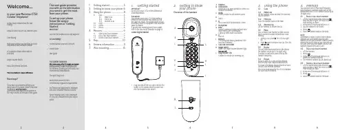
45678932 1. Getting startedIMPORTANTDo not place your CT50 in the bathroom orother humid areas.LocationY ou need to place your CT50 base within 2 metres of the telephone wall socket so that the cable will reach. The socket-outlet should be installed near the equipment and should be easily accessible.If you are wall mounting your phone please refer to the wall mount template on page 15.Connecting the handset1. Plug one end of the curly line cord into thesocket on the handset and the other end into the telephone wall socket.1. Getting started (5)2. Getting to know your phone 63. Using the phone (8)3.1Calls (8)3.1.1 Make a call 83.1.2 End a call83.1.3 Receive a call 83.2 Mute ................................................................83.3 Redial .............................................................83.4Recall (8)4. Memory (9)4.1 Store a two-touch number ..................94.2 Dial a two-touch number .....................94.3Delete a two-touch number (9)5. Help ..................................................106. General information ..................117.Wall mounting (15)This user guide provides you with all the information you need to get the most from your phone.T o set up your phone, follow the simpleinstructions in ‘Getting Started’.IMPORTANTOnly use the telephone line cord supplied.Got everything?• Corded handset and curly line cord • Corded base• User guideFor a better tomorrowresearch, engineering and supply chain management to make better products for everyone, focusing on both social and environmental responsibility.The right thing to do.• Meets and/or exceeds EMEAenvironmental regulatory requirements.• Eco friendly packaging with a minimum20% post consumer recycled content.• Phone housing is built with a minimumof 25% post consumer recycled content plastic.Welcome...to your new Motorola CT50 Corded Telephone!• 10 two-touch memory keys for easydialling.• Redial to easily dial the last number called.• T one dialling.• Mute your caller so you can have a privateconversation with someone nearby.• LED indicator shows when mute isactivated.• Ringer volume switch.• Recall for network functions.•Need help?If you have any problems setting up or using your CT50, please contact Customer Services on xxxxxxxxxxxxx .Alternatively, you may find the answer in the ‘Help’ section at the back of this guide.2. Getting to knowyour phoneOverview of the handsetAB CD E FGH IJA EarpieceB Hook switchHangs up a call when pressed or when you replace the handset.C RedialPress to redial the last number called.D *Dial a *.E RRecall used with switchboards / PABX.F MicrophoneG MuteSpeak to someone nearby without your caller hearing the conversation. Lights up when mute is activated.H #Dial a #.IMemoryFor storing and dialling numbers in the two-touch memory.J Curly line cord socketK Ringer switchSwitch the ringer volume between high, L Ring indicator LEDFlashes to indicate an incoming call.3. Using the phone3.1Calls3.1.1Make a callLift the handset, when you hear the dial tone, dial the number.3.1.2 End a call Place the handset back on the base.3.1.3Receive a callLift the handset to answer the call.3.2 MuteY ou can mute your handset so that you can talk to someone nearby without your caller hearing.1. During a call, press . The LED will lightup.2. Press again to resume your call. The LED3.3 RedialThe last entry dialled is stored in the phone; the number can be up to 32 digits long.T o redial the last entry called, pick up the handset and press r .3.4 RecallRecall is useful to access certain network services and PABX /switchboard services.For more information about network services contact your network operator.The recall mode preset in the CT50 is suitable for your country network.4. MemoryY ou can store one of your most frequently used telephone numbers under each of the number buttons 0-9, the number can be up to 32 digits long.4.1 1. mute button will flash.2. Press one of the keypad buttons 0-9.3. Dial the number to be stored.4.5. Place the handset back on the base.NOTERemember to make a note of which phone numbers are store under which keypadnumber on the label provided. You will need to remove the plastic plate so you can write on the card. Once you have made a note of the numbers replace the plastic plate.4.2 Dial a two-touch number1. Lift the handset.2.3. Press one of the keypad buttons 0-9,where the number is stored.4. The memory number will be dialled out.4.3 1. mute button will flash.2. Press one of the keypad buttons 0-9.3. 4. Place the handset back on the base.K L101112131415peripheral equipment are excluded from coverage.Unauthorized Service or Modification .Defects or damages resulting from service, testing, adjustment, installation, maintenance, alteration, or modification in any way by someone other than Motorola, SUNCORP or its authorized service centres, are excluded from coverage.Altered Products. Products or Accessories with (a) serial numbers or date tags that have been removed, altered or obliterated; (b) broken seals or that show evidence of tampering; (c) mismatched board serial numbers; or (d) nonconforming or non-Motorola branded housings, or parts, are excluded from coverage.Communication Services . Defects, damages, or the failure of Products or Accessories due to any communication service or signal you may subscribe to or use with the Products or Accessories is excluded from coverage.How to Obtain Warranty Service or Other Information?T o obtain service or information, please call: XXXXXXXXXXX.Y ou will receive instructions on how to ship the Products or Accessories at your expense and risk, to a SUNCORP Authorized Repair Centre. T o obtain service, you must include: (a) the Product or Accessory; (b) the original proof of purchase (receipt) which includes the date, place and seller of the Product; (c) if a warranty card was included in your box, a completed warranty card showing the serial number of the Product; (d) a written description of the problem; and, mostimportantly; (e) your address and telephone number.T echnical InformationHow many telephones can I have?All items of telephone equipment have a Ringer Equivalence Number (REN), which is used to calculate the number of items which may be connected to any one telephone line. Y our CT50 has a REN of 1. A total REN of 4 is allowed. If the total REN of 4 is exceeded, telephone types, there is no guarantee of ringing, even when the REN is less than 4.Connecting to a switchboardThis product is intended for use within Europe for connection to the public telephone network.7. Wall mountingIMPORTANTBefore you wall-mount your CT50, check that you are not drilling into any hidden wiring or pipes. Before you drill, make sure the telephone line cable will reach the socket.1. Drill two 4mm diameter holes in the wall10 or 7.2 cm apart vertically.MOTOROLA OR SUNCORP BE LIABLE, WHETHER IN CONTRACT OR TORT(INCLUDING NEGLIGENCE) FOR DAMAGES IN EXCESS OF THE PURCHASE PRICE OF THE PRODUCT OR ACCESSORY , OR FOR ANY INDIRECT, INCIDENTAL, SPECIAL OR CONSEQUENTIAL DAMAGES OF ANY KIND, OR LOSS OF INFORMATION OR OTHER FINANCIAL LOSS ARISING OUT OF OR IN CONNECTION WITH THE ABILITY OR INABILITY TO USE THE PRODUCTS ORACCESSORIES TO THE FULL EXTENT THESE DAMAGES MAY BE DISCLAIMED BY LAW.Some jurisdictions do not allow the limitation or exclusion of incidental or consequential damages, or limitation on the length of an implied warranty, so the above limitations or exclusions may not apply to you. This warranty gives you specific legal rights, and you may also have other rights that vary fromone jurisdiction to another. Normal Wear and T ear . Periodic maintenance, repair and replacement of parts due to normal wear and tear are excluded from coverage. Abuse & Misuse . Defects or damage that result from: (a) improper operation, storage, misuse or abuse, accident or neglect, such as physical damage (cracks, scratches, etc.) to the surface of the product resulting from misuse; (b) contact with liquid, water, rain, extreme humidity or heavy perspiration, sand, dirt or the like, extreme heat, or food; (c) use of the Products or Accessories for commercial purposes or subjecting the Product orAccessory to abnormal usage or conditions; or (d) other acts which are not the fault of Motorola or SUNCORP , are excluded from coverage.Use of Non-Motorola branded Products and Accessories. Defects or damage that result from the use of Non-Motorola branded or certified Products or Accessories or othercould be damaged by an electrical storm. We recommend that you unplug the telephone line cord during an electrical storm.Product disposal instructionsProduct disposal instructions for residential usersWhen you have no further use for it, please dispose the product according to your local authority’s recycling processes. For more information, please contact your local authority or the Retailer where the product was purchased.Product disposal instructions for business usersBusiness users should contact their suppliers and check the terms and conditions of the purchase contract and ensure that thisproduct is not mixed with other commercial waste for disposal.Consumer Products and Accessories WarrantyThank you for purchasing this Motorolabranded product manufactured under license by Suncorp T echnologies Limited, 2/F, Shui On Centre, 6-8 Harbour Road, Hong Kong. (“SUNCORP”)What Does this Warranty Cover?Subject to the exclusions contained below, SUNCORP warrants that this Motorola branded product (“Product”) or certified accessory (“Accessory”) sold for use with this product that it manufactured to be free from defects in materials and workmanship under normal consumer usage for the period outlined below. This Limited Warranty is your exclusive warranty and is not transferable.Who is covered?This warranty extends only to the firstconsumer purchaser, and is not transferable.What will SUNCORP do?SUNCORP or its authorized distributor at its option and within a commercially reasonable time, will at no charge repair or replace any Products or Accessories that do not conform to this limited warranty. We may use functionally equivalent reconditioned / refurbished / pre-owned or new Products, Accessories or parts.What Other Limitations Are There?ANY IMPLIED WARRANTIES, INCLUDING WITHOUT LIMITATION THE IMPLIEDWARRANTIES OF MERCHANTABILITY AND FITNESS FOR A PARTICULAR PURPOSE, SHALL BE LIMITED TO THE DURATION OF THIS LIMITED WARRANTY , OTHERWISE THE REPAIR OR REPLACEMENT PROVIDED UNDER THIS EXPRESS LIMITED WARRANTY IS THE EXCLUSIVE REMEDY OF THE CONSUMER, AND IS PROVIDED IN LIEU OF ALL OTHER WARRANTIES, EXPRESS OF IMPLIED. IN NO EVENT SHALL6. General informationIMPORTANTThis product is intended for connection to analogue public switched telephone networks and private switchboards in Europe.Important safety instructionsFollow these safety precautions when using your phone to reduce the risk of fire, electric shock, and injury to persons or property:• Do not set the phone on a heating registeror over a radiator. Ensure that proper ventilation is provided at the installation site.• Do not use while wet or while standing inwater.• Do not use this product near water (forexample, near a bath tub, kitchen sink, or swimming pool).• Do not disassemble this product. If serviceor repair work is required, contact the customer service helpline found in this User Guide.• Avoid using during an electrical storm.Use a surge protector to protect the equipment.Installation Guidelines• Read and understand all instructions andsave them for future reference.• Follow all warnings and instructionsmarked on the product.• Do not install this product near a bath tub,sink, or shower.• Do not place this product on an unstablecart, stand, or table. This product may fall, causing serious damage to the product.• Adjust only those controls that arecovered by the operating instructions. Improper adjustment of other controls may result in damage and will often require extensive work to restore the product to normal operation.Cleaning• Clean the handset and base with a damp(not wet) cloth, or an anti-static wipe.• Never use household polish as this willdamage the product. Never use a dry cloth as this may cause static shock.Environmental• Do not expose to direct sunlight.• Do not place your product on carpets orother surfaces which generate fibres, or place it in locations preventing the free flow of air over its surfaces.• Do not submerge any part of your productin water and do not use it in damp or humid conditions, such as bathrooms.• Do not expose your product to fire,explosives or other hazardous conditions.• There is a slight chance that your phone5. HelpNo dial tone• Use only the telephone line cord supplied.• Check that the telephone line cord isconnected properly.Storing numbers• Once you have stored a number there isno confirmation tone, just hang up the handset.• Remember to make a note of yourmemory numbers on the card provided.Cannot hear your caller• Make sure mute is not activated. If the LEDis lit pressManufactured, distributed or sold by licensee for this product. MOTOROLA and the Stylized M Logo aretrademarks or registered trademarks of Motorola Trademark Holdings, LLC.and are used under license. All other trademarks are the property of theirrespective owners. © 2017 Motorola Mobility LLC. All rights reserved.Version 7 (EU)Motorola CT50 Corded T elephoneCompact simplicityEU Declaration of ConformityWe, Meizhou Guowei Electronics Co., Ltd. declare under our sole responsibility that the following products:Brand name: Motorola Type: CT50 Descriptions: Corded telephone.to which this declaration related is in conformity with the essential requirements of the following directives of the Council of the European Communities:- Low Voltage Directive (2014/35/EU) - EMC Directive (2014/30/EU)The products are compliant with the following standards:Safety: EN60950-1: 2006+A11:2009+A1:2010+A12:2011+A2:2013 EMC: EN55032:2015 and EN55035:2017For and on behalf of Meizhou Guowei Electronics Co., Ltd.Signature: ______________________Printed name & Position:Raymond Leung –Chief Technical OfficerDate:18 December 2018Place:AD1 Section, Economic Development Area, Dongsheng Industrial District, Meizhou, Guangdong, China.。

MD481_MD491摩托罗拉无绳电话简易使用说明书【商品简介】银色外观,简洁时尚、典雅大方、充满活力子机两侧防滑条设计,手感舒适超大液晶屏5行字符清晰显示,带高亮度橙色背景灯光手机3X4按键橙色夜光,大按键,方便拨号待机时时间/日期显示2.4G数字高清晰传送,抗干扰性强,Hi-Fi音质圆润清晰最新数字通讯技术(SST跳频扩频),保密性更强频道自动搜索/呼叫/查找超静音,无电磁辐射,健康环保多信道,通话前和通话中自动扫描功能独占式通话保密功能,子机通话中主机无法听全部功能都可通过子机操作和DECT兼容、子母机双拨号系统主机可呼叫手机,更可实现主机和手机对讲主、子机之间内部呼叫、通话功能寻呼子机功能(子机放在什么地方找不到,这个功能最有用了)可增加子机,最多增加4个,子机间可内部通话支持3方电话会议来电12种个性和弦铃声选择电话簿贵宾来电专用铃声功能人性化设计,可分别设置白天和晚上的铃声响度,共4档调节,高、中、低、关闭振铃音量、音调控制增大/减小听筒音亮主机有免提通话功能,通话音量9档调节,手机也有免提通话功能,通话音量4档调节主机和手机都有来电显示系统(FSK制式)查阅已拨、未接、已接电话号码及快速拨号可存储50组来电号码,重复来电显示,新来电提醒来电回拨功能电话簿功能,子机可存储50组姓名和号码,主机49组30组来电号码储存,10组快速拨号底座内置MOTO Tapeless数字式答录系统,15分钟语音储存通话中可录音,录音时间长达15分钟可自录提示语,更可家庭内部留言无人自动应答留言系统,最多可留言99条3个数字语音信箱新留言提示功能异地遥控密码操控功能,在外面也可听取电话留言带耳机插孔,附送腰夹,方便交谈,解放你的双手可挂墙壁使用子机长达100小时的待机时间,连续4个小时的通话时间子机低电量自动警报保持/静音按键功能闪断/重拨按键功能日期/时间设置英语/法语/西语/葡语选择【商品附件】子机两个,主机一个,充电座一个,电源两个,电池两个,说明书一本【产品尺寸】座机:17.5 * 12 * 5 cm 子机:16.8 * 5.5 * 2.8 cm【使用说明】一、子机按键/开关/指示灯功能说明1. ON/flash 通话键/闪断键:按该键接听来点及拨打,在通话状态时如果你的电话开通了呼叫等待,按该键接听另一个来电。

纽曼C T V50使用手册Ver 8.14您好感谢您选用本公司生产的产品!本品为手持电视,可支持多种音频、视频、图片的浏览;还可随意的扩展空间,给您带来完美的便携影音播放世界。
播放设置更加人性化,足以体现您的个性风采,满足您的娱乐需求。
在使用本品之前,请仔细阅读我们随机提供的所有资料,本手册将为您介绍它的功能,使您在使用过程中更加轻松方便。
通过它您可以获取有关产品介绍、使用方法等方面的知识,以便您能更好地使用该产品。
在编写本手册时我们非常认真和严谨,希望能给您提供完备可靠的信息,然而难免有错误和疏漏之处,请您给予谅解并由衷地欢迎您批评和指正。
如果您在使用该产品的过程中发现什么问题,请及时拨打我们的服务热线,感谢您的支持与合作!请随时备份您的数据资料到您的计算机上。
本公司对于因软件、硬件的误操作、产品维修、电池更换或其它意外情况所引起的个人数据资料的丢失和损坏不负任何责任,也不对由此而造成的其它间接损失负责。
同时我们无法控制用户对本手册可能造成的误解,因此,本公司将不对在使用本手册过程中可能出现的意外损失负责,并不对因使用该产品而引起的第三方索赔负责。
本手册的信息以当前产品情况为准。
我们将继续开发提供新的功能,相关信息的更新恕不另行通知。
本手册信息受到版权保护,任何部分未经本公司事先书面许可,不准以任何方式影印和复制。
●产品及产品颜色款式请以购买的实物为准。
●本公司保留对本手册、服务手册及其相关资料的最终解释权。
企业执行标准:Q/BATB004-2010 企业标准备案:2010007使用注意事项★禁止儿童单独玩耍本机,请勿摔落或与硬物摩擦撞击,否则可能导致机器表面磨花、硬盘损伤、数据丢失或其它硬件损坏。
★建议不要大音量连续使用耳机,请将音量调整至合适的音量大小,并控制使用时间,以避免您的听力受损。
因为使用耳机时如果音量过大,可能导致永久性的听力损伤。
★请不要试图分解或改造本机,这样可能导致电击或妨碍产品质保。
SED 5310移动电话中文用户手册中国电子CECTV50移动电话中文用户手册二○○五年八月V50移动电话中文用户手册感谢您选购了CECT手机,为使您的手机使用在最佳状态,请详细阅读本手册手册阅读说明在手册中使用不同的排版样式说明不同的操作细节,具体说明如下:操作内容描述举例显示内容用正常字符表示0-9一般按键除功能键外所有的键,用正常字符加框表示0-9功能键功能键用加粗加框字体表示选择菜单项用黑体的斜体字表示保持通话注意:手册中使用的图片仅作为功能示意用图,可能与您的手机显示有所不同,请以您的手机为准。
IV50 移动电话中文用户手册I安全事项请仔细阅读这些简明的规则,以免产生危险或触犯法律。
电池:不要将电池短路。
如果金属物体与电池暴露在外的电极接触,就可能发生短路,造成财产损失、人身伤害或烧伤。
为防止意外漏电,应妥善放置已充电的电池,特别应注意放在您衣袋、钱夹或其他装有金属物的包中的电池。
注意行车安全驾车时请不要使用移动电话。
如要使用,请先停好车。
在飞机上应关机移动电话可造成干扰,在飞机上使用是非法的,登机前请关掉您的移动电话。
(手机的关机闹钟功能应处于关闭状态)在爆炸地点附近应关机为避免干扰爆破操作,在“爆破现场”或张贴“关掉双向无线电”图标的地方应关闭移动电话。
注意有关限制,并遵守任何有关的规定或条例。
在危险品附近要关机在加油站及靠近燃料和化学制剂等危险物品的地方,请关闭移动电话。
在医院里应关机在标明不可使用移动电话的医疗设备附近,请关闭移动电话。
移动电话会干扰植入的心脏起搏器、助听器以及其他医学植入设备。
贴近心脏起搏器使用移动电话会使设备功能紊乱。
应避免将话机放在心脏起搏器上,即上衣袋内。
干扰所有的移动电话都可能会受到干扰,从而影响电话的性能。
配件和电池只能使用厂家指定的配件和电池。
电池更换不当会造成危险。
本机由CECT 指定的旅行充电器,台式充电座充电,使用其他充电设备将可能导致危险。
3BusinessPhone 250 - Executive T elephoneBusinessPhone 50 - Executive T elephone Welcome to the User´s Guide for the Executive phone in the BusinessPhone 250 / BusinessPhone 50 system from Ericsson.It is a state-of-the-art business communications system. Its alliance of features and facilities effective-ly improves communications for virtually any kind of organization. T o take full advantage of these advanced features and facilities there is a line of phones, designed for ease of use in every situation.Y our phone is equipped with programmable keys for single-key access to frequently used functions and numbers. Step-by-step instructions in the display assist your actions on the phone. Only a selec-ted number of display images, however, are shown in the User´s Guide for your reference.Note:The features described in this user´s guide are related to version 4.0 of the BusinessPhone 250 /BusinessPhone 50 system, some features described in this guide might not work in earlier version of the system.Some features described in this user´s guide might be protected by a hardware dongle that has to be bought separately.The User´s Guide describes the facilities of the BusinessPhone system and the Executive phone with a factory defaults programming. There may be some differences in the way your phone is program-med. Please consult your system administrator if you need further information.Function descriptions that do not include speaking in the handset, are described as off-hook, if nothing else is stated. Instead of pressing the ”Clear-key”, you can always replace the handset.The dual-functions keys allow two functions to be combined on the same keys, the primary shown above and the secondary shown below the line. T o access the secondary function, you just press the key 2nd and then the function key.Note:Dialog 3213 is a system telephone, i.e. it can only be used for an Ericsson private branch exchange that supports this type of telephone.Example:T o access the Information function:Press the key 2ndthen press the combined keyMessage/InfoDialog 3213BusinessPhone 250 / BusinessPhone 50Table of ContentspageDescription (5)Incoming calls (8)Outgoing calls (10)During calls (13)Call forwarding (18)Information (23)Internal messages (28)Mailbox system (32)Abbreviated numbers (36)Call metering (40)Group facilities (49)Other useful facilities (53)Security (59)Least Cost Routing (61)ISDN facilities (62)Optional equipment (68)Programming (71)Display info (75)Visible signals (77)Audible adjustments (78)T ones and signals (80)Write text (81)Glossary (82)Installation (84)Useful hints (87)Index (88)Quick reference guide (91)4BusinessPhone 250 - Executive T elephoneBusinessPhone 50 - Executive T elephone5BusinessPhone 250 - Executive T elephoneBusinessPhone 50 - Executive T elephoneDESCRIPTION(continued)5Dual-function programmable keys (A-N)Storing numbers, program functions. See section ”Programming”.6Dual-function programmable key (C) / Headset keya. Storing numbers and program functions.b. The headset function is only available with option unit(DBY 410 02) installed. The headset key is programmed bythe system administrator. See section ”Optional equipment”.7Transfer / Diversiona. T ransfer an ongoing call. See section ”During calls”.b. Activate/Deactivate diversion. See section ”Call forwarding”.8Inquiry / Conferencea. T o make an inquiry to an internal or external party.b. T o establish a telephone conference.See section ”During calls”.9Line 2 / Read &a. Line key 2 for in and outgoing calls.b. Read information. See section ”Information”.10Line 1 / Save/Rediala. Line key 1 for in and outgoing calls.b. Save or redial an external number. See section ”Outgoing calls”.11Volume controlTo adjust the volume. Also space/backspace in writing mode.See sections ”Audible Adjustments” and ”Write text”.12MuteT o switch the microphone on or off. See section ”During calls”.13Loudspeaker on/offT o switch the loudspeaker on or off. See section ”During calls”.14ClearTo disconnect calls or to clear the display in programming.15Microphone6BusinessPhone 250 - Executive T elephoneBusinessPhone 50 - Executive T elephone7BusinessPhone 250 - Executive T elephoneBusinessPhone 50 - Executive T elephone 16Optional key panel (A-Q)17 dual-function programmable keys per key panel.Four panels can be connected.Note:If one or two key panels are used, the optional key panel DBY 409 01 may be used. However, if three or four key panels are used, all optional key panels must be of type DBY 409 02.17Loudspeaker 18Handset with hearing aid functionPlease note:The handset may retain small metal objects in theearcap region.8BusinessPhone 250 - Executive T elephoneBusinessPhone 50 - Executive T elephone9BusinessPhone 250 - Executive T elephoneBusinessPhone 50 - Executive T elephone10BusinessPhone 250 - Executive T elephoneBusinessPhone 50 - Executive T elephoneBUSY EXTENSION You call an extension and receive busy tone.Camp-on You can notify a busy extension of your call by a mutedringing call (if this function is allowed).camp-on Press (see display)Keep the handset off hook. When the called extensionreplaces the handset, it will be called automatically.Note: If you receive the busy tone again, the desired extensiondoes not allow camp-on.Intrusion You can intrude on an ongoing call on a busy extension(if this function is allowed).intrusion Press (see display)Intrusion tone is heard and a three-party call is established.When the called extension replaces the handset and youkeep off hook, the called extension will be recalledautomatically.Note: If you still hear the busy tone, then your extension does nothave the authority to intrude or the desired extension is protectedagainst intrusion.PRINTOUT The printout covers the following information: Example:Call Metering Information BusinessPhoneDate: 99 05 12Time: 10:53ERICSSON AUSTRIA AGPottendorfer Str. 25-271121 ViennaAUSTRIAReason for print out : ReadDivision : Total systemGroup : CallersDirectory number range : 4736Currency : ATSDir. Pulses Cost Cost/Pulse4736Mr.Plattner76760.0010.00Total76760.00PRINTOUT CONTENTSDate:Shows the date of the print out.Time:Shows the time of the print out.Ericsson Austria AG 4 lines with 50 characters per line are free for definition. Pottendorfer Str. 25-27For example, for the company address.1121 ViennaAUSTRIAReason for print out:This field shows if the print out was initiated only to readout the counter or if the print out was caused because of areset procedure.Division:This field is prepared for future applications. Currently italways shows ”T otal system”.Group:Shows if the desired directory number(s) are related to theextension (caller) or trunk group.Directory number Shows the directory number of the desired extension or range:trunkline. When no directory number is entered then ”ALL”will be shown in this field and you will see all the counters ofthe extensions and trunk lines on the display. Currency:Shows the defined currency.Dir.No.:Shows the directory number of the desiredextension/trunk line.Name:Shows the name of the extension or trunk line.Pulses:Shows the accumulated pulses for the desiredextension/trunk line since the last reset.Cost:Shows the accumulated cost for the desiredextension/trunk line since the last reset.Cost/Pulse:Shows the actual price per pulse.T otal:Shows the accumulated pulses and costs of all theextensions/trunk lines on the printout.。
178/03Radio Service Software Part No. Radio Cross-ReferenceRVN4106B 3.5“-10” PROD CONFIG TOOL RVN4126E 3.59100-386-9100-386/T DEVICE RVN4177M 2-CD 2-3.5MCS/MTSRVN4182F 1-CD 2-3.5XTS3000/SABER (PORT)YES RKN4046AHVN9085B 3.51-20 RNO HLN9359 PROG. STAND RVN4057C 3.532 X 8 CODEPLUGNO 3080385B23 & 5880385B30MDVN4965C 3.59100-WS/T CONFIG KIT RVN4085C 3.5ADVAN. SECUREMENT CIU NO 0180358A25RVN4053Q 3.5ASTRO DIGITAL INTERFACE NO 3080385B23RVN4184F 2-CD RKN4046A (Portable)2-3.5ASTRO PORTABLE /MOBILE YES 3080369B73 or 0180300B10(Mobile)RVN4183F 1-CD 3080369B732-3.5ASTRO SPECTRA (MOBILE)YES (Low / Mid Power)0180300B10(High Power)RVN4185G CD ASTRO SPECTRA PLUS MOBILE NOMANY OPTIONS; SEE SERVICE BRIEF #SB-MO-0101RVN4186G CD ASTRO SPECTRA PLUS MANY OPTIONS;MOBILE/PORTABLE COMB SEE SERVICE BRIEF #SB-MO-0101RVN4154J 3.5ASTROTAC 3000 COMPAR.3080385B23RVN5003D 3.5ASTROTAC COMPARATORS NO 3080399E31 Adpt. 5880385B34RVN4083A 3.5BSC II NO FKN5836ARVN4171B 3.5C200RVN4029K 3.5CENTRACOM SERIES II NO VARIOUS-SEE MANUAL 6881121E49RVN4112E 3.5COMMAND PLUS NO RVN4149D 3.5COMTEGRAYES 3082056X02HVN6053D CD CT250, 450, 450LSYES AAPMKN4004RVN4079G 3.5DESKTRAC CONVENTIONAL YES 3080070N01RVN4093F 3.5DESKTRAC TRUNKED YES 3080070N01RVN4091C 3.5DGT 9000 DESKSET YES 0180358A22RVN4107B 3.5FORMSGEN 9100-11RVN4114A 3.5GLOBAL POSITIONING SYS.NO RKN4021A HVN8177F 3.5GM/GR300/GR500/GR400 M10/12/130YES 3080070N01RVN4159A 3.5GP 60 SERIES YESPMLN4074AHVN9128D 3.5GP300 & GP350RVN4152C 3.5GP350 AVS RVN4150H 3.5GTXYES HKN9857 (Portable)3080070N01(Mobile)HVN9025L CD HT CDM/MTX/ER SERIES YES AARKN4083/AARKN4081 Ribless AARKN4075Ribless non-USA,RKN4074RVN4047A 3.5HT 10YES RTK4208B RVN4021C 3.5HT 50YES RTK4208B RVN4005H 3.5HT 600YES RTK4205C RVN4031C 3.5HT 800YES RTK4205C RVN4098H 3.5HT/JT1000-VISARYES3080371E46 (VISAR CONV’L)RVN4151B 3.5HT1000 AVSRVN4098H 3.5HT1000/ VISAR CONV’L.YES RKN4035B (HT1000)HVN9084B 3.5i750YES HLN-9102A RVN4130D 3.5INFOTAC MESSNG’R EDITOR RVN4156N 3.5LCS/LTS 2000YESHKN9857(Portable)3080070N01(Mobile)RVN4087A 3.5LORAN C LOC. RECV’R.NO RKN4021ARVN4135A 3.5M100/M200,M110,M400,R100 includes HVN9173,9177,9646,9774YES 3080070N01RVN4023G 3.5MARATRAC YES 3080070N01RVN4019K 3.5MAXTRAC CONVENTIONAL YES 3080070N01RVN4139C 3.5MAXTRAC LS YES 3080070N01RVN4043S 3.5MAXTRAC TRK””D.DUPLEX YES 3080070N01RVN4178ACDMC SERIES, MC2000/2500DDN6124AW/DB25 CONNECTOR DDN6367AW/DB9 CONNECTOR RVN4027B 3.5MCR 1000180358A52RVN4175M 1-CD Rib to MIC connector 1-3.5MCS 2000 RKN4062B RVN41131-3.5MCS2000RVN4011B 3.5MCX 1000YES 3000056M01RVN4063A 3.5MCX 1000 MARINE YES 3000056M01RVN4117C 3.5MDC/RDLAP DEVICES FVN4312A 3.5MICOM 2NOFLN2423RVN4105A 3.5MOBILE PROG. TOOL RVN4119C 3.5MOBITEX DEVICESRVN4059C 3.5MOSTAR/TRAXAR TRK’D.NO 3080367B90/ DUPLEX ADAPTER 0180359A29RVN4128A 3.5MPT1327-1200 SERIES YES SEE MANUAL RVN4025A3.5MSF 5000/PURC/ANALOGYES 0180355A30RVN4077G 3.5MSF5000/10000FLD YES 0180355A30RVN4017K 3.5MT 1000YES RTK4205C RVN4148N 3.5MTR 2000YES 3082056X02RVN4140C 3.5MTRI 2000NO RVN4176M 1-CD MTS2000, MT2000*, MTX8000, MTX90001-3.5*programmed by DOS which is included in the RVN4176RVN4131C 3.5MTVA CODE PLUG FIX RVN4131C 3.5MTVA CODE PLUG FIX RVN4142A 3.5MTVA DOCTOR YES 3080070N01RVN4131C 3.5MTVA3.EXE RVN4013K 3.5MTX 800 & 800S YES RTK4205C RVN4065H 3.5MTX 810YES RTK4205C RVN4033J 3.5MTX 900YES RTK4205C RVN4055H 3.5MTX 900S YES RTK4205C RVN4097 1-CDMTX8000/9000, MTS2000,MT2000*, MTX8000,programmed by DOS which is included in the RVN4176RVN4081F 3.5MTX820/820S/888/888S YES RTK4205C HVN9067E CD MTX850/8250MTX950,9250RVN4138B 3.5MTX-LS YES RKN4035D RVN4035B 3.5MX 1000YES RTK4203C RVN4073B 3.5MX 800YES RKN4006BHVN9395 P100, P200 LB, P50+, P210, P500, PR3000 “RVN4134B3.5P100 (HVN9175)P200 LB (HVN9794)P50+ (HVN9395)P210 (HVN9763)P500 (HVN9941)PR3000 (HVN9586)YES RTK4205HVN9852J 3.5P110YES HKN9755A/REX1143HVN9262E 3.5P200 UHF/VHF YES RTK4205HVN9941B 3.5P500YES 0180358A62RVN4129A 3.5PDT220YVN4051C 3.5PORTABLE REPEATER Portable rptr. P1820/P1821AX RVN4061C 3.5PP 1000/500NO 3080385B23 & 5880385B30RVN5002AF 3.5QUANTAR/QUANTRO NO 3O80369E31RVN4135A 3.5R100 (HVN9177)M100/M200,M110,M400YES 0180358A52RVN4146C 3.5RPM500/660RVN4002K 3.5SABER YES RTK4203C RVN4131C 3.5SETTLET.EXE HVN9007E 3.5SM50 & SM120YES RVN4039B 3.5SMART STATUS YES FKN5825A HVN9054D 3.5SOFTWARE R03.2 P1225YES 3080070N01HVN9001D 3.5SOFTWARE R05.00.00 1225LS YES HLN9359A HVN9012D 3.5SP50RVN4001N 3.5SPECTRA YES 3080369B73 (STANDARD) 0180300B10(HIGH POWER)RVN4099B 3.5SPECTRA RAILROAD YES 3080369B73RVN4110A 3.5STATION ACCESS MODULE NO 3.08E+37RVN4049E 3.5STX YES 0180357A54RVN4089A 3.5STX TRANSIT YES 0180357A54RVN4007E 3.5SYNTOR X 9000YES 0180353A75RVN4102B 3.5SYNTOR X 9000 DUAL YES 0180353A75RVN4069A 3.5SYNTOR X TRK’D.YES 0180353A75RVN4009F 3.5SYSTEM 9000E YES 0180353A75RVN4051F 3.5SYSTEMS SABER YES RTK4203B RVN4075D 3.5T5600/T5620 SERIES NO 3080385B23HVN9060D CD TC3000, TS3000, TR3000RVN4123G 3.5VISAR PRIVACY PLUS YES 3.08E+52FVN4333A 3.5VRM 100 TOOLBOX FKN4486A CABLE & ADAPTOR RVN4133K 3.5VRM 500/600/650/850NO RVN4181G CD XTS 2500/5000 PORTABLES RKN4105A/RKN4106A RVN41002- 3.5XTS3000 ASTRO PORTABLE/MOBILE RVN4170D3.5XTS3500YES RKN4035DRIB SET UPRLN4008ERADIO INTERFACE BOX (RIB)0180357A57RIB AC POWER PACK 120V 0180358A56RIB AC POWER PACK 220V3080369B71IBM TO RIB CABLE (25 PIN) (USE WITH XT & PS2)3080369B72IBM TO RIB CABLE (9 PIN)RLN4438A 25 PIN (F) TO 9 PIN (M) ADAPTOR (USE W/3080369B72 FOR AT APPLICATION)5880385B308 PIN MODULAR TO 25 PIN “”D”” ADAPTOR (FOR T5600 ONLY)”0180359A29DUPLEX ADAPTOR (MOSTAR/TRAXAR TRNK’D ONLY)8/03Radio ServiceSoftwarePart No. RadioCross-ReferenceU tilizing your personal computer, Radio Service Software (RSS)/Customer Programming Software (CPS) enables you to add or reprogram features/parameters as your requirements change. RSS/CPS is compatiblewith IBM XT, AT, PS/2 models 30, 50, 60 and 80. Requires 640K RAM. DOS3.1 or later. Consult the RSS users guide for the computer configuration andDOS requirements. (For HT1000, MT/MTS2000, MTX838/8000/9000, Visarand some newer products– IBM model 386, 4 MEG RAM and DOS 5.0 orhigher are recomended.) A Radio Interface Box (RIB) may be required as wellas the appropriate cables. The RIB and cables must be ordered separately.Licensing:A license is required before a software (RVN) order is placed.The software license is site specific (customer number and ultimatedestination tag). All sites/locations must purchase their own software. Besure to place subsequent orders using the original customer number andship-to-tag or other licensed sites; ordering software without a licensedcustomer number and ultimate tag may result in unnecessary delays. Toobtain a no charge license agreement kit, order RPX4719. To place an orderin the U.S. call 1-800-422-4210. Outside the U.S., FAX 847-576-3023.Subscription Program:The purchase of Radio Service Software/CustomerProgramming Software (RVN & HVN kits) entitles the buyer/subscriber tothree years of free upgrades. At the end of these three years, the subscribermust purchase the same Radio Service Software kit to receive an additionalthree years of free upgrades. If the subscriber does not elect to purchase thesame Radio Service Software kit, no upgrades will be sent. Annually asubscription status report is mailed to inform subscribers of the RSS/CPSitems on our database and their expiration dates.Notes:1)A subscription service is offered on “RVN”-Radio ServiceSoftware/Customer Programming Software kits only.2)“RVN” software must only be procured through Customer Care andServices Division (CCSD). Software not procured through the CCSD willnot be recorded on the subscription database; upgrades will not bemailed.3)Upgrades are mailed to the original buyer (customer number & ultimatetag).4)SP software is available through the radio product groups.2.58E+92 AC POWER PACK 220V3080390B49SMARTRIB CABLE (9 PIN (F) TO 9 PIN (M) (USE WITH AT) 3080390B48SMARTRIB CABLE (25 PIN (F) TO 9 PIN (M) (USE WITH XT) RLN4488A SMART RIB BATTERY PACKWIRELESS DATA GROUP PRODUTS SOFTWARERVN4106 3.5”-10” PROD. CONFIG”RVN4126 3.59100-386/9100T DEVICESMDVN4965 3.59100-WS/T CONFIG’TNRVN4107 3.5FORMSGEN 9100-11RVN4117 3.5MDC/RDLAP DEVICESRVN4105 3.5MOBILE PROG. TOOLRVN4119 3.5MOBITEX DEVICESRVN4129 3.5PDT220PAGING PRODUCTS MANUALS6881011B54 3.5ADVISOR6881029B90 3.5ADVISOR ELITE6881023B20 3.5ADVISOR GOLD6881024B15 3.5ADVISOR GOLD FLX6881020B35 3.5ADVISOR PRO6881020B35 3.5ADVISOR PRO FLX6881032B30 3.5BR850NLN3163C 3.5BRAVO PROG-KIT6881010B35 3.5BRAVO ALPHA6881012B37 3.5BRAVO CLASSIC6881015B76 3.5BRAVO ENCORE6881012B91 3.5BRAVO EXPRESS6881025B65 3.5BRAVO LX6881021B65 3.5BRAVO FLX6881012B37 3.5BRAVO PLUS6881031B70 3.5CP12506881029B20 3.5DIGITZ6881028B60 3.5EXPRESS XTRA / FLX6881028B60 3.5EXPRESS LUNA.6881016B06 3.5FREE SPIRIT6881028B10 3.5JAZZ6881032B30 3.5LS3506881032B30 3.5LS5506881032B30 3.5LS7506881033B10 3.5LS950V.6881012B37 3.5LIFESTYLE PLUS6881020B65 3.5MEMO EXPRESS6881035B20 3.5MINITOR III6881031B80 3.5PF1500-R506881031B85 3.5PF1500-R256880496G02 3.5PAGEFINDER8262947A15 3.5PAGEWRITER 20008262947A15 3.5PAGEWRITER 2000X6881021B65 3.5PRO ENCORE6881026B55 3.5PRONTO.6881023B55 3.5RENEGADE6880496G11 3.5TENOR6881028B10 3.5TALKABOUT T3406881029B35 3.5TIMEPORT P7308262947A15 3.5TIMEPORT P9306881023B65 3.5ULTRA EXPRESS6881025B75 3.5ULTRA EXPRESS FLX6881023B20 3.5V700 POCSAG6881029B90 3.5V700 FLEX6881029B25 3.5WORDLINE.6881029B05 3.5WORDLINE FLEXNLN3548B UNIVERSAL INTERFACE KIT18。