
AWG和公制(英寸和毫米)之间的换算关系
- 格式:pdf
- 大小:96.37 KB
- 文档页数:1
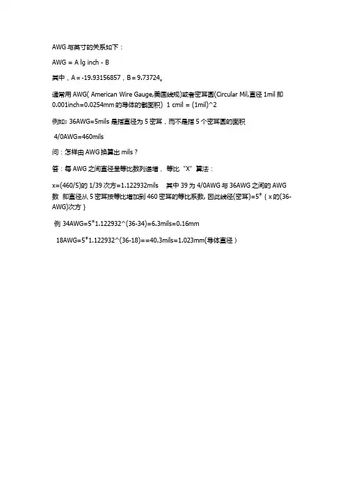

Table 8 Maximum Cable Length (m) for Gauge of Wire and Speaker Impedance在以太网和xDSL接入网设计中,经常会碰到诸如24AWG、26AWG等等表示电缆直径的方法。
其实AWG(American Wire Gauge)是美制电线标准的简称,AWG值是导线厚度(以英寸计)的函数。
下表是AWG 与公制、英制单位的对照表。
其中,4/0表示0000,3/0表示000,2/0表示00,1/0表示0。
例如,常用的电话线直径为26AWG,约为0.4mm。
由表中归纳出的AWG与英寸的关系如下: AWG = A lg inch - B其中,A=-19.93156857,B=9.73724。
以下摘自<BASSBOX XOVER>的ONLINE HELP.The purpose of the crossover network is to divide the sound between the drivers in a multi-driver speaker. How well this is accomplished is not just a matter of good design. It also requires good execution. This topic contains advice to help with execution.GeneralLet抯begin with some general suggestions:Measure all componentsIt is best to measure the value of all components before using them in a crossover network. This is best accomplished with an impedance bridge and tone generator. Ideally, the components should bemeasured at the crossover frequency.Lower-order networks like 1st and 2nd-order networks can usually tolerate greater component variations than higher-order networks like 3rd and 4th-order networks. If you are unsure whether a component value is close enough to work, try substituting the measured value in your X昽ver Pro design and plot the results. Use the graphs to evaluate the changes.Series components are the most criticalThe series components are the most important elements in a crossover network because the audio signal must pass through them before arriving at the driver. The parallel components serve as shunts to drain a portion of the audio signal away from the driver. There are ten series components in the three-way crossover network below (they are highlighted in pink).If you need to economize, it is best to do so with the parallel components and reserve the highest quality parts for the series components.ConnectionsTo make a good electrical connection between two or more components, begin by creating a strong mechanical connection. This can be as simple as carefully twisting their wire leads together. Take care not to put too much tension on each lead where it enters the component. A component with a broken lead is useless. Finally, solder the connections to create a long lasting, airtight connection. The wires should be heated enough to allow the solder to flow onto them but not so hot that a component is damaged.MountingUnless you have the resources to design and manufacture a printed circuit board (PCB) for the crossover network you will need to obtain some sort of flat and thin nonconductive material to serve as a circuit board for component mounting. Commonly used materials include hardboard and pegboard.Create a cut pattern for the circuit board by laying all the components on a piece of paper in their mounting position and drawing a rectangle around them. Use the pattern to cut the correct size piece from the circuit board material.When mounting the parts, it is important to not allow them to touch each other (except at the connections). This is especially true of inductors and resistors.The parts should be securely mounted to the circuit board so that they cannot vibrate. This can be accomplished by gluing them to the circuit board with a nonconductive adhesive. Commonly used adhesives include silicone rubber and epoxy glue.Most crossover networks are installed inside the speaker box. If this is done, it is important to keep the crossover network as far as possible away from the drivers. This is because the magnetic field of the drivers can interact with the crossover network and cause distortion. This problem is minimized when shielded drivers are used.Some designers recommend using brass screws to mount the circuit board. Unlike steel screws, brass screws will not interact with the magnetic fields of the crossover network components.CapacitorsGenerally speaking there are two kinds of capacitors used in crossover network construction: electrolytic and solid dielectric. Electrolytic capacitors must be the nonpolarized variety because audio signals have alternating current. Electrolytics are the most common and the cheapest capacitors. Unfortunately they are considered the least favorable because they tend to have more resistance (ESR) and inductance (both undesirable qualities in capacitors) and because they do not age well. Electrolytic capacitors usually have greater manufacturing variations, resulting in higher tolerance values. And their resistive and inductive attributes are usually worse at higher frequencies.Solid dielectric capacitors are usually considered much better choices because they have less resistance and inductance and are more stable as they age. However, they are also more expensive and are not usually available in the larger values. Examples of solid dielectric capacitors include polypropylene, polyester and Mylar.When large capacitance values are needed, high-voltage oil-filled (motor-run) capacitors are sometimes used.Use high quality capacitors in critical areasThe most important capacitors in a crossover network are the ones that are wired in series with the drivers. Whenever possible use higher quality capacitors for these locations. It is also a good idea to avoid the use of electrolytic capacitors for high-pass filters because they do not pass high frequency signals as well as solid dielectric capacitors. However there are solutions for this problem discussed below.The most forgiving location for cheap capacitors is in the low-pass filter where they are used at lower frequencies and are wired in parallel with the driver to serve as shunts.Improving capacitor performanceSome of the resistance and inductance problems of cheaper capacitors can be overcome with the addition of a high-quality bypass capacitor. These are usually small 0.1 to 2.0 礔Mylar capacitors that are paralleled with the cheaper capacitor. This can improve the high-frequency transient response considerably. Because the bypass capacitor is small it does not add much to the cost.Another way to improve the sound quality of cheaper capacitors is to parallel several smaller ones in place of a single larger one. For example, use three parallel 50 礔capacitors in place of a single 150 礔capacitor. By paralleling them, the capacitance adds, but the bad resistive and inductive qualities becomes smaller. The corollary to this is to avoid wiring two or more cheaper capacitors in series with each other because this increases their undesirable qualities.InductorsGenerally speaking there are two kinds of inductors used in crossover network construction: inductors with an air core and inductors with a metal core. Air core inductors are usually considered the best because they do not become saturated as quickly at higher power levels as comparable metal core inductors. This results in lower distortion and greater power handling for air core inductors. And, with a little patience, they can be made at home.Metal core inductors offer the advantage of higher inductance with lower resistance (DCR) compared to comparable air core inductors. This is because the metal core increases the amount of inductance per turn of wire, causing them to need fewer turns for a given inductance value. This also makes them smaller than air core inductors梐nother advantage.MountingInductors generate their own magnetic fields and they are susceptible to the effects of external magnetic fields. To minimize magnetic coupling between inductors, it is generally recommended that they be mounted at 90?angles to each other and that they be at least 3 inches (76 mm) apart. This is shown below:To minimize interference from external magnetic fields, they should not be located close to drivers, whose magnets can generate strong external magnetic fields (unless they are shielded).Keep resistance lowThe number one problem of inductors is excessive resistance. As a general rule, their DC resistance (DCR) should be no higher than 5% (1/20th) of the driver impedance (Z). This means that an inductor that is connected to an 8 ohm driver should have a DCR no higher than 0.4 ohms.To keep the DCR low, you can use a metal core inductor. However, if you can tolerate the larger size, a better solution might be to use an air core inductor that is made with a larger gauge of wire. The heavier the wire, the better. 16 gauge is a good starting point for low-pass inductors and 18 gauge is a good starting point for midrange drivers and tweeters.Note: The smaller the gauge number, the larger the wire and the smaller the resistance.Homemade inductorsIf you wind your own air core inductors, it is important to wind them tightly and to secure the windings so they cannot vibrate. Some claim that vibrating windings will create audible distortion. The windings can be secured with nylon wire ties or they can be dipped in either potting compound or a wire varnish.To reduce DCR when making your own inductor, use more than one strand of wire and parallel the ends. This has the same effect as using a single larger-gauge strand.ResistorsResistor quality usually has less effect on a crossover network than capacitor or inductor quality. One of the principal concerns of a resistor is that it have adequate power handling. This will be discussed in the next section.It is easy to find capacitors and inductors with more than enough power handling for most crossover networks. However, typical carbon resistors can only handle a few watts. Often wirewound resistors are selected because high-power versions are available. But care should be taken because wirewound resistors can sometimes have significant inductance.Finally, resistors should not be allowed to touch each other when they are mounted.Power HandlingThe most conservative approach to power handling is to use components in the crossover network that can handle the maximum continuous power that the amplifier is capable of delivering to the speaker. This should insure that no components will fail under heavy use with a continuous signal. However, if your crossover network design uses one or more resistors, this can force you to use some really huge and expensive resistors梕specially if you are designing a speaker that will be connected to ahigh-power professional amplifier. (Many professional amplifiers can output over 1000 watts per channel!)Many components can handle brief transient signals at high power levels as long as the average power level is much lower. Knowing the intended use of the speaker can help you determine what the average power level might be. With this in mind, many designers safely use components with much lower power handling limits.The power handling limit of capacitors is usually rated in volts rather than watts. The following equation can estimate the peak-to-peak voltage for a desired power level:Vpp = 2.828 x ( P x Z )?In this equation Vpp is the peak-to-peak voltage in volts, P = the power level in watts and Z = the load impedance on the amplifier at the specified power level in ohms. For example, 100 watts into an 8 ohm load would produce 80 peak-to-peak volts.A very rough guideline employed by some designers is to use capacitors that can handle a minimum of50 V and resistors that can handle at least 50 W.Calculating the maximum power handling capability of an inductor is more difficult. It depends on the length and gauge of wire and the type of insulation on it. Generally, if 18 gauge wire is used for band-pass and high-pass inductors, there should be no problem with power handling. 16 gauge wire or larger should be adequate for most low-pass inductors.We strongly recommend that you test your crossover network under maximum power conditions to make sure that none of its components become too hot. Crossover networks have been known to ignite a fire if they cannot handle the power.Copyright 1992-2000 by Harris Technologies, Inc.。

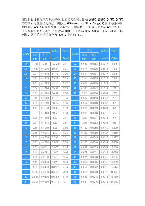
在硬件设计和线缆选型过程中,我们经常会碰到诸如16AWG、18AWG、24AWG、26AWG 等等表示电缆直径的方法。
实际上AWG(American Wire Gauge)是美制电线标准的简称,AWG值是导线厚度(以英寸计)的函数。
一般以下表表示AWG与公制、英制单位的对照。
其中,4/0表示0000,3/0表示000,2/0表示00,1/0表示0。
例如,常用的电话线直径为26AWG,约为0.4mm。
由表中归纳出的AWG与英寸的关系如下:AWG = A lg inch - B其中,A=-19.93156857,B=9.73724。
11:18:05 UTC+0800Thu Dec 27 2007口决::《10下五,100上二,25,35四三界,70,95两倍半,穿管,温度八九折,铜线升级算,裸线加一半。
》绝缘导线载流量估算铝芯绝缘导线载流量与截面的倍数关系导线截面(mm 2 ) 1 1.5 2.5 4 6 10 16 25 3 5 50 70 95 120载流是截面倍数 9 8 7 6 5 4 3.5 3 2.5载流量(A) 9 14 23 32 48 60 90 100 123 150 210 238 300估算口诀:二点五下乘以九,往上减一顺号走。
三十五乘三点五,双双成组减点五。
条件有变加折算,高温九折铜升级。
穿管根数二三四,八七六折满载流。
说明:(1)本节口诀对各种绝缘线(橡皮和塑料绝缘线)的载流量(安全电流)不是直接指出,而是“截面乘上一定的倍数”来表示,通过心算而得。
由表5 3可以看出:倍数随截面的增大而减小。
“二点五下乘以九,往上减一顺号走”说的是2.5mm’及以下的各种截面铝芯绝缘线,其载流量约为截面数的9倍。
如2.5mm’导线,载流量为2.5×9=22.5(A)。
从4mm’及以上导线的载流量和截面数的倍数关系是顺着线号往上排,倍数逐次减l,即4×8、6×7、10×6、16×5、25×4。
在硬件设计和线缆选型过程中,我们经常会碰到诸如16AWG、18AWG、24AWG、26AWG 等等表示电缆直径的方法。
实际上AWG(American Wire Gauge)是美制电线标准的简称,AWG值是导线厚度(以英寸计)的函数。
一般以下表表示AWG与公制、英制单位的对照。
其中,4/0表示0000,3/0表示000,2/0表示00,1/0表示0。
例如,常用的电话线直径为26AWG,约为0.4mm。
由表中归纳出的AWG与英寸的关系如下:AWG = A lg inch - B其中,A=-19.93156857,B=9.73724。
11:18:05 UTC+0800Thu Dec 27 2007口决::《10下五,100上二,25,35四三界,70,95两倍半,穿管,温度八九折,铜线升级算,裸线加一半。
》绝缘导线载流量估算铝芯绝缘导线载流量与截面的倍数关系导线截面(mm 2 ) 1 1.5 2.5 4 6 10 16 25 3 5 50 70 95 120载流是截面倍数 9 8 7 6 5 4 3.5 3 2.5载流量(A) 9 14 23 32 48 60 90 100 123 150 210 238 300估算口诀:二点五下乘以九,往上减一顺号走。
三十五乘三点五,双双成组减点五。
条件有变加折算,高温九折铜升级。
穿管根数二三四,八七六折满载流。
说明:(1)本节口诀对各种绝缘线(橡皮和塑料绝缘线)的载流量(安全电流)不是直接指出,而是“截面乘上一定的倍数”来表示,通过心算而得。
由表5 3可以看出:倍数随截面的增大而减小。
“二点五下乘以九,往上减一顺号走”说的是2.5mm’及以下的各种截面铝芯绝缘线,其载流量约为截面数的9倍。
如2.5mm’导线,载流量为2.5×9=22.5(A)。
从4mm’及以上导线的载流量和截面数的倍数关系是顺着线号往上排,倍数逐次减l,即4×8、6×7、10×6、16×5、25×4。

G-美国线规(AWG)与公制、英制单位的对应表格什么是AWG?在与众多客户洽谈的时候,很多朋友都提到这个问题。
为此,特别整理了该信息以方便更多朋友(American Wire Gauge)其实是美制电线标准的简称,AWG 值是导线厚度(以英寸计)的函数。
们的查阅!AWG 外径外径AWG 公制mm英制inch 截面积(mm2)电阻值(Ω/km)AWG公制mm 英制inch 截面积 (mm2) 电阻值(Ω/km) 11.680.46107.220.17 22 0.6430.02530.3247 54.3 10.40 0.4096 85.010.21 23 0.5740.02260.2588 48.5 9.270.3648 67.430.26 24 0.5110.02010.2047 89.4 8.250.324953.490.3325 0.44 0.01790.162479.61 7.35 0.289342.410.4226 0.404 0.01590.1281143 2 6.540.257633.620.5327 0.3610.01420.10211283 5.830.229426.670.6628 0.32 0.01260.08042274 5.190.204321.150.8429 0.287 0.01130.06472895 4.62 0.1819 16.77 1.06 30 0.2540.01000.0507 361 6 4.11 0.1620 13.30 1.33 31 0.2260.00890.0401 321 7 3.67 0.1443 10.55 1.68 32 0.2030.00800.0316 583 8 3.26 0.1285 8.37 2.11 33 0.180.00710.0255 944 9 2.91 0.1144 6.63 2.67 34 0.16 0.00630.020195610 2.590.1019 5.26 3.3635 0.142 1,200 0.00560.0169112.300.0907 4.17 4.2436 0.1270.00500.01271,530123.332 2.050.0808 5.3137 0.1140.00450.00981,37713 1.820.0720 2.627 6.6938 0.1020.00400.00812,40014 1.630.0641 2.0758.4539 0.0890.00350.00622,10015 1.45 0.0571 1.64610.6 40 0.0790.00310.0049 4,080 16 1.29 0.0508 1.31813.5 41 0.0710.00280.0040 3,685 17 1.15 0.0453 1.02616.3 42 0.0640.00250.0032 6,300 18 1.02 0.0403 0.810721.4 43 0.0560.00220.0025 5,544 19 0.912 0.0359 0.566726.9 44 0.0510.00200.0020 10,20020 0.8130.03200.518933.945 0.0460.00180.00169,180 210.7240.02850.411642.74616,3000.0410.00160.0013其中,4/0表示0000,3/0表示000,2/0表示00,1/0表示0。