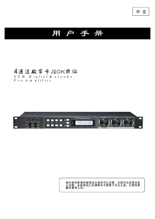
K-LEM 台湾歌利来 KSP-4600S DSP数字卡拉OK前级说明书
- 格式:pdf
- 大小:7.22 MB
- 文档页数:31
6
可编辑话筒、效果、音乐、系统菜单,以及存储和调用用户及出厂预设。
后背板说明
12
34
5
6
7
8
1 电源线 电 源 输 入: A C ~ 2 2 0 V , 5 0 H z
2 电源开关
3 R S 2 3 2接 口 用 来 与P C /点 歌 系 统 连 接 , 进 行 远 程 控 制
4 录音输出端子 可连接到录音设备,进行话筒和音乐的同步录制
ECHO EQ1 Q:0.40PK
F:54.4
G:0.0
按三次 “▼”键可 以 调整ECH O的P E Q参 数,E CHO的PE Q数 量EQ1 - 5可 选,P EQ的频 率F、类型 (P K参 量均衡\ LS低架\ HS高架\ LC低切\ HC高切 )、Q值 、 以 及增 益G可 调。
用户手册
4, 用 户 预 设 模 式 切 换 键 U 0 1 - U 0 6为 用户预 设 模式, 可 以调用 任 意模 式 来使用 。
5, 音 乐 变 调 按 键 “b”1 -5为5阶降 调,“ ” 为 标准调 , “#”1- 5为5阶 升调。
功能方框图
MIC A MIC B
VOD COAX OPTICAL
LEVEL LEVEL
BBE 激励
BBE 激励 BBE 激励
PEQ
PEQ
GATE 噪声门 GATE 噪声门
GATE 噪声门
MUSIC/MIC/EFFECT 人 声/音 乐/效 果
MUSIC/MIC/EFFECT 人 声/音 乐/效 果
MUSIC/MIC/EFFECT 人 声/音 乐/效 果
MUSIC/MIC/EFFECT 人 声/音 乐/效 果
前面板说明
6
54
3
2
1
1 U S B端 口 用 来 与 电 脑 连 接P C软 件 控 制 机 器 使 用 。
2 效 果/话 筒/音 乐 总 音 量 调 节 可控制效果量的大小及话筒和音乐音量的大小。
3
显示所有操作功能菜单。
4 红外遥控接收窗口
用户手册 5 主菜单翻页键,退出键
进入菜单后,按"▲▼ "键可上下进行翻页,按EXIT键退出。
调用键
按一次 “调用 ” 键和旋 转 “效果/编 辑 ”编码 器 可选择 调 用预设 程 序U0 1 - U 1 6或 原厂预 设程序F 01,再 按 一次为 确 认调用 。
效果键
按一下 “效果 ” 键进入E CHO的参 数 界面: 回 声增益 调 节范围 是0 - 1 00;预 延 时时间0 -250mS可调 ; 模式选 择 有单回 声 (MO N O )和 立体声 (S T E REO)两种 。
5 立体声辅助,中置,超低音输出 可 连 接 立 体 声 环 绕,中 置,超 低 音 扩 声 系 统
6
7 音频输入端口 音 频 输 入 可 手 动 切 换 至V O D , B G M ,光 纤,同 轴 输 入 通 道,选 自 动 时V O D和B G M会 相 互 切 换
8 话筒输入插座 话 筒 输 入 通 道 ,A , B两 路 话 筒 可 单 独 处 理 , 同 时 可 接 四 只 话 筒 输 入
DSP数字卡拉OK前级
版本:V1 . 1
用户手册
产品功能 ..............................................1 前面板说明 ............................................1 后背板说明 ............................................2 遥控器说明 ............................................3 功能方框图 ............................................3 操作指导 ..............................................4-7 PC软件 ................................................8 USB数据线连机步骤 ......................................8 RS232转USB数据线连机步骤 ...............................9-13 无线WIFI连机步骤 ......................................13-15 PC软件界面 ............... .............................16 PC软件操作说明 ........................................17-24 技术指标 ..............................................25 配件清单 ..............................................25 上位机串行口通信协议 ...................................26-28 注意事项 ..............................................29
COMP 压缩器PHASE Nhomakorabea位MUTE 静音
COMP 压缩器
PHASE 相位
MUTE 静音
COMP 压缩器
PHASE 相位
MUTE 静音
COMP 压缩器
PHASE 相位
MUTE 静音
操作指导
用户手册
主画面
KTV1 EFF: 50
MUS: 0 MIC: 0
开机自 检结束 后 ,LC D显 示预设 信 息。有 “K T V1”出 厂预 设 和“U0 1 - U 1 6”1 6个 用户预 设可选 择 。“M”显 示 当前音 乐 音量值; "E"显示 当 前效果 音 量值; “M I C” 显示当前话筒总音量大小。
M1抒情、M2唱将、M3 K TV、M4舞曲模式调用键
Load Preset U01 Loading......
按一次 按键直 接 可以调 用U 01-04用户 预设模 式 。
保存键
Store U01
Preset Default
按“保 存”键 可 保存预 设 程序, 旋 转“效 果/编 辑”编 码 器选择 要 保存的 位 置U0 1 - U 1 6。
遥控器说明
用户手册
1
2 3 4 5
1, 标 准 预 设 控 制 键 F O 1可以切 换 至出厂 预 设K T V 1模 式。
2, 音 量 控 制 键 可 以调整MUSIC,EF F E C T,M I C的 音量大 小 。
3, 输 入 切 换 及 静 音 控 制 键 I N P U T键 可切 换 音源的 输 入通道 和 输入模 式 ,M U T E键 可控制 静 音。
RVB PREDLY: 50mS TIME: 1.96s G:30
按四次 “▼”键进 入R E VERB参数 调整界 面 :预延 时 调节范 围 是0- 2 5 0 m s; 时间 调节范 围是0- 4 s, 增益 调 节范围 是0 -100。
REVERB EXCITER:32
SP:0mS
REF:12
Preset Naming [Default]
连续按 下“效 果/编 辑 ”编 码 器可编 辑 要保存 文 件的名 称 。
Preset Naming Saving...
Load
Preset
F01 KTV1
ECHO PDLY: 0mS MODE: MONO G:80
直至出 现“Y”按确 认 后即 可 保存。
选,以及 延 时 , 重 复 , 预 延 时 参 数 独 立 可 调 ;R E V E R B带5段参量均衡(可做高低切),有预延时,时间,激励,空间,反射 参数调整;另外还有直达声效果处理。 *音乐通道 具 有 总 音 量 控 制 , 限 制 器 , 噪 声 门 , 可 选 类型的低切,10段参量均衡,激励(参数可调可保存),升降 调等处理模 块。2路立 体 声 音 乐 输 入, 其 中B G M和V O D具 有 单 独 输 入音量控制,可选择自动和手动切换模式。还配有1路光纤输入和1路同轴 输入。 * 5.1声道输 出 : 左 右 输 出 , 中 直 输 出 , 辅 助 输 出 , 超 低 音输出。 *左右输出 具 有 独 立 音 量 控 制 , 静 音 , 相 位 , 压 缩 ( 参数可调),9段参量均衡(可做高低切),左右延时等处理模块。 *中置输出 具 有 独 立 音 量 控 制 , 静 音 , 相 位 , 压 缩 ( 参 数可调),6段参量均衡(可做高低切),延时等处理模块。 *辅 助 输 出 具 有 独 立 音 量 控 制 , 静 音 , 相 位 , 压 缩 ( 参 数 可 调 ) ,6段 参 量 均 衡 ( 可 做 高 低 切 ) , 左 右 延 时 等 处 理 模 块 。 *超 低 音 输 出 具 有 独 立 音 量 控 制 , 静 音 , 相 位 , 压 缩 ( 参 数 可 调 ) ,5段 参 量 均 衡 , 可 选 类 型 的 低 切 , 高 切 , 延 时 等 处 理 模 块,另A G C自动增益控制功能(通常所说当话筒关闭后,系统将自动进入热舞状态),输出增益可接受话筒控制进行衰减, 且衰减量连续可调。 *输出通道还 具 有 舞 曲 和唱 歌 设 定 功 能 , 有 手 动 和 自 动选择模式,通常在自动模式下,当话筒打开后进入唱歌模式,当话筒关 闭后进入舞曲模式。 *2路话筒处 理 通 道 可 接 不 同 类 型 的 话 筒 , 比 如 : 无 线 话 筒,有限话筒,落地式拖杆话筒,针对不同曲线做不同修 饰,这样可 以将话筒音色做到极致。 *整机工作有 三 种 状 态 ,断 电 记 忆 , 断 电 不 记 忆 和 断 电不记忆且每次开机默认U01参数,适合不同人员在不同情况下使用。 *美观且操 作 简 便 的P C软 件 控 制 界 面 , 而 且 在 面 板 上 也可基本实现PC界面上的功能操作。面板和软件都具有操作锁功能,面板 带USB调 试 端 口 , 后 面 带R S 2 3 2中 控 控 制 端 口 , 也 可 以 接无线WIFI控制盒,实现远距离无线控制,系统操作更安全 方便。 *高档LCD屏 幕 显 示 , 带 红 外 遥 控 功 能 ,1个 工 厂 预 设 和16个用户预设,有多种推荐的效果值可供选择,可以保存和调用单独预 设文件,也可进行整机数据上传和下载。
可编辑话筒、效果、音乐、系统菜单,以及存储和调用用户及出厂预设。
后背板说明
12
34
5
6
7
8
1 电源线 电 源 输 入: A C ~ 2 2 0 V , 5 0 H z
2 电源开关
3 R S 2 3 2接 口 用 来 与P C /点 歌 系 统 连 接 , 进 行 远 程 控 制
4 录音输出端子 可连接到录音设备,进行话筒和音乐的同步录制
ECHO EQ1 Q:0.40PK
F:54.4
G:0.0
按三次 “▼”键可 以 调整ECH O的P E Q参 数,E CHO的PE Q数 量EQ1 - 5可 选,P EQ的频 率F、类型 (P K参 量均衡\ LS低架\ HS高架\ LC低切\ HC高切 )、Q值 、 以 及增 益G可 调。
用户手册
4, 用 户 预 设 模 式 切 换 键 U 0 1 - U 0 6为 用户预 设 模式, 可 以调用 任 意模 式 来使用 。
5, 音 乐 变 调 按 键 “b”1 -5为5阶降 调,“ ” 为 标准调 , “#”1- 5为5阶 升调。
功能方框图
MIC A MIC B
VOD COAX OPTICAL
LEVEL LEVEL
BBE 激励
BBE 激励 BBE 激励
PEQ
PEQ
GATE 噪声门 GATE 噪声门
GATE 噪声门
MUSIC/MIC/EFFECT 人 声/音 乐/效 果
MUSIC/MIC/EFFECT 人 声/音 乐/效 果
MUSIC/MIC/EFFECT 人 声/音 乐/效 果
MUSIC/MIC/EFFECT 人 声/音 乐/效 果
前面板说明
6
54
3
2
1
1 U S B端 口 用 来 与 电 脑 连 接P C软 件 控 制 机 器 使 用 。
2 效 果/话 筒/音 乐 总 音 量 调 节 可控制效果量的大小及话筒和音乐音量的大小。
3
显示所有操作功能菜单。
4 红外遥控接收窗口
用户手册 5 主菜单翻页键,退出键
进入菜单后,按"▲▼ "键可上下进行翻页,按EXIT键退出。
调用键
按一次 “调用 ” 键和旋 转 “效果/编 辑 ”编码 器 可选择 调 用预设 程 序U0 1 - U 1 6或 原厂预 设程序F 01,再 按 一次为 确 认调用 。
效果键
按一下 “效果 ” 键进入E CHO的参 数 界面: 回 声增益 调 节范围 是0 - 1 00;预 延 时时间0 -250mS可调 ; 模式选 择 有单回 声 (MO N O )和 立体声 (S T E REO)两种 。
5 立体声辅助,中置,超低音输出 可 连 接 立 体 声 环 绕,中 置,超 低 音 扩 声 系 统
6
7 音频输入端口 音 频 输 入 可 手 动 切 换 至V O D , B G M ,光 纤,同 轴 输 入 通 道,选 自 动 时V O D和B G M会 相 互 切 换
8 话筒输入插座 话 筒 输 入 通 道 ,A , B两 路 话 筒 可 单 独 处 理 , 同 时 可 接 四 只 话 筒 输 入
DSP数字卡拉OK前级
版本:V1 . 1
用户手册
产品功能 ..............................................1 前面板说明 ............................................1 后背板说明 ............................................2 遥控器说明 ............................................3 功能方框图 ............................................3 操作指导 ..............................................4-7 PC软件 ................................................8 USB数据线连机步骤 ......................................8 RS232转USB数据线连机步骤 ...............................9-13 无线WIFI连机步骤 ......................................13-15 PC软件界面 ............... .............................16 PC软件操作说明 ........................................17-24 技术指标 ..............................................25 配件清单 ..............................................25 上位机串行口通信协议 ...................................26-28 注意事项 ..............................................29
COMP 压缩器PHASE Nhomakorabea位MUTE 静音
COMP 压缩器
PHASE 相位
MUTE 静音
COMP 压缩器
PHASE 相位
MUTE 静音
COMP 压缩器
PHASE 相位
MUTE 静音
操作指导
用户手册
主画面
KTV1 EFF: 50
MUS: 0 MIC: 0
开机自 检结束 后 ,LC D显 示预设 信 息。有 “K T V1”出 厂预 设 和“U0 1 - U 1 6”1 6个 用户预 设可选 择 。“M”显 示 当前音 乐 音量值; "E"显示 当 前效果 音 量值; “M I C” 显示当前话筒总音量大小。
M1抒情、M2唱将、M3 K TV、M4舞曲模式调用键
Load Preset U01 Loading......
按一次 按键直 接 可以调 用U 01-04用户 预设模 式 。
保存键
Store U01
Preset Default
按“保 存”键 可 保存预 设 程序, 旋 转“效 果/编 辑”编 码 器选择 要 保存的 位 置U0 1 - U 1 6。
遥控器说明
用户手册
1
2 3 4 5
1, 标 准 预 设 控 制 键 F O 1可以切 换 至出厂 预 设K T V 1模 式。
2, 音 量 控 制 键 可 以调整MUSIC,EF F E C T,M I C的 音量大 小 。
3, 输 入 切 换 及 静 音 控 制 键 I N P U T键 可切 换 音源的 输 入通道 和 输入模 式 ,M U T E键 可控制 静 音。
RVB PREDLY: 50mS TIME: 1.96s G:30
按四次 “▼”键进 入R E VERB参数 调整界 面 :预延 时 调节范 围 是0- 2 5 0 m s; 时间 调节范 围是0- 4 s, 增益 调 节范围 是0 -100。
REVERB EXCITER:32
SP:0mS
REF:12
Preset Naming [Default]
连续按 下“效 果/编 辑 ”编 码 器可编 辑 要保存 文 件的名 称 。
Preset Naming Saving...
Load
Preset
F01 KTV1
ECHO PDLY: 0mS MODE: MONO G:80
直至出 现“Y”按确 认 后即 可 保存。
选,以及 延 时 , 重 复 , 预 延 时 参 数 独 立 可 调 ;R E V E R B带5段参量均衡(可做高低切),有预延时,时间,激励,空间,反射 参数调整;另外还有直达声效果处理。 *音乐通道 具 有 总 音 量 控 制 , 限 制 器 , 噪 声 门 , 可 选 类型的低切,10段参量均衡,激励(参数可调可保存),升降 调等处理模 块。2路立 体 声 音 乐 输 入, 其 中B G M和V O D具 有 单 独 输 入音量控制,可选择自动和手动切换模式。还配有1路光纤输入和1路同轴 输入。 * 5.1声道输 出 : 左 右 输 出 , 中 直 输 出 , 辅 助 输 出 , 超 低 音输出。 *左右输出 具 有 独 立 音 量 控 制 , 静 音 , 相 位 , 压 缩 ( 参数可调),9段参量均衡(可做高低切),左右延时等处理模块。 *中置输出 具 有 独 立 音 量 控 制 , 静 音 , 相 位 , 压 缩 ( 参 数可调),6段参量均衡(可做高低切),延时等处理模块。 *辅 助 输 出 具 有 独 立 音 量 控 制 , 静 音 , 相 位 , 压 缩 ( 参 数 可 调 ) ,6段 参 量 均 衡 ( 可 做 高 低 切 ) , 左 右 延 时 等 处 理 模 块 。 *超 低 音 输 出 具 有 独 立 音 量 控 制 , 静 音 , 相 位 , 压 缩 ( 参 数 可 调 ) ,5段 参 量 均 衡 , 可 选 类 型 的 低 切 , 高 切 , 延 时 等 处 理 模 块,另A G C自动增益控制功能(通常所说当话筒关闭后,系统将自动进入热舞状态),输出增益可接受话筒控制进行衰减, 且衰减量连续可调。 *输出通道还 具 有 舞 曲 和唱 歌 设 定 功 能 , 有 手 动 和 自 动选择模式,通常在自动模式下,当话筒打开后进入唱歌模式,当话筒关 闭后进入舞曲模式。 *2路话筒处 理 通 道 可 接 不 同 类 型 的 话 筒 , 比 如 : 无 线 话 筒,有限话筒,落地式拖杆话筒,针对不同曲线做不同修 饰,这样可 以将话筒音色做到极致。 *整机工作有 三 种 状 态 ,断 电 记 忆 , 断 电 不 记 忆 和 断 电不记忆且每次开机默认U01参数,适合不同人员在不同情况下使用。 *美观且操 作 简 便 的P C软 件 控 制 界 面 , 而 且 在 面 板 上 也可基本实现PC界面上的功能操作。面板和软件都具有操作锁功能,面板 带USB调 试 端 口 , 后 面 带R S 2 3 2中 控 控 制 端 口 , 也 可 以 接无线WIFI控制盒,实现远距离无线控制,系统操作更安全 方便。 *高档LCD屏 幕 显 示 , 带 红 外 遥 控 功 能 ,1个 工 厂 预 设 和16个用户预设,有多种推荐的效果值可供选择,可以保存和调用单独预 设文件,也可进行整机数据上传和下载。