WD-4000控制器说明书
- 格式:doc
- 大小:122.00 KB
- 文档页数:20


WD-4000变频恒压供水电脑控制器使用手册目录系统概述 (2)主要性能指标 (2)安装尺寸和接线端子说明 (3)操作面板指示及参数设定说明 (4)参数列表及参数出厂默认值 (6)恢复系统参数出厂值 (6)系统参数功能详细说明 (9)故障显示代码说明 (16)外部输入信号端子说明 (16)系统当前时间的调整 (16)手动临时开机的调整 (16)外部输出端子与部分变频器端子的连接表 (17)控制器与压力变送器的连接 (18)RS485远程通讯接口 (18)一、系统概述WD-4000系列微电脑变频供水/补水控制器是专为变频恒压供水系统和锅炉及换热系统补水而设计的电脑控制器,可与各种品牌的变频器配套使用。
具有压力控制精度高、压力稳定、第二消防压力(动压)设定、系统超压泄水自动控制、设定参数密码锁定等多项功能。
二、主要性能指标1.可编程设定多种泵工作方式,最多可拖4台泵循环启动;2.可选配的RS485远程通讯接口,标准组态软件支持远程通讯;3.参数调整和设定具有密码锁定及保护功能;4.采用人工智能模糊控制算法,设定参数少,控制精度高,内带看门狗电路,采用数字滤波及多项抗干扰措施,防止软件跑飞;5.可接无源远传压力表、有源电压及电流型压力变送器;6. D/A输出控制频率电压为DC 0-10V, 也可设定为DC 0-5V;7.具有压力传感器零点和满度补偿功能;8.具有定时自动倒泵功能;9.具有第二压力(消防压力)设定和控制功能;10.具有缺水自动检测保护功能和外部输入停机保护功能;11.系统补水控制时,具有超压自动泄水控制功能;12.具有供水附属小泵控制功能,可设定小泵变频或工频模式;13.具有可选的定时自动开、关机控制功能;14.具有小流量水泵睡眠控制功能;15.具有手操器功能,可手动调节输出电压来控制变频器的频率;16.可代替电接点压力表进行上、下限压力控制;17.具有分时分压供水控制功能,最多有六段时间控制;三、安装尺寸和接线端子说明1.控制器外形尺寸: 160mm×80mm×90mm2.控制柜面板开口尺寸151mm×75mm,面板卡入式安装。

CONTENTSPAGE Manual introduction 4 System introduction 4 System components 4 – 13 Codelock programming instructions 15 – 16 Accessories 13 – 14 Installation 14 Cable size guide 17 Testing the system 17 Panel care 17 Accessories connection guide 17 – 18 Single entrance single button audio wiring diagram 19 Single or multiple entrance, multiple button audio wiring diagram20 Single entrance video system wiring diagram 21 Multiple entrance video system wiring diagram 22 Troubleshooting guide 23The information in this manual is intended as an installation and commissioning guide for the vandal resistant 4000 Series door entry systems. This manual should be read carefully before the installation commences. Any damage caused to the equipment due to faulty installations where the information in this manual has not been followed is not the responsibility of Videx Security Ltd.VIDEX run free training courses for engineers who are not familiar with the Videx product range. Technical help is also available on 0191 224 3174 during office hours or via e-mail ***********************.This kit will enable a caller at an entrance point to signal an occupant in the dwelling by pressing a call button which will send an electronic call tone to an audio telephone. A Yellow ‘SPEAK’ LED will indicate the call has been answered and a two way conversation can take place, the occupant can release an electric lock release by pressing a button on the telephone base unit. The output for the lock is a dry contact relay allowing any type of lock can be used with an appropriate PSU. If this system is to be used with a gate, the dry contact output can be used to trigger the gate control board. DDA features such as a ‘SPEAK’ LED, ‘DOOR OPEN’ LED and reassurance tones are standard on this system. The system is available modular and non-modular. The modular system allows a door panel to be assembled from a range of modules including amplifiers, button modules, camera modules and access control modules. The modules are then assembled into the 4000 Series frames using the brackets and screws supplied.The system comprises of door panels, telephones/videophones and power supplies. Relays will also be used on multiple door video systems but there are no switches required for multiple door audio systems as was the case with the older systems. The door panel may be made up of several parts including modules and a surface or flush frame. These modules are easily assembled into the frames using the brackets and screws supplied with each module. The order in which the modules fit into the frames is down to customer taste but we would suggest keeping the amplifier module as far from the microphone holder as possible to avoid Larsen affect.The vandal resistant door panel will consist of an amplifier, buttons, frame/back box and optional items such as camera and access control features (Codelock, proximity etc). Frame sizes are available for 1, 2, 4, 6 and 9 modules in both surface and flush fitting configurations. Call buttons can be engraved to suite the apartment numbers.Speech volume adjustments are carried out at the door panel using a small trimmer driver. CAMERA (Art.VR4KCMM – Mono & Art.VR4KCMC - Colour)The camera module is available in both mono and colour and can be set for either coax installations or non-coax installations. A tilt adjustment is available on the rear of the Connection FunctionNOTE: ANY 1A 13.8Vdc PSU can be used with this amplifier as an alternative to the 520M.20Vdc 800mA continuous 1A surge PSU and is used to power the videophones and camera on video systems and can also be used as a booster supply or when more than two videophones are required in an apartment. This power supply only has an output when either a 0V is applied to –C or when a voltage is applied to Connection Function5 5Art.3312DIP SWITCH SETTINGSThe Art.3312 (3412 for colour) includes a lock release push button, camera recall button and three dry contact push to make spare push buttons for other services. Coax and non-coax video can be used by setting the relevant dip-switches. An Art.3980 back plate is required with this videophone. CONNECTIONS:-Terminal Signal Function1 +12V Out +12V out to power video splitter2 TV1 Camera recall (● Button)3 TV2 Spare button (●● Button)4 1 +20V power input5 2 Door release command6 3 Transmit speech to door panel7 4 Receive speech from door panel8 5 Speech Ground9 6 Video power ground 107 Local call tone input11 V/V1 Coax centre core or balance video –sync (V1) 12 M/V2 Coax Screen or balanced video +sync (V2)13R Speech common for intercommunicating systems 14C Call tone input 15- Speech ground for intercommunicating systems 16T Common of spare buttons17 1T Spare button 18 2T Spare button 9 + Coax Or 11 coresThe Art.3313 (3413 for colour) includes a lock release push button and two dry contact push to make spare push buttons for other services. An Art.3980 back plate is required with this videophone. CONNECTIONS:- Terminal Signal Function 1 +12V OUT +12V out to power video splitter 2 TV1 Camera recall (● Button)3TV2 Camera recall or switch to terminal 16 (Dip switch dependant) (●● Button) 41 +20V power input 52 Door release command 63 Transmit speech to door panel7 4 Receive speech from door panel 8 6 0V (Ground) 9 5 Not used107 Local call tone input 11 V/V1 Coaxcentre core or non-coax sync- (V1) 12M/V2 Coax Screen or non-coax Sync+ (V2)13 D Switched +12 for door open LED 14C Select input to switch on videophone15 C1 Call tone input 16 T Common of spare buttons ●●, ● and S171T Spare button (S button) 18+12V IN +12V to power videophone privacy DIP SWITCH SETTINGS 8 Way dip switch (Switches 1 – 5) Mute Duration timeTime 1 2 3 4 5 15 Minutes ON OFF OFF OFF OFF 30 Minutes OFF ON OFF OFF OFF 2 Hours OFF OFF ON OFF OFF 4 Hours OFF OFF OFF ON OFF 8 Hours OFF OFF OFF OFF ON 3 Way Dip Switch VIDEO MODE continued Switch 1 2 3 Coax OFF OFF OFF Non-Coax ON ON ON8 Way dip switch (Switch 6) Mute LED Switch 6 Fixed OFF Flashing ON 8 Way dip switch (Switches 7 & 8) °° Button Operation Switch 7 8 Camera recall ON OFF Dry contact OFF ON 4 Way Dip Switch (Switches 1 & 2) S Button Operation Switch 1 2 Camera recall ON OFF Dry contact OFF ON 4 Way Dip Switch (Switches 3 & 4) VIDEO MODE Switch 3 4 Coax ON ON Non-Coax OFF OFF10 + CoaxOr12 coresCABLE SIZE GUIDESuitable cables for this system are CW1308 and YY cable (Other similar cables are also suitable) Care should be taken to avoid excessive voltage drop. Follow the guide lines below.Connections from door panel to telephones/videophones. Connections 50m 100m 200m 300m 400mPower0.35mm² 0. 5mm² 0.75mm² 1.00mm² 1.5mm² All Others0.25mm² 0.35mm² 0.5mm² 0.75mm² 1.0mm² Maximum acceptable resistance for power terminals 5Ω, all others 10ΩConnections for power supply output to door panel and lock release connections. Theseconnections are shown heavily outlined on the wiring diagram.50m 100mConnections0.5mm² 0.75mm² The power supply should be located as close to the door panel as possible for best performance.Maximum acceptable resistance for above cables 3Ω- Check all the connections have been made correctly and dip-switches have been set and then power up the system.- Call the apartments. Check for call to all apartments, speech in both directions and lock release and correct operation of the SPEAK & DOOR OPEN LED’s.- If the volume of speech needs to be adjusted, this can be done by adjusting the presets on the rear of the amplifier at the door panel.The door panel is manufactured from 12 Gauge 304 grade stainless steel. It is important that the facia is cleaned on regular occasions to prevent dirt build up and tarnishing of the metal. A general household metal polish can be used but care should be taken to follow the grain of the metal when polishing and also avoid any polish build up around the call button which may prevent the button from operating correctly.ES/1 Extension Strobe512A Extension sounderAdding the 4800 codelock to a panelSYMPTOM TESTNo speech from the door panel to the telephone.Check terminal 2 on the amplifier for continuity toterminal 2 on the telephone.Check the voltage drops to approx. 1Vdc after the handset is lifted. (If not try another telephone)If all else fails try another amplifier at the door stationNo speech from the telephone to the door panel.Check terminal 1 on the door panel amplifier forcontinuity back to terminal 1 on the telephone.Check the voltage drops to approx. 4Vdc after the handset is lifted. (If not try another telephone)If all else fails try another amplifier at the door stationNo speech in either directionCheck the 315mA fuse in the power supplyCheck for 12Vdc across terminals + & - on the door panel amplifier. This should be there all the time and comes directly from the PSU.Lock will not operate from telephoneCheck terminal 5 on the telephone. This terminal shorts to terminal 3 of the telephone when pressed (Becomes 0V) and sends a 0V to terminal 5 on the VX136 amplifier at the door panel which in turn triggers the relayCheck the relay on the VX136 is energising. Use a continuity meter to check the switching.Nothing happens when call button is pressedCheck the common of the button is connected to Ton the VX136Check continuity from the other side of the call button to terminal 4 on the handsetHum on the speech linesEnsure all intercom cables do not run close to higher voltage cablesTry another amplifier at the door panel.Rolling or poor video pictureCheck camera jumper setting is set correctly Check end of line resistors are fitted on last 316video splitter (Non-coax) or end of line resistors plus termination resistors on any unused outputs of the 894 video splitter (Coax).Check dip-switches are set correctly on videophone On multiple door systems, check that only onecamera is being switched on at a time. (When camera is switched on it will have 20Vdc across +&-Camera recall does not workCheck terminal TV1 (● button) wire for continuity to T of relevant door panel.On multiple door systems, lifting the handset causes feedback or speech from all doors at the same time.Dip switch 4 of the amplifier is switched on. This switch can only be on, for one door systems.Remember to power down after making the change.Northern OfficeVidex Security LtdUnit 4-7 Chillingham Ind. Est. Newcastle Upon TyneNE6 2XXTEL 0870 300 1240FAX 0191 224 5678 Southern Office1 OspreyTrinity ParkTrinity WayLondonE4 8TDFAX 0208 523 5825 TECHNICAL SUPPORT***********************TEL 0191 224 3174FAX 0191 224 4938。
L-4000智能控制器使用说明L4000智能控制器基本参数工作电压:220V外型尺寸:390*235*80 (H*W*D)最大负载:6000W单路负载:可调灯光1500W 开关灯光3000W功能简介L-4000灯光/空调智能控制器是专为KTV设计的一款具备灯光亮度调节、中央空调控制、可编程的智能型灯光/空调控制器。
1、设有6路大功率可调光及4路大功率继电器,满足各种灯光应用的需求2、可直接通过串口与机顶盒或电脑连接3、可直接连接灯光控板,脱离点歌系统及中控盒独立运行4、可对任一模式下的灯光状态进行编程,实现任意灯光搭配5、灯光控制器上可直接按键操作选择灯光模式及调节灯光亮度6、灯光亮度均衡,通过在不同模式下设置不同的亮度,实现场景效果切换,减少了灯光的开关次数,延长灯光使用寿命7、可外接遥控器对灯光进行遥控控制(选配)8、中央空调智能控制,配合点歌系统可实现远程开关空调9、配盒空调墙板通过温度探测,可智能控制风机及阀门的开关,减少能源浪费10、设有2组空调控制11、根据室温与设定温的比对,自动调节风速12、采用串口光电隔离技术,避免设备间的互相干扰灯光控制的设置一、灯光模式对应组的编程先关闭灯光控制器电源,按住设置及确认键不放,打开电源,等待约1秒,灯光控制器显示01并闪烁,表示01组,按△或▽键选择所要编程的组。
1、选择需要编程的组按△或▽键选择需要编程的组,按确认键进入该组编程设置;2、设置该组对各路灯光的控制状态数码管显示J1,对应指示灯指示出该模式下灯光的控制状态,亮表示控制,闪烁表示不控制,不亮表示强制关。
按▽键选择要设置的灯光,J1-JA表示灯光控制器的10路,按设置键进行设置,按确认键进入下一步设置;3、设置组的开关模式显示H1表示固定模式,显示H0表示开关模式(固定模式:例如,当按K歌时1、2、3路亮,再次按K歌时还是1、2、3路亮;开关模式:例如,当按K歌时1、2、3路亮,再次按K歌时1、2、3路灭),按设置键进行选择,按确认键进入下一步设置;4、设置组的亮度继承方式显示L1表示固定亮度,显示L0表示继承亮度(固定亮度,例如:进入K歌模式后,将其亮度由60调到80,第二次进入K歌模式时它的默认亮度还原为60;继承亮度,例如:进入K歌模式后,将其亮度由60调到80,第二次进入K歌模式时它的默认亮度为80)。

e-mail:**************For latest product manuals: CN4000 SERIESTemperature ControllersShop online at User’s G ui d e***********************Servicing North America:U.S.A. Omega Engineering, Inc.Headquarters: Toll-Free: 1-800-826-6342 (USA & Canada only)Customer Service: 1-800-622-2378 (USA & Canada only)Engineering Service: 1-800-872-9436 (USA & Canada only)Tel: (203) 359-1660 Fax: (203) 359-7700e-mail:**************For Other Locations Visit /worldwideThe information contained in this document is believed to be correct, but OMEGA accepts no liability for any errors it contains, and reserves the right to alter specifications without notice.CONTENTSMODEL CONFIGURATION (2)SPECIFICATIONS (3)PARAMETER AND SETTING (4)SYMBOL DESCRIPTIONS (7)INSTRUMENT INSTALLATION AND WIRING (8)DISPLAY AND OPERATIONS (9)OPERATION DESCRIPTION (10)MODEL CONFIGURATIONModel DescriptionCN4116 (*)-(**)-(***) 1/16 DIN controllerCN4216 (*)-(**)-(***) 1/16 DIN controller, with 0.0 decimalCN414 (*)-(**)-(***) 1/4 DIN controllerCN424 (*)-(**)-(***) 1/4 DIN controller, with 0.0 decimalCN418V (*)-(**)-(***) 1/8 DIN Vertical controllerCN428V (*)-(**)-(***) 1/8 DIN Vertical controller, with 0.0 decimalCN418H (*)-(**)-(***) 1/8 DIN Horizontal controllerCN428H (*)-(**)-(***) 1/8 DIN Horizontal controller, with 0.0 decimal*Specify controlling output code from Output Options table below**Specify alarm code from Alarm Options table below***Low voltage power supply option (-LV)Controlling Output OptionsOption Type CodeRelay -R1DC SSR driver -DC1Alarming Output OptionsOption Type CodeRelay -R2DC SSR driver -DC2Low voltage power supply optionHz50/60AC/DC,-LV 24VSPECIFICATIONSThermocouple RTD Input TypeK S R E J N PT100Range ℃/ ℉0 to1300 ℃32 to 2372 ℉0 to1700℃32 to 3092 ℉0 to1600℃32 to 2412 ℉0 to1000℃32 to 1832 ℉0 to1200℃32 to 2192 ℉0 to 1300℃32 to 2372 ℉-200 to 800℃-328 to 1472 ℉Accuracy:CN 4116/CN414/CN4180.3%FS ± 1℃/1.8°FCN4216/CN424/CN428 0.3%FS ± 0.1℃/0.18°FTemperature Display ResolutionCN 4116/CN414/CN4181℃/1℉CN4216/CN424/CN4280.1℃/0.1℉ON / OFF ControlControl MethodAI PID Control with Auto Tuning (AT)Relay Output (1A/250VAC)Output TypeVoltage Output for SSR(12V/30mA)Limit High / LowAlarm(Modularization) High deviation/Low deviation100~240VAC (-15%, +10%), or 24VDC Supply Voltage50 to 60HzPower Consumption ≦ 3WOperating EnvironmentsTemperature: -10 to +60℃ / 14 to 140℉Humidity: 0~90RH%Electromagnetic compatibility (EMC) IEC61000-4-4: ± 4KV/5KHz IEC61000-4-5: 4KVPARAMETER AND SETTINGField parameter table (Primary parameters)Code Description Remarks SettingRange DefaultHIAL High limit alarm Alarm on when PV>HIALalarm off when PV<HIAL- AHYS-999~+3000 3000LoAL Low limit alarm Alarm on when PV<LoAL;alarm off when PV>LoAL + AHYS-999~+3000 -999HdAL Deviation highalarmAlarm on when PV-SV>HdAL;alarm off when PV-SV<HdAL - AHYS-999~+3000 3000LdAL Deviation lowalarmAlarm on when PV-SV<LdAL;alarm off when PV-SV>LdAL + AHYS-999~+3000 -999Loc Parameter LockLocAutoTuningSVPrimaryParameterSecondaryParameter0 X1 X X2 X X X3 X X X X808: allow to modify data or execute ATX : not allow to modify data or execute AT0~255 0System parameter table (Secondary parameters)Scb Input Shift Parameter Scb is used to make input shift tocompensate the error produced by sensor or inputsignal itself.PV-after-compensation=PV-before-compensation + Scb.-199~+400FILt PV input filter The value of FILt will determine the ability offiltering noise.When a large value is set, the measurement inputis stabilized but the response speed is slow.Generally, if great interference exists, then youcan increase parameter “FILt” gradually to makemomentary fluctuation of measured value lessthan 2 to 5.When the meter of the instrument is beingexamined at laboratory, “FILt” should be set to 0or 1 to short the response time.0~40 1Fru Selection of powerfrequency andtemperature scale50C: 50Hz, ℃50F: 50Hz, ℉60C: 60Hz, ℃60F: 60Hz, ℉50C, 50F,60C, 60F50CSPL Low limit of SV -999~3000SPH Upper limit of SV -999~3000400SYMBOL DESCRIPTIONS Symbol DescriptionorAL Input specification setting is incorrectOrInput wiring is disconnected/ thermocouple problem OrShort circuitedHIAL High limit alarm LoAL Low limit alarm HdAL Deviation high alarm LdAL Deviation low alarm EErr IC Software error 8888 IC Software errorINSTRUMENT INSTALLATION AND WIRINGWiring graph for instruments with dimension 1/4 DIN; 1/8 DIN Vertical and HorizontalNote: The compensation wires for different kinds of thermocouple are different, and should be directly connect to the terminals. Connecting the common wire between the compensation wire and the t e r m i n a l s w i l l c a u s e m e a s u r e m e n t e r r o r.Wiring graph for 1/16 DIN dimension instruments :DISPLAY AND OPERATIONS①Upper display window, displays PV,parameter code, etc.②Lower display window, displays SV,parameter value, or alarm③Setup key, for accessing parametertable and conforming parametermodification.④Data shift key, and auto tuning.⑤Data decrease key⑥Data increase key⑦LED indicator. MAN, PRG, MIO,COM, OP2, AL2, AU1 and AU2Com indicators is non-applicable.OP1 and AL1 will indicate I/O operation of the corresponding module.Basic display status:When power on, the upper display window of the instrument shows the process value (PV), and the lower window shows the set-point (SV). This status is called basic display status.When the input signal is out of the measurable range (for example, the thermocouple or RTD circuit is break, or input specification sets wrong), the upper display window will alternately display “orAL” and the high limit or the low limit of PV, and the instrument will automatically stop output. If the lower display window alternately display “HIAL”, “LoAL”, “HdAL” or “LdAL”, it means high limit alarm, low limit alarm, deviation high alarm, and deviation low alarm happening.OPERATION DESCRIPTIONz Set Value Setting:In basal display status, if the parameter lock “Loc” isn't locked, we can set setpoint (SV) by pressing 、 or . Press key to decrease the value, key to increase the value, and key to move to the digit expected to modify. Keep pressing or , the speed of decreasing or inscreasingvalue get quick. The range of setpoint is between the parameter SPL and SPH.The default range is 0~400.z Parameter Setting:In basal display status, press and hold for about 2 seconds can accessField Parameter Table. Pressing can go to the next parameter; pressing 、 or can modify a parameter. Press and hold can return tothe preceding parameter. Press (don't release) and then press key simultaneously can escape from the parameter table. The instrument will escape auomatically from the parameter table if no key is pressed within 30 seconds. Setting Loc=808 and then press can access System Parameter Table.●AI artificial intelligence control and auto tuningWhen AI artificial intelligence control method is chosen (CtrL=APId), the PID parameters can be obtained by running auto-tuning. In basal display status,press for 2 seconds, the “At” parameter will appear. Press to changethe value of At from “oFF” to “on”, then press to active the auto-tuning process. During auto tuning, the instrument executes on-off control. After 2-3 times of on-off action, the instrument will obtain the optimal control parametervalue. If you want to escape from auto tuning status, press and hold thekey for about 2 seconds until the "At" parameter appear again. Change “At”from “on” to “oFF”, press to confirm, then the auto tuning process will be cancelled.Note 1: If the setpoint is different, the parameters obtained from auto-tuning are possible different. So you’d better set setpoint to an often-used value ormiddle value first, and then start auto-tuning. For the ovens with goodheat preservation, the setpoint can be set at the highest applicabletemperature. Depending on the system, the auto-tuning time can befrom several seconds to several hours.Note 2: Parameter Ctl (on-off differential, control hysteresis) has influence on the accuracy of auto-tuning. Generally, the smaller the value of Ctl, thehigher the precision of auto tuning. But Ctl parameter value should belarge enough to prevent the instrument from error action around setpointdue to the oscillation of input. Ctl is recommended to be 2.0.Note 3: The instrument has the function of self-learning. It is able to learn the process while working. The control effect at the first run after auto tuningis probably not perfect, but excellent control result will be obtained after aperiod of time because of self-learning.10OMEGA’s policy is to make running changes, not model changes, whenever an improvement is possible. T his affords our customers the latest in technology and engineering.OMEGA is a trademark of OMEGA ENGINEERING, INC.© Copyright 2018 OMEGA ENGINEERING, INC. All rights reserved. T his document may not be copied, photocopied, reproduced, translated, or reduced to any electronic medium or machine-readable form, in whole or in part, without the prior written consent of OMEGA ENGINEERING, INC.FOR WARRANTY RETURNS, please have the following information available BEFORE contacting OMEGA:1. P urchase Order number under which the product was PURCHASED,2. M odel and serial number of the product under warranty, and3. Repair instructions and/or specific problems relative to the product.FOR NON-WARRANTY REPAIRS, consult OMEGA for current repair charges. Have the following information available BEFORE contacting OMEGA:1. Purchase Order number to cover the COST of the repair,2. Model and serial number of the product, and 3. Repair instructions and/or specific problems relative to the product.RETURN REQUESTS/INQUIRIESDirect all warranty and repair requests/inquiries to the OMEGA Customer Service Department. BEFORE RET URNING ANY PRODUCT (S) T O OMEGA, PURCHASER MUST OBT AIN AN AUT HORIZED RET URN (AR) NUMBER FROM OMEGA’S CUST OMER SERVICE DEPART MENT (IN ORDER T O AVOID PROCESSING DELAYS). The assigned AR number should then be marked on the outside of the return package and on any correspondence.T he purchaser is responsible for shipping charges, freight, insurance and proper packaging to preventbreakage in transit.WARRANTY/DISCLAIMEROMEGA ENGINEERING, INC. warrants this unit to be free of defects in materials and workmanship for a period of 25 months from date of purchase. OMEGA’s WARRANTY adds an additional one (1) month grace period to the normal two (2) year product warranty to cover handling and shipping time. This ensures that OMEGA’s customers receive maximum coverage on each product.If the unit malfunctions, it must be returned to the factory for evaluation. OMEGA’s Customer Service Department will issue an Authorized Return (AR) number immediately upon phone or written request. Upon examination by OMEGA, if the unit is found to be defective, it will be repaired or replaced at no charge. OMEGA’s WARRANT Y does not apply to defects resulting from any action of the purchaser, including but not limited to mishandling, improper interfacing, operation outside of design limits, improper repair, or unauthorized modification. T his WARRANT Y is VOID if the unit shows evidence of having been tampered with or shows evidence of having been damaged as a result of excessive corrosion; or current, heat, moisture or vibration; improper specification; misapplication; misuse or other operating conditions outside of OMEGA’s control. Components in which wear is not warranted, include but are not limited to contact points, fuses, and triacs.OMEGA is pleased to offer suggestions on the use of its various products. However, OMEGA neither assumes responsibility for any omissions or errors nor assumes liability for any damages that result from the use of its products in accordance with information provided by OMEGA, either verbal or written. OMEGA warrants only that the parts manufactured by the company will be as specified and free of defects. OMEGA MAKES NO OTHER WARRANTIES OR REPRESENTATIONS OF ANY KIND WHATSOEVER, EXPRESSED OR IMPLIED, EXCEPT THAT OF TITLE, AND ALL IMPLIED W ARRANTIES INCLUDING ANY W ARRANTY OF MERCHANTABILITY AND FITNESS FOR A PARTICULAR PURPOSE ARE HEREBY DISCLAIMED. LIMITATION OF LIABILITY: The remedies of purchaser set forth herein are exclusive, and the total liability of OMEGA with respect to this order, whether based on contract, warranty, negligence, indemnification, strict liability or otherwise, shall not exceed the purchase price of the component upon which liability is based. In no event shall OMEGA be liable for consequential, incidental or special damages.CONDITIONS: Equipment sold by OMEGA is not intended to be used, nor shall it be used: (1) as a “Basic Component” under 10 CFR 21 (NRC), used in or with any nuclear installation or activity; or (2) in medical applications or used on humans. Should any Product(s) be used in or with any nuclear installation or activity, medical application, used on humans, or misused in any way, OMEGA assumes no responsibility as set forth in our basic WARRANT Y /DISCLAIMER language, and, additionally, purchaser will indemnify OMEGA and hold OMEGA harmless from any liability or damage whatsoever arising out of the use of theProduct(s) in such a manner.Where Do I Find Everything I Need forProcess Measurement and Control?OMEGA…Of Course!Shop online at TEMPERATUREM U Thermocouple, RTD & Thermistor Probes, Connectors,Panels & AssembliesM U Wire: Thermocouple, RTD & ThermistorM U Calibrators & Ice Point ReferencesM U Recorders, Controllers & Process MonitorsM U Infrared PyrometersPRESSURE, STRAIN AND FORCEM U Transducers & Strain GagesM U Load Cells & Pressure GagesM U Displacement TransducersM U Instrumentation & AccessoriesFLOW/LEVELM U Rotameters, Gas Mass Flowmeters & Flow ComputersM U Air Velocity IndicatorsM U Turbine/Paddlewheel SystemsM U Totalizers & Batch ControllerspH/CONDUCTIVITYM U pH Electrodes, Testers & AccessoriesM U Benchtop/Laboratory MetersM U Controllers, Calibrators, Simulators & PumpsM U Industrial pH & Conductivity EquipmentDATA ACQUISITIONM U Communications-Based Acquisition SystemsM U Data Logging SystemsM U Wireless Sensors, Transmitters, & ReceiversM U Signal ConditionersM U Data Acquisition SoftwareHEATERSM U Heating CableM U Cartridge & Strip HeatersM U Immersion & Band HeatersM U Flexible HeatersM U Laboratory HeatersENVIRONMENTALMONITORING AND CONTROLM U Metering & Control InstrumentationM U RefractometersM U Pumps & TubingM U Air, Soil & Water MonitorsM U Industrial Water & Wastewater TreatmentM U pH, Conductivity & Dissolved Oxygen InstrumentsM4545/0418。
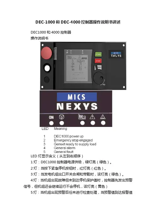
DEC-1000和DEC-4000控制器操作说明书讲述DEC1000和4000控制器操作说明书LED 灯显示含义(从左到右顺序)1灯:DEC1000控制器电源供给,绿灯亮(绿色)。
2灯:当按下紧急停机按钮时,红灯亮(红色)。
3灯:当发电机组出口开关合闸和带载时,该灯亮(绿色)。
4灯:当机组出现故障但未到达停机保护值时,控制器先发出预警信号,但机组还会继续运行不会停机,该灯亮(黄色)5灯:当机组出现预警后任未进行检查处理,当预警值到达报警值时,机组立即自动停止运行进行保护,该灯亮(红色)当机组运行时,RPM:显示机组运转的速度(1500转/分);同时显示机组运行时,充电机输出电压值:13.6V(直流)。
显示:控制器运行累计时间:23589小时;显示:发电机组输出电源频率:50Hz;显示:电池电压13.6V显示:柴油量在油箱的百分比值:37%显示:冷却液温度:85℃(水温)显示:机组运行中机油压力:3.2BAR以上为公制单位显示:柴油量在油箱的百分比值:37%显示:冷却液温度:85F(水温)显示:机组运行中机油压力:40-60PSI以上为英制单位显示:L1-L2相电压:404V;显示:L2-L3相电压:403V;显示:L3-L1相电压:401V显示:L1-N线电压233V;显示:L2-N线电压233V;显示:L3-N线电压232V.显示:L1相电流530A显示:L2相电流537A显示:L3线电流548A机侧启动1、将控制器上钥匙开关从左侧向右侧旋转,打开控制器电源,控制指示灯亮及液晶屏出现文字显示,控制器并读取程序;2、控制器绿色灯亮,说明机组无故障,准备就绪;3、按下“START”绿色按钮,机组立即进行预热10秒,10秒后机组立即启动,机组启动成功允许;4、读取机组允许参数:按下“左侧白色按钮”,每按一次,显示一组参数,其中参数包括:发动机转速、水温、机油压力、3相电压及频率、3相电流、电池电压等;5、按下“STOP”按钮,机组立即停止运转。
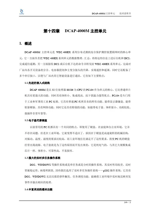
第十四章DCAP-4000M主控单元1.概述DCAP-4000M主控单元是WDZ-400EX系列分布式微机综合保护测控装置联网时的核心单元,它一方面负责把WDZ-400EX系列单元的数据整理、汇总,再将这些信息上送后台机和DCS,完成遥信遥测;另一方面接收DCS或后台机下达的命令并转发给WDZ-400EX系列单元,完成对厂站内各开关设备的分合、电容器投切和主变分接头的升降,实现遥控和遥调。
同时它还配备了多个串行接口,以便与厂站内其它智能设备进行通讯。
它有如下主要特点:1.1.先进的嵌入式结构DCAP-4000M是以32位处理器80586为CPU的PC104作为单元的核心,它比普通单片机具有更强大的功能,同时具有体积小、集成度高、抗干扰能力强等优点。
PC104是专门用于工业和军事的工业PC标准,它具有普通PC机所具有的所有功能、能带显示器键盘、能带软驱硬驱、具有网络功能,同时它还具有特别的功能,如能带电子盘、体积很小、功耗较低、接插件非常牢靠等。
1.2.电子盘代替硬盘以前常用的PC机都具有一个共同的特点,即使用了硬盘,在家庭和办公室环境,它并不存在问题,但是在工业环境,它就变得不适应了,原因在于硬盘是高速旋转的机械结构,对振动、温度、湿度的要求比较高,而工业环境往往满足不了这些要求,致使PC机的硬盘经常出现故障。
电子盘就是为了这些原因而开发出来的,它是纯电气的,与其它大规模集成芯片一样,体积小,可靠性高,不易损坏。
1.3.强大的实时多任务操作系统DOS、WINDOWS等操作系统或是单任务或是分时的操作系统,其实时性均较差,还时常被稳定性、病毒所困扰,因些我们选用了实时多任务操作系统—-pSOS操作系统,它具有DOS、WINDOWS无法比拟的事件触发、任务调度功能,能确保工业环境中实时地反映突发事件并做出相应的处理。
1.4.丰富灵活的通讯功能单元共有12个RS232/422/485接口,其中两个提供光纤接口。

960H TVL720u Ultra high resolution 960H (1/3“) DS sensoru True Wide Dynamic Range (WDR)u Digital noise reductionu Easy installation with 3-axis adjustmentu15 programmable privacy zonesThese Wide Dynamic Range (WDR) outdoor domes arecompact, stylish surveillance cameras that offerexcellent resolution in variable lighting conditions. Thehigh performance 960H 1/3‑inch Double Scan (DS)CCD sensor provides a resolution of 720TVL. The WDRfunction ensures the best image performance underdifficult (high contrast) lighting conditions. The waterresistant (IP66 rated) and vandal resistant (IK8 rated)housing ensures reliable video surveillance in a varietyof indoor and outdoor applications. The Day/Nightfeature ensures the highest image quality possible atany time by automatically switching from color tomonochrome. The camera is easy to install and can beadjusted around 3 axes.Certifications and approvalsApprobation standardsEnvironmental standardsTechnical specificationsFLEXIDOME AN outdoor 4000 WDR960H analog outdoor WDR dome camera. IP66; IK08; 12VDC/24VAC; varifocal 2.8 to 10.5 mm lens; true day/ night; 720 TVL; 3-axis adjustment; 4-zone motion detect; 15-zone privacy mask; NTSCOrder number VDN-244V03-2FLEXIDOME AN outdoor 4000 WDR960H analog outdoor WDR dome camera. IP66; IK08; 12VDC/24VAC; varifocal 2.8 to 10.5 mm lens; true day/ night; 720 TVL; 3-axis adjustment; 4-zone motion detect; 15-zone privacy mask; PALOrder number VDN-244V03-1FLEXIDOME AN outdoor 4000 WDR960H analog outdoor WDR dome camera. IP66; IK08; 12VDC/24VAC; varifocal 2.8 to 10.5 mm lens; true day/ night; 720 TVL; 3-axis adjustment; 4-zone motion detect; 15-zone privacy mask; NTSC; heaterOrder number VDN-244V03-2HFLEXIDOME AN outdoor 4000 WDR960H analog outdoor WDR dome camera. IP66; IK08; 12VDC/24VAC; varifocal 2.8 to 10.5 mm lens; true day/ night; 720 TVL; 3-axis adjustment; 4-zone motion detect; 15-zone privacy mask; PAL; heaterOrder number VDN-244V03-1HFLEXIDOME AN outdoor 4000 WDR960H analog outdoor WDR dome camera. IP66; IK08; 12VDC/24VAC; varifocal 2.8 to 10.5 mm lens; true day/ night; 720 TVL; 3-axis adjustment; 4-zone motion detect; 15-zone privacy mask; PAL; Chinese plug Order number VDN-244V03-1CAccessoriesVDA-WMT-AIDOME Indoor Wall MountIndoor wall mountOrder number VDA-WMT-AIDOMEVDA-PMT-AIDOME Indoor Pipe MountIndoor pipe mountOrder number VDA-PMT-AIDOMEVDA-WMT-AODOME Outdoor Wall MountOutdoor wall mountOrder number VDA-WMT-AODOMEVDA-PMT-AODOME Outdoor Pipe MountOutdoor pipe mountOrder number VDA-PMT-AODOMELTC 9213/01 Pole Mount AdapterFlexible pole mount adapter for camera mounts. Max.9 kg (20 lb); 3 to 15 inch diameter pole; stainless steel strapsOrder number LTC 9213/01Represented by:Americas:Europe, Middle East, Africa:Asia-Pacific:China:America Latina:Bosch Security Systems, Inc. 130 Perinton Parkway Fairport, New York, 14450, USA Phone: +1 800 289 0096 Fax: +1 585 223 9180***********************.com Bosch Security Systems B.V.P.O. Box 800025617 BA Eindhoven, The NetherlandsPhone: + 31 40 2577 284Fax: +31 40 2577 330******************************Robert Bosch (SEA) Pte Ltd, SecuritySystems11 Bishan Street 21Singapore 573943Phone: +65 6571 2808Fax: +65 6571 2699*****************************Bosch (Shanghai) Security Systems Ltd.201 Building, No. 333 Fuquan RoadNorth IBPChangning District, Shanghai200335 ChinaPhone +86 21 22181111Fax: +86 21 22182398Robert Bosch Ltda Security Systems DivisionVia Anhanguera, Km 98CEP 13065-900Campinas, Sao Paulo, BrazilPhone: +55 19 2103 2860Fax: +55 19 2103 2862*****************************© Bosch Security Systems 2014 | Data subject to change without notice 8318606475 | en, V12, 04. Jun 2014。
s lLeer atentamente antes de utilizar la máquina.Registre su producto y obtenga asistencia en/welcomeMáquina de café exprés superautomática4000 series INSTRUCCIONES DE USO HD8844E S05053Ajuste de la salida de café (27)Ajuste de la cantidad de café en taza (28)SUMINISTRO DE CAFÉ EXPRÉS Y CAFÉ EXPRÉS LARGO (29)Suministro de café exprés y café exprés largo con café en grano (29)Suministro de café exprés y café exprés largo con café premolido (30)SUMINISTRO DE CAFÉ LARGO (CLASSIC COFFEE) (31)Suministro de café largo (Classic Coff ee) con café en grano (31)Suministro de café largo (Classic Coff ee) con café premolido (32)CÓMO ESPUMAR LECHE Y PREPARAR UN CAPUCHINO (34)Cómo espumar leche (34)Cómo preparar un capuchino (37)SUMINISTRO DE AGUA CALIENTE (37)LIMPIEZA Y MANTENIMIENTO (39)Limpieza diaria de la máquina (39)Limpieza semanal de la máquina (41)Limpieza del depósito de agua (41)Limpieza diaria del Montador de leche Automático (42)Limpieza mensual del Montador de leche Automático (43)Limpieza semanal del grupo de café (49)Lubricación mensual del grupo de café (52)Limpieza mensual del grupo de café con pastillas desengrasantes (54)Limpieza mensual del contenedor de café en grano (56)DESCALCIFICACIÓN (57)Fase de preparación (57)Fase de descalcifi cación (59)Fase de enjuague (60)Interrupción del ciclo de descalcifi cación (63)PROGRAMACIÓN (64)Parámetros que pueden ajustarse (64)Cómo programar la máquina (65)SIGNIFICADO DE LOS SÍMBOLOS DE LA PANTALLA (67)RESOLUCIÓN DE PROBLEMAS (71)AHORRO ENERGÉTICO (75)Stand-by (75)CARACTERÍSTICAS TÉCNICAS (75)CONFIGURACIÓN DE FÁBRICA (76)GARANTÍA Y ASISTENCIA (76)Garantía (76)Asistencia (76)PEDIDO DE PRODUCTOS PARA EL MANTENIMIENTO (77)4ESPAÑOLESPAÑOL5• No tocar las superfi cies calientes. Usar los asideros y man-dos correspondientes.• Apagar la máquina por medio del interruptor general situa-do en la parte trasera y desconectar el enchufe de la toma: - si se producen anomalías;- si la máquina no va a utilizarse durante un largo perío-do;- antes de proceder a la limpieza de la máquina.• Tirar del enchufe y no del cable de alimentación.• No tocar el enchufe con las manos mojadas.• No utilizar la máquina si el enchufe, el cable de alimenta-ción o la propia máquina han sufrido daños.• No alterar ni modifi car de ninguna forma la máquina o el cable de alimentación. Para evitar riesgos, todas las repa-raciones deberán ser efectuadas por un centro de asistencia técnica autorizado por Philips.• La máquina no está destinada a ser utilizada por niños de edad inferior a 8 años.• La máquina puede ser utilizada por niños de 8 años de edad (y superior) siempre que previamente hayan sido instruidos en el correcto uso de la máquina y sean conscientes de los peligros asociados o la utilicen bajo la supervisión de un adulto.• La limpieza y el mantenimiento no deben ser llevados a cabo por niños salvo que tengan más de 8 años y estén su-pervisados por un adulto.• Mantener la máquina y su cable de alimentación lejos del alcance de los menores de 8 años.• La máquina puede ser utilizada por personas con capaci-dades físicas, mentales o sensoriales reducidas o que no dispongan de una sufi ciente experiencia y/o competencias siempre que previamente hayan sido instruidas en el co-rrecto uso de la máquina y sean conscientes de los peligros6ESPAÑOLESPAÑOL710ESPAÑOL. Pulsar elEn caso de necesidad, puede interrumpirse el ciclo por medio del botón “”.8 La máquina visualiza la pantalla adyacente y está lista para el suminis-tro.5 Pulsar el botón “” para aumentar el valor y el botón “” para dismi-nuirlo.6 Pulsar el botón “” para confi rmar la confi guración.7 Pulsar el botón “” para salir del MENÚ de programación.4 Introducir el fi ltro de agua “INTENZA+” en el depósito de agua vacío. Empujarlo hasta el punto más bajo posible.5 Llenar el depósito de agua con agua fresca y volver a introducirlo en la máquina.6 Suministrar toda el agua contenida en el depósito mediante la función de agua caliente (ver capítulo “Suministro de agua caliente”).7 Volver a llenar el depósito de agua.8 Pulsar el botón “” y pasar las opciones pulsando el botón “” hasta que se visualice la pantalla adyacente.9 Pulsar el botón “” para entrar en la función.10 Pulsar el botón “” para seleccionar “ON” y, a continuación, pulsar el botón “” para confi rmar.11 Para salir, pulsar el botón “”.12 La máquina visualiza la pantalla adyacente y está lista para el suminis-tro.Tras estos pasos, la máquina ya está programada para informarle de cuán-do debe sustituir el fi ltro de agua “INTENZA+”.. botón “” o un café exprés largo pulsando el botón “”..En esta posición se puede suministrar un café largo (Classic Coff ee) pulsando el botón “”.ee) con la palanca situada en lagurado. Es posible confi gurar 5(), para un molido grueso(), para un molido fi no y un saborcar la confi-Es posible salir de la programación pulsando el botón “como se muestre “”Se puede memorizar la cantidad del producto desde el instante en queaparezca el símbolo “2 Pulsar el botón “” para seleccionar la función de café premolido.3 Levantar la tapa del compartimento correspondiente y añadir unacucharada rasa de café premolido. Utilizar únicamente la cuchara do-sifi cadora suministrada con la máquina. A continuación, cerrar la tapa del compartimento de café premolido.Atención:Verter sólo café premolido en el compartimento de café premolido. La introducción de otras sustancias u objetos puede causar graves daños a la máquina. Dichos daños no estarán cubiertos por la garantía.4 Pulsar el botón “” para un café largo (Classic Coff ee). Se activará elciclo de suministro.5 El suministro de café se detiene automáticamente al alcanzarse el nivelprogramado; para interrumpirlo con antelación, pulsar el botón “”. Una vez fi nalizado el suministro, la máquina vuelve al menú principal. Para suministrar otros cafés con café premolido, repetir las operaciones que se acaban de describir.Nota:En caso de no haber introducido café premolido en el compartimento de café premolido, sólo se suministrará agua.Si se añade más de una cucharada, la máquina no suministrará el productoy el café molido se descargará en el cajón de recogida de posos.cie exterior delPulsar el botón “” para detener el suministro.El suministro de leche espumada se interrumpe tras 3 minutos. Pulsar el botón “” para un nuevo suministro.gura.Pulsar el botón “” para comenzar a espumar la leche.2 Colocar un recipiente bajo el tubo de vapor.6 La máquina necesita un tiempo de precalentamiento; durante esta fase se visualiza el símbolo adyacente.7 Suministrar la cantidad de agua caliente deseada. Para interrumpir el suministro de agua caliente, pulsar el botón “”.3 Pulsar el botón “”; la pantalla mostrará el símbolo adyacente.4 Pulsar el botón “”; la pantalla mostrará el símbolo adyacente.5 Pulsar el botón “” para poner en marcha el suministro de agua calien-te.124 Volver a colocar el cajón de recogida de posos en la bandeja de goteoe introducirla en la máquina.Nota:Vaciar la bandeja de goteo también cuando el indicador de bandeja de goteo llena se eleve.Nota:Si estas acciones se llevan a cabo con la máquina apagada, al volver a encenderla seguirá apareciendo la alarma adyacente.Nota:El resto de operaciones de mantenimiento deben efectuarse únicamente con la máquina apagada y desconectada de la red eléctrica.7 Durante el suministro se visualiza el símbolo adyacente. Una vez que sehaya suministrado toda la solución, pulsar el botón “” para detener el suministro.Atención:No beber la solución suministrada durante este proceso.8 Enjuagar bien el recipiente y llenarlo con ½ l de agua fresca, que seráutilizada para el ciclo de enjuague.9 Introducir el tubo de aspiración en el recipiente.10 Vaciar el recipiente y volver a colocarlo bajo el Montador de lecheAutomático.11 Pulsar el botón “” para suministrar vapor.12 La máquina necesita un tiempo de precalentamiento; durante esta fasese visualiza el símbolo adyacente.se haya suministrado toda el agua, pulsar el botón “” para detener elgura.gura.123ltro superior.。

XY1000-3000火灾报警系列产品JB-QB-XY1000-3000火灾报警控制器(联动型)使用说明书大连欣洋电子消防设备有限公司二OO三年九月1概述1.1 JB-QB-XY1000-3000火灾报警控制器(联动型)是根据国家最新联动标准GB16806-1997《消防联动控制设备通用技术条件》和GB4717-93《火灾报警控制器通用技术条件》研制开发的新一代高科技产品。
控制器采用MCS-51系列单片机CPU及外围芯片构成。
该控制器所挂接各种探测器、模块等设备均采用P87LPC76X系列单片机控制,并采用无极性二总线方式从而构成科学的、先进的分布智能式火灾报警系统。
1.2 该控制器采用大屏幕全汉字液晶显示,并挂有了国家标准二级字库,使各种警情的提示信息详尽准确。
融合了当今广泛普及的计算机与手机中大家都熟悉的操作方式,使日常操作,维护变得简单、容易,相信会使用户感到方便。
1.3本机具有强大而操作又很简单的现场编程功能,能够满足各种复杂的逻辑关系要求,达到报警时准确、可靠地启动现场设备;科学合理地达到灭火的要求。
1.4该控制器必须同本公司生产的外部设备配合,组成火灾报警控制系统。
另外该控制器的壁挂型还设8 组多线直接输出接点。
可直接启停消防泵等重要外部设备。
1.5本机采用金属喷塑外壳;面板采用丝印技术工艺;轻触式按键;超高亮的指示灯;动态液晶显示画面;超强功能,高可靠的稳定性,相信会赢得用户的信赖和满意。
2 基本原理及主要特点2.1 基本原理火灾报警控制器的主要功能是准确地向人们报告火灾信息,这是众所周知的道理,那么如何能让火灾报警控制器报警准确,也就是尽可能减少误报警,这一直是从事火灾报警研究人员的研究课题。
模拟量火灾报警系统虽然在一定程度上减少了系统的误报率,但还是没有将系统设计为最佳,因此人们还是一直在寻求更佳的设计方案。
九十年代后期,微型单片机技术的发展给智能化设计带来了革命,很多领域均开始应用智能化设计产品。
警告 (1)一.简介 (2)二.电气符号 (2)三.技术规格 (2)1.基准条件和工作条件 (2)2.一般规格 (3)3.基准条件下基本误差及性能指标 (4)四.仪表结构 (4)五.操作方法 (5)1.开关机 (5)2.数据保持/取消 (5)3.背光灯控制 (5)4.相位测量 (5)5.交流电流、漏电流测量 (6)6.交流电压测量 (6)7.感性、容性电路判别 (6)8.三相电压相序测量 (7)六.电池更换 (7)七.其他说明及注意事项 (8)八.配置清单 (9)附:测试接线参考图 (9)感谢您购买了本公司的VICTOR4000双钳数字相位伏安表,为了更好地使用本产品,请一定:——详细阅读本用户手册。
——严格遵守本手册所列出的安全规则及注意事项。
.任何情况下,使用本仪表应特别注意安全。
.注意本仪表面板及背板的标贴文字及符号。
.使用前应确认仪表及附件完好,仪表、测试线绝缘层无破损、裸露及断线才能使用。
.测试前请先确认功能开关已设定在适当的量程范围内。
.不能用于测试高于 500V的电压。
.仪表后盖及电池盖板没有盖好禁止使用。
.确定导线的连接插头已紧密地插入接口内。
.仪表于潮湿状态下,请勿使用,或更换电池。
.禁止在易燃性及危险场所测试。
.测试线必须撤离被测导线后才能从仪表上拔出,不能手触输入插孔,以免触电。
.请勿在强电磁环境下使用,以避免影响仪器正常工作。
.仪表在使用中,机壳或测试线发生断裂而造成金属外露时,请停止使用。
.请勿于高温潮湿,有结露的场所及日光直射下长时间放置和存放仪表。
.仪表及电流钳口必须定期保养,保持清洁,不能用腐蚀剂和粗糙物擦拭钳口。
.避免电流钳受冲击,尤其是钳口接合面。
.仪表具有自动关机功能。
.长时间不用本仪表,请取出电池,更换电池请注意电池极性。
注意本仪表所规定的测量范围及使用环境。
.使用、拆卸、校准、维修本仪表,必须由有授权资格的人员操作。
.由于本仪表原因,继续使用会带来危险时,应立即停止使用,并马上封存,由有授权资格的机构处理。
WD Sentinel DX4000小型办公存储服务器一、产品特点即插即用简便的安装过程可以让您像专业人士一样将WD Sentinel 整合到办公网络中。
管理控制面板可以快速引导您完成添加用户、设置用户访问权限、创建共享文件夹以及制订备份计划。
易于管理设备正面的液晶显示屏可以让您监控系统状态和关键警报。
维护工作量降到了最低,通过控制面板可以完全查看系统的运行状况。
拥有成本低WD Sentinel 为您的小型办公环境提供经济实惠的数据保护方案。
它内置了最多可为网络中25 台客户端计算机提供保护的软件;与同类其他产品不同,它不需要为每一台额外的计算机购买额外的备份软件许可证。
全方位的数字保护WD Sentinel 为小型办公网络提供全方位的数据保护,它配有WD 的企业级WD RE 硬盘、1 或5 级RAID、自动备份与还原、双重千兆位以太网端口、可选的备份电源以及可选的异地灾难恢复服务。
用户可自行维护要更换或添加硬盘,只要打开柜门,更换好硬盘,WD Sentinel 就会完成剩下来的事。
它会无缝地将服务器迁移到相应的RAID 级别,并自动扩展服务器的存储容量,不需要停机。
随着业务的增长,不需要任何专业技术知识,您自己就能扩大存储容量。
与行业领导者合作WD Sentinel 集成了行业领导者的软硬件。
它采用了WD 的企业级RAID 硬盘以及Intel Atom 双核处理器,并安装了Windows? Storage Server 2008R2 Essentials 软件,为小型办公环境提供一个可靠、安全和易于管理的存储服务器。
先进性能超快的千兆位以太网接口提供最高85 MB/s 的读写速度,比典型的NAS解决方案的三倍速度还快*。
*普通NAS 解决方案的读写性能为30 MB/s。
安全远程访问内置的安全远程访问功能可以让员工、客户或供应商从任何连接互联网的计算机访问WD Sentinel 中的文件。
内置DLNA 媒体服务器内置的DLNA 媒体服务器可通过办公网络或互联网流式传输共享媒体库和数字广告。
4000 lb. Adjustable Gantry CraneOwner’s ManualWARNING: Read carefully and understand all ASSEMBLY AND OPERATION INSTRUCTIONS before operating. Failure to follow the safety rules and other basic safety precautions may result in serious personal injury.Item #52523Thank you very much for choosing a Strongway™ product!For future reference, please complete the owner’s record below:Serial Number/Lot Date Code: ________________________________ Purchase Date: ____________________________________________ Save the receipt, warranty, and this manual. It is important that you read the entire manual to become familiar with this product before you begin using it.This Gantry Crane is designed for certain applications only. Northern Tool and Equipment is not responsible for issues arising from modification or improper use of this product such as an application for which it was not designed. We strongly recommend that this product not be modified and/or used for any application other than that for which it was designed.For technical questions, please call 1-800-222-5381.Intended Use (4)Technical Specifications (4)Important Safety Information (4)Safety Labels (6)Assembly Instructions (6)Operating Instructions (8)Maintenance (9)Parts Diagram (10)Parts List (11)Replacement Parts (11)Limited Warranty (12)The Gantry Crane is ideal for shops where heavy level lifting is essential.Capacity: 2 TonAdjustable Height: 7’ 11” - 11’ 9”Casters: 5”Assemble the crane loosely until the entire assembly is complete. Make certain that you have a large, clean, and uncluttered area for assembly. As the crane is large and heavy, you may have to lay out the different parts on their sides, and tighten and erect the entire assembly once complete.Step 1) Attach two Plates (#20) from two sides to the one end of the Crossbeam (#19). Secure with the four Bolts (#1), Washers (#2), Spring Washers (#3), and Nuts (#4). Repeat for theother end.Step 2) Attach each Inner Vertical Post Assembly to the Crossbeam (#19). Secure with the 8 Bolts (#1), Washers (#2), Spring Washers (#3), and Nuts (#4)Step 3) Attach the four Swivel Casters with Brake (#27) to the Base Assembly (#26). Apply grease to the zerk in each Caster.Step 4) Attach each Outer Vertical Post Assembly (#24) to each Base Assembly (#26), making certain that the slot at two sides of the Outer Vertical Post Assembly are facing theCasters’ direction. From the top, insert two (2) Bolts (#14) through the base of the OuterVertical Post Assembly, and into the Base Assembly (#26). Slip on the Washer (#2) andSpring Washer (#3) and secure by tightening the Nuts (#4).Step 5) Attach two Support Tubes (#22) to each Outer Vertical Post Assembly (#23). Insert the Bolt (#5) through the top of the Support Tube, and through the Eyelet. Slip on a Washer(#6) and Spring Washer (#7) and secure with the Nut (#8). Attach the other end of theSupport Tube to the Base Assembly with Bolts, Washers, Spring Washers, and Nuts.Repeat for all four Support Tubes.Step 6) Insert the Inner Vertical Post (#21) into the Outer Vertical Post (#23). Insert one (1) Pin of the Pins with Chain (part #18) through the slot and the Inner Vertical Post Hole so that itgoes all the way through to the other pin. Attach the Handle (#24) to the bracket on theside of Outer Vertical Post, insert the Bolt (#10) from the inside, slip on the Washer (#14)and Spring Washer (#15) and secure with the Nut (#11). Make sure the two (2) hooks ofthe Handle hold the two ends of the Pin (#18). Repeat for the other Post Assembly.Step 7) Tighten all the Bolts and Nuts securely and make certain that the entire assembly is tight and secure.Step 8) Test the crane according to manual and ANSI/ASME B30.17 standards.Step 1) Move the crane so that it is directly above the item to be lifted.Step 2) Securely fasten the item to the crane with the appropriate trolley or hoist.Step 3) Raising and lowering the Crossbeam requires two people. There is a Handle (#27) on each of the Outer Vertical Post Assemblies. To raise the Crossbeam, press the handle and theInner Vertical Post will be up by one hole, insert the other Pin into this hole to hold theposition. Pull out the original pin and hook the handle to the new positioned pin. Repeat toreach the height you need. The Inner Vertical Post Assembly has thirteen different stopping positions.# 52523 -2T∙For replacement parts and technical questions, please call Customer Service at 1-800-222-5381. ∙Not all product components are available for replacement. The illustrations provided are a convenient reference to the location and position of parts in the assembly sequence.∙When ordering parts, the following information will be required: item description, item model number, item serial number/item lot date code, and the replacement part reference number.∙The distributor reserves the rights to make design changes and or improvements to product lines and manuals without notice.Northern Tool and Equipment Company, Inc. ("We'' or '"Us'') warrants to the original purchaser only ("You'' or “Your”) that the Strongway product purchased will be free from material defects in both materials and workmanship, normal wear and tear excepted, for a period of one year from date of purchase. The foregoing warranty is valid only if the installation and use of the product is strictly in accordance with product instructions. There are no other warranties, express or implied, including the warranty of merchantability or fitness for a particular purpose. If the product does not comply with this limited warranty, Your sole and exclusive remedy is that We will, at our sole option and within a commercially reasonable time, either replace the product or product component without charge to You or refund the purchase price (less shipping). This limited warranty is not transferable.Limitations on the WarrantyThis limited warranty does not cover: (a) normal wear and tear; (b) damage through abuse, neglect, misuse, or as a result of any accident or in any other manner; (c) damage from misapplication, overloading, or improper installation; (d) improper maintenance and repair; and (e) product alteration in any manner by anyone other than Us, with the sole exception of alterations made pursuant to product instructions and in a workmanlike manner.Obligations of PurchaserYou must retain Your product purchase receipt to verify date of purchase and that You are the original purchaser. To make a warranty claim, contact Us at 1-800-222-5381, identify the product by make and model number, and follow the claim instructions that will be provided. The product and the purchase receipt must be provided to Us in order to process Your warranty claim. Any returned product that is replaced or refunded by Us becomes our property. You will be responsible for return shipping costs or costs related to Your return visit to a retail store.Remedy LimitsProduct replacement or a refund of the purchase price is Your sole remedy under this limited warranty or any other warranty related to the product. We shall not be liable for: service or labor charges or damage to Your property incurred in removing or replacing the product; any damages, including, without limitation, damages to tangible personal property or personal injury, related to Your improper use, installation, or maintenance of the product or product component; or any indirect, incidental or consequential damages of any kind for any reason.Assumption of RiskYou acknowledge and agree that any use of the product for any purpose other than the specifieduse(s) stated in the product instructions is at Your own risk.Governing LawThis limited warranty gives You specific legal rights, and You also may have other rights which vary from state to state. Some states do not allow limitations or exclusions on implied warranties or incidental or consequential damages, so the above limitations may not apply to You. This limited warranty is governed by the laws of the State of Minnesota, without regard to rules pertaining to conflicts of law. The state courts located in Dakota County, Minnesota shall have exclusive jurisdiction for any disputes relating to this warranty.Distributed by:Northern Tool & Equipment Company, Inc.Burnsville, Minnesota 55306Made in China。
1A . 工业电气系统B . 控制系统C . 大型工业设备D . 重型机械E . 任何交流接地系统 1. 接线端子说明:A1:控制电源L 或DC+的输入端 A2:控制电源N 或DC-的输入端 GND :接地端N01、NO2:继电器报警常开输点 NC1、NC2:继电器报警常闭触点 CT1、CT2:电流传感器二次侧接入端 R1、R2 :复位功能外部输入VA 、V-、V+:模拟量输出,V+与V-为4~20mA 输出,VA 与V-为0~5V 输出,线性对应的漏电流值为0~设定值或0~5A 。
CG 、C+、C-:通讯功能输出接口,为选配功能。
2. LED 指示灯说明:RUN : 绿色LED 指示,闪烁则表示设备正常运行。
CT : 红色LED 指示,亮则表示CT 回路开路。
TRIP : 红色LED 指示,亮则表示漏电流值已达到电流设置值且超过设置的时间。
RXD : 绿色LED 指示,灯闪烁则表示装置在接受数据。
TXD : 绿色LED 指示,灯闪烁则表示装置在发送数据。
1. 适用于交流直接接地系统和电阻接地系统。
2. 提供灵敏的接地接地故障,有效防止误跳闸。
3. 电流互感器(CT )开路监控。
4. 从10mA 到5A 可调跳闸设置。
5. 一组独立的继电器报警输出。
6. 一组模拟量变送输出。
7. 多类型、宽范围控制电源输入。
8. 人性化简易操作界面。
9.DIN 导轨和螺钉两种安装方式。
23. 旋转拨码开关设置: LEVEL (mA ):箭头指向的值对应继电器的动作值,当系统监测到的漏电流值大于该设置值且达到TIME 设置的时间,那么继电器动作。
TIME (mA ):箭头指向的值对应的是漏电流采样时间,当系统监测到的漏电流值大于该设置值且达到TIME设置的时间,那么继电器动作。
4.DIP 拨码开关设置:掀开装置侧面的橡皮塞,会看到8位的DIP 拨码开关说明:模拟量输出:A 、对应0~设定这值,即模拟量输出,如4~20mA 或0-5V 对应的值是0~设定脱扣电平值。
4000 seriesSuper automatic espresso machineEN USER MANUALDE BENUTZERHANDBUCH ES MANUAL DEL USUARIO FR MODE D’EMPLOI IT MANUALE UTENTENL GEBRUIKSAANWIJ ZINGEP4051, EP40504219.460.3761.1 PHILIPS4000 OTC_FRONT-BACK_A5_WE.indd 122-11-16 10:464EnglishContentsMachine overview_________________________________________________________________5 Introduction ______________________________________________________________________5 First installation___________________________________________________________________6 AquaClean filter __________________________________________________________________6 Activating the AquaClean filter_______________________________________________________6 Replacing the AquaClean filter_______________________________________________________7 Replacing the AquaClean filter after 8 filters were used__________________________________8 Measuring the water hardness_______________________________________________________8 Control panel and display___________________________________________________________9 One-touch beverage buttons________________________________________________________9 Navigation buttons________________________________________________________________9 MENU button ____________________________________________________________________9 AROMA STRENGTH button _________________________________________________________10 CoffeeSwitch_____________________________________________________________________10 Brewing coffee____________________________________________________________________10 Brewing coffee with beans__________________________________________________________10 Brewing coffee with pre-ground coffee________________________________________________11 Other drinks and hot water__________________________________________________________11 Special drinks and hot water_________________________________________________________11 How to select other drinks__________________________________________________________11 Dispensing hot water_______________________________________________________________11 Brewing milk-based coffee beverages and milk froth____________________________________12 Adjusting volume and taste_________________________________________________________12 Adjusting coffee and milk volume____________________________________________________12 Adjusting coffee strength___________________________________________________________13 Adjusting grinder settings___________________________________________________________13 Cleaning and maintenance__________________________________________________________14 Cleaning table ____________________________________________________________________14 Cleaning the brew group____________________________________________________________15 Cleaning the brew group under the tap________________________________________________15 Cleaning the brew group with coffee oil remover tablets__________________________________15 Reinserting the brew group__________________________________________________________16 Lubrication_______________________________________________________________________17 Cleaning the milk carafe ____________________________________________________________17 Carafe quick clean_________________________________________________________________17 Thorough cleaning of the milk carafe__________________________________________________18 Weekly cleaning of the milk carafe___________________________________________________18 Disassembling the milk dispensing spout______________________________________________18 Reassembling the milk carafe________________________________________________________19 Monthly cleaning of the milk carafe___________________________________________________19 Descaling procedure_______________________________________________________________20 What to do if the descaling procedure is interrupted_____________________________________22 Warning icons and error codes_______________________________________________________22 Meaning of the warning icons________________________________________________________22 Meaning of the error codes__________________________________________________________23 Troubleshooting___________________________________________________________________24Machine overview1User interface (EP4050 only)12Drip tray release button 1A ESPRESSO button 13Cord1B CAPPUCCINO button 14Grind setting knob 1C LATTE MACCHIATO button 15Cover of bean hopper 1D Standby button16Bean hopper 1E CLASSIC COFFEE button 17Brew group1F AROMA STRENGTH button 18Inside of service door with contact information 1G MENU button19Coffee exit duct 2User interface (EP4051 only)20Coffee residues drawer 2A ESPRESSO button 21Coffee grounds container 2B CAPPUCCINO button 22Drip tray cover2C AROMA STRENGTH button 23Hot water dispensing spout2D Standby button24Opening for hot water dispensing spout 2E CLASSIC COFFEE button 25CoffeeSwitch 2F CAFÉ AU LAIT button 26Water tank 2G MENU button27AquaClean filter 3Adjustable coffee dispensing spout 28Milk container 4Lid of water tank 29Milk dispensing unit 5Lid of bean hopper30Lid of milk dispensing unit 6Lid of pre-ground coffee compartment 31Milk dispensing spout7Main switch 32Grease tube with application tip and cap 8Socket for cord 33Cleaning brush 9Service door34Measuring scoop 10'Drip tray full' indicator 35Water hardness test strip11Drip trayIntroductionCongratulations on your purchase of a Philips full-automatic coffeemachine! To fully benefit from the support that Philips offers, please register your product at /coffee-care .Read the separate safety booklet carefully before you use the machine for the first time and save it for future reference.5EnglishError code Problem Cause Possible solutionThe AquaClean filter was not prepared well before installation.Switch off the machine and remove the filter from the water tank. Immerse the filter upside down in a jug with cold water and wait until no more air bubbles come out. Place back the filter in the water tank, restart the machine and dispense 2-3 cups of hot water.14The machine isoverheated. This can have severalcauses.Switch the machine off and switch itback on again after 30 minutes.TroubleshootingThis chapter summarizes the most common problems you could encounterwith the machine. Support videos and a complete list of frequently askedquestions are available on /coffee-care. If you are unableto solve the problem, contact the Consumer Care Center in your country. Forcontact details, see the warranty leaflet.Problem Cause SolutionThe machine does not switch on.The machine is disconnected orthe main switch is in the 'off'position (0).Check if the mains cord is insertedcorrectly.Make sure the main switch is set to 'on'position (I).The machine is in DEMO mode.You pressed the standby buttonfor more than 8 seconds.Switch the machine off and then onagain with the main switch on the backof the machine.The drip tray fills up quickly.This is normal. The machineuses water to rinse the internalcircuit and brew group. Somewater flows through the internalsystem directly into the driptray.Empty the drip tray when the 'drip trayfull' indicator pops up through the driptray cover. Place a cup under thedispensing spout to collect rinsing water.The 'coffee grounds container full' icon remains displayed. You emptied the coffee groundscontainer while the machinewas switched off.Always empty the coffee groundscontainer while the machine is switchedon. If you empty the coffee groundscontainer when the machine is switchedoff, the coffee cycle counter is not reset. You placed back the coffeegrounds container too fast.Do not place back the coffee groundscontainer until the display messageprompts you to put it back.I cannot remove the brew group.The brew group is not in thecorrect position.Close the service door. Switch themachine off and back on again. Wait forthe 'machine ready' screen to appearand then remove the brew group.24EnglishProblem Cause SolutionYou have not removed the coffee grounds container.Remove the coffee grounds container before you remove the brew group.I cannot insert the brew group.The brew group is not in thecorrect position.Reset the machine in the following way:place the drip tray and the coffeegrounds container back. Leave the brewgroup out. Close the service door andswitch the machine on and off. Then putthe brew group in the correct position(see 'Reinserting the brew group') andreinsert it in the machine.The machine is still in thedescaling procedure.You cannot remove the brew groupwhen the descaling procedure is inprogress. First complete the descalingprocedure and then remove the brewgroup.The coffee is watery.The grinder is set to a toocoarse setting.Adjust the grinder to a finer setting.The coffee exit duct is clogged.Clean the coffee exit duct with thehandle of the measuring spoon or aspoon handle. Then switch theappliance off and on again.The machine is performing itsself-adjustment procedure.Brew a few cups of coffee.The brew group is dirty or needsto be lubricated.Clean and lubricate the brew group.Coffee is leaking from the coffee dispensing spout.The coffee dispensing spout isclogged.Clean the coffee dispensing spout andits holes with a pipe cleaner.The coffee exit duct is clogged.Clean the coffee exit duct with thehandle of the measuring spoon or aspoon handle. Then switch theappliance off and on again.The coffee is not hot enough.The cups you use are cold.Preheat the cups by rinsing them withhot water.The temperature is set too low.Check the menu settings.Set the temperature to 'high' in themenu.You added milk.Whether the milk you add is warm orcold, it always decreases thetemperature of the coffee to someextent.The machine does not grind the coffee beans.The coffee exit duct is clogged.Clean the coffee exit duct25EnglishProblem Cause SolutionThe machine grinds the coffee beans, but coffee does not come out or coffee comes out slowly.The coffee exit duct is blocked.Clean the coffee exit duct with thehandle of the measuring spoon or aspoon handle. Switch the appliance offand on again.The AquaClean filter was notprepared well for installation.Switch off the machine and remove thefilter from the water tank. Immerse thefilter upside down in a jug with coldwater and wait until no more air bubblescome out. Place back the filter in thewater tank, restart the machine anddispense 2-3 cups of hot water.The grinder is set to a too finesetting.Adjust the grinder to a coarser setting. The brew group is dirty.Clean the brew group.The coffee dispensing spout isdirty.Clean the coffee dispensing spout andits holes with a pipe cleaner.The machine circuit is blockedby limescale.Descale the machine.The milk does not froth.The milk carafe is dirty or notinserted correctly.Clean the carafe and make sure that you position and insert it correctly.The milk dispensing spout has not been opened fully.Make sure that the milk dispensing spout is in the correct position.The milk carafe is incompletely assembled.Make sure that all the components (especially the milk tube) have been assembled correctlyThe type of milk used is not suitable for frothing.Different types of milk result in different amounts of froth and different froth qualities. We have tested the following milk types which proved to deliver a good milk froth result: semi-skimmed or full-fat cow's milk, soy milk and lactose-free milk.There is water under the machine.The drip tray is too full and hasoverflowed.Empty the drip tray when the 'drip trayfull' indicator pops up through the driptray. Always empty the drip tray beforeyou start descaling the machine.The machine is not placed on ahorizontal surface.Place the machine on a horizontalsurface so that the 'drip tray full'indicator works properly.I cannot activate the AquaClean filter and the machine asks for descaling.You have already replaced theAquaClean filter 8 times.Descale your machine first and installthe AquaClean filter. Always activate theAquaClean filter in the menu (see'Activating the AquaClean filter'). Also dothis when you replace the filter.26EnglishProblem Cause SolutionThe filter has not been replaced in time after the AquaClean filter icon flashed and the capacity dropped to 0%. Descale your machine first and then install the AquaClean filter.You did not install the AquaClean filter during first installation, but after having brewed approx. 50 coffees (based on 100ml cups). The machine has to be completely limescale-free before you install the AquaClean filter.First descale the machine and then install a new AquaClean filter. After descaling, the filter counter is reset to 0/8. Always confirm filter activation in the machine menu. Also do this after filter replacement.You did not activate the new or replaced AquaClean filter in the machine menu.Descale your machine first. Then activate the AquaClean filter in the menu (see 'Activating the AquaClean filter'). Also do this when you replace the filter.The AquaClean filter icon does not appear on the display after I replaced the filter.You did not confirm activation inthe machine menu.Confirm the activation of the filter in themachine menu. (see 'Activating theAquaClean filter') If the display shows'START CALC CLEAN', you first need todescale the machine. Remove theAquaClean filter before descaling andreinsert it afterwards.The AquaClean filter is installed, but the descaling message appears.You have not activated theAquaClean filter in the machinemenu.First descale the machine and theninstall a new AquaClean filter. This willreset the filter counter to 0/8. Alwaysconfirm filter activation in the machinemenu (see 'Activating the AquaCleanfilter'), also after filter replacement.The new water filter does not fit.You are trying to install anotherfilter than the AquaClean filter.Only the AquaClean filter fits into themachine.27English。
WD-4000变频恒压供水电脑控制器使用手册目录系统概述 (2)主要性能指标 (2)安装尺寸和接线端子说明 (3)操作面板指示及参数设定说明 (4)参数列表及参数出厂默认值 (6)恢复系统参数出厂值 (6)系统参数功能详细说明 (9)故障显示代码说明 (16)外部输入信号端子说明 (16)系统当前时间的调整 (16)手动临时开机的调整 (16)外部输出端子与部分变频器端子的连接表 (17)控制器与压力变送器的连接 (18)RS485远程通讯接口 (18)1一、系统概述WD-4000系列微电脑变频供水/补水控制器是专为变频恒压供水系统和锅炉及换热系统补水而设计的电脑控制器,可与各种品牌的变频器配套使用。
具有压力控制精度高、压力稳定、第二消防压力(动压)设定、系统超压泄水自动控制、设定参数密码锁定等多项功能。
二、主要性能指标1.可编程设定多种泵工作方式,最多可拖4台泵循环启动;2.可选配的RS485远程通讯接口,标准组态软件支持远程通讯;3.参数调整和设定具有密码锁定及保护功能;4.采用人工智能模糊控制算法,设定参数少,控制精度高,内带看门狗电路,采用数字滤波及多项抗干扰措施,防止软件跑飞;5.可接无源远传压力表、有源电压及电流型压力变送器;6. D/A输出控制频率电压为DC 0-10V, 也可设定为DC 0-5V;7.具有压力传感器零点和满度补偿功能;8.具有定时自动倒泵功能;9.具有第二压力(消防压力)设定和控制功能;10.具有缺水自动检测保护功能和外部输入停机保护功能;11.系统补水控制时,具有超压自动泄水控制功能;12.具有供水附属小泵控制功能,可设定小泵变频或工频模式;13.具有可选的定时自动开、关机控制功能;14.具有小流量水泵睡眠控制功能;15.具有手操器功能,可手动调节输出电压来控制变频器的频率;16.可代替电接点压力表进行上、下限压力控制;17.具有分时分压供水控制功能,最多有六段时间控制;2三、安装尺寸和接线端子说明1.控制器外形尺寸: 160mm×80mm×90mm2.控制柜面板开口尺寸151mm×75mm,面板卡入式安装。
3.使用环境为:无水滴、蒸汽、腐蚀、易燃、灰尘及金属微粒的场所;4.使用环境温度:-20℃~50℃5.相对湿度:<95%;6.额定工作电压:AC220V±10%;7.控制器额定功耗:<=AC 5W;8.控制器接线端子输出容量:3A/ AC220V9.面板及接线端子说明:WD-4000型控制器面板示意图3WD-4000 型控制器端子接线图WD-4000型控制器接线端子说明:1------TX+ (RS485通讯接口+) 2------TX –(RS485通讯接口-)3------GND(信号地) 4------CM1(正转运行信号)5------FWD(正转运行信号) 6------ V+ (远传压力表高端+5V)7------IN(压力信号输入0-5V) 8------ GND(压力信号输入地)9------ DI2(缺水或停机信号输入) 10------DI1(第二压力信号输入端)11----- D/A (DC 0-10V输出) 12------ CM2(信号公共端2)13----- N(AC 220V零线) 14------L( AC 220V火线)15-----B1(1#变频运行触点) 16------B2(2#变频运行触点)17-----B3(3#变频运行触点) 18-----G1(1#工频运行触点)19-----G2(2#工频运行触点) 20-----G3(3#工频运行触点,泄压阀触点) 21-----B4(4#变频运行触点) 22-----G4(4#工频运行触点)23-----NC(空端子) 24-----NC(空端子)四、操作面板指示及参数设定说明面板及按键:PV窗口为测量值显示窗口,SV窗口为设定值显示窗口。
"S"键为参数4设定键,"▲"和"▼"为两个数字加减键,在参数设定状态,"M"键和""键为参数翻页键;在正常工作状态,""键为显示方式转换键,用来转换显示压力值和输出频率值;"●"键为工厂保留测试键.工作状态指示灯四个泵工作状态指示灯P1、P2、P3、P4表示四台泵,当指示灯为绿色时表示对应泵工作在变频方式,当指示灯为红色时,表示对应泵工作在工频方式。
当工作在第二压力(消防压力)状态时,AL指示灯显示绿色;当缺水(停机)端子接通(端子9和端子12接通)时或由于系统超压保护停机时,AL指示灯显示红色,同时控制器所有输出控制都停止,直到缺水(停机)状态解除(端子9和端子12断开)或系统压力恢复到设定值以下时,控制器重新开始工作。
参数的设定正常运行状态下,按住"S"键3秒,当显示窗口显示“时松开"S"键,进入参数设定状态,此时PV窗口显示参数项P00,SV窗口显示当前参数项的值。
"M"键或""键为参数项翻页键,用来显示不同的设定参数项;按"▲"或"▼"键改变当前参数项的值,改变后的值将被自动存储在仪表的存储器中。
当参数设定完成后,再按一下"S"键,仪表将返回正常工作状态下。
此时如果P00=18,按"▲"和"▼"键将直接改变当前的压力设定值(P01的设定值)。
在第二压力(消防)开关(端子10和端子12)闭合时,SV 窗口显示的是第二设定压力。
按"▲"和"▼"键将直接改变当前的第二设定压力值,第二压力也可以在P02中设定。
恢复系统参数出厂值断电状态下按住”S”键不松手,开机上电,当显示窗口显示“时松开"S"键,系统自动将所有参数恢复为出厂默认值。
5五、控制器参数列表及出厂默认值变频工频时间设定68六、控制器参数功能详细说明P00----参数修改密码。
当P00=18时,所有的参数和设定值均可修改,当P00<>18时,参数和设定值只能查看,不能修改。
P01----压力设定值,也称第一压力设定值或下限压力设定值。
当P03<>5时,P01就是系统当前的压力设定值,可在P01中设定或在运行状态直接在控制面板用"▲"和"▼"键直接设定。
当P03=5时,此值为下9限压力设定值。
P02----第二压力设定值,也称消防压力或动压设定值。
当外部输入信号端子DI1与CM2闭合超过2秒,则当前系统控制的设定压力值即变为P02的值,此时可在控制面板上直接用"▲"和"▼"键进行修改,修改后的数值直接存入P02参数项中。
当外部输入信号端子DI1与CM2断开后,控制面板上的设定压力值又重新变回P01的压力设定值。
P03----泵工作方式。
通过P03参数的改变,控制器可以控制单台或多台泵工作在不同的工作方式:P03=1,2,为一用一备工作模式,B1和B2互为备用泵。
当P12=1时,B1和B2按照P13中设定的时间定时相互轮流接通工作,G3为超压泄水触点。
P03=3,为一台变频泵加一台工频泵工作模式。
此时系统定义B1为变频泵,G1为工频泵。
当B1工作频率达到50Hz后,延时P05秒的时间,如果测量压力值仍然达不到系统设定值,则系统直接接通G1触点将工频泵投入系统运行。
如果系统出现超压,则将G1工频泵关掉,仍然靠调节B1泵的工作频率来稳定系统压力。
P03=4,是为锅炉补水或换热机组补水设计的工作模式。
此模式下系统定义B1为变频补水泵,G3为超压泄水电磁阀控制端子。
当测量压力>=(P01(或P02)+P20)时,G3接通,控制泄压电磁阀开启进行泄水。
当测量压力<=P01(或P02)时,G3断开,泄压停止。
P03=5, 为开关位式控制模式。
这种工作模式下,定义G1为1#工频补水泵,G2为2#工频补水泵,G3为超压泄水电磁阀控制端子。
此时SV压力设定值窗口显示的设定值为P21上限压力设定值。
此工作模式下,系统以P01为下限压力,P21为上限压力,代替电接点压力表进行压力控制。
当测量压力<=P01时,延时2秒,G1接通;经过P05时间后,如果压力仍然达不到P21,则G2接通;当测量压力>=P21时,G1断开;G1断开后;如果测量压力还高于P21,G2也断开;当测量压力>=(P21+P20)时,G3接通,控制泄压电磁阀开启进行泄水;当测量压力<=P21时,G3断开,停止泄压。
P03=6,为两泵循环软启动控制模式。
在此工作模式下,系统定义B1、B2为两台泵变频工作端子,G1、G2为两台泵工频工作端子。
此模式下系统上电工作时,先接通B1,启动1#泵变频工作。
当1#泵变频工作在50Hz时,延时P05秒,如果测量压力仍然达不到设定值,则将B1断开,接通G1,将1#泵由变频状态转换为工频工作状态,延时3秒,接通B2,启动2#泵进行变频工作。
当系统超压时,当2#泵变频工作在0Hz时,延时P06秒,系统仍然超压,将G1断开,切断1#泵工频,由2#泵进行变频调节保持系统的压力稳定。
当测量压力>=P01+P20时,G3接通,控制泄压阀泄水。
P03=7,为三泵循环软启动控制模式。
在此工作模式下,系统定义B1、B2、B3为三台泵变频工作端子,G1、G2、G3为三台泵工频工作端子。
此模式下系统上电工作时,先接通B1,启动1#泵变频工作。
当1#泵变频工作在50Hz时,延时P05秒,如果测量压力仍然达不到设定值,则将B1断开,接通G1,将1#泵由变频状态转换为工频工作状态,延时3秒,接通B2,启动2#泵进行变频工作。
当2#泵变频工作在50Hz时,延时P05秒,如果测量压力仍然达不到设定值,则将B2断开,接通G2,将2#泵由变频状态转换为工频工作状态,延时3秒,接通B3,启动3#泵进行变频工作。
当系统超压时,按先起先停的原则,逐个停掉工频泵,最后保留一台泵变频工作。
当系统欠压时,再按顺序逐个启动没投入工作的泵。
P03=8,为一台变频泵、两台工频泵的工作模式。
在此工作模式下,系统定义B1为变频工作泵,G1、G2为两台工频工作泵。
当B1工作频率达到50Hz后,延时P05秒的时间,如果测量压力仍然达不到系统设定值,则接通G1直接启动1#工频泵投入运行,当B1工作频率达再次到50Hz后,延时P05秒的时间,如果测量压力仍然达不到系统设定值,则接通G2启动2#工频泵投入运行,系统靠调节B1泵的工作频率来稳定压力。