25-曲柄滑块-摇杆机构点水平运动速度分析2014.1.18
- 格式:pdf
- 大小:261.47 KB
- 文档页数:3
曲柄滑块机构的运动分析及应用编辑整理:尊敬的读者朋友们:这里是精品文档编辑中心,本文档内容是由我和我的同事精心编辑整理后发布的,发布之前我们对文中内容进行仔细校对,但是难免会有疏漏的地方,但是任然希望(曲柄滑块机构的运动分析及应用)的内容能够给您的工作和学习带来便利。
同时也真诚的希望收到您的建议和反馈,这将是我们进步的源泉,前进的动力。
本文可编辑可修改,如果觉得对您有帮助请收藏以便随时查阅,最后祝您生活愉快业绩进步,以下为曲柄滑块机构的运动分析及应用的全部内容。
机械原理课程机构设计实验报告题目:曲柄滑块机构的运动分析及应用小组成员与学号:刘泽陆(11071182)陈柯宇 (11071177)熊宇飞(11071174)张保开(11071183)班级: 1107172013年6月10日摘要 (4)曲柄滑块机构简介 (5)曲柄滑块机构定义 (5)曲柄滑块机构的特性及应用 (5)曲柄滑块机构的分类 (9)偏心轮机构简介 (10)曲柄滑块的动力学特性 (11)曲柄滑块的运动学特性 (12)曲柄滑块机构运行中的振动与平衡 (15)参考文献 (16)组员分工 (16)摘要本文着重介绍了曲柄滑块机构的结构,分类,用途,并进行了曲柄滑块机构的动力学和运动学分析,曲柄滑块机构的运动学特性分析,得出了机构压力表达式,曲柄滑块机构的运动特性分析,得出了滑块的位移、速度和加速度的运动表达式。
最后,对曲柄滑块机构运动中振动、平衡稳定性等进行了总结.关键字:曲柄滑块动力与运动分析振动与平稳性ABSTRACTThe paper describes the composition of planar linkage, focusing on the structure, classification, use of a slider—crank mechanism and making the dynamic and kinematic analysis, kinematics characteristics of the crank slider mechanism analysis for a slider—crank mechanism, on one hand , we obtain the drive pressure of the slider—crank mechanism ,on the other hand,we obtain the expression of displacement, velocity and acceleration of movement。
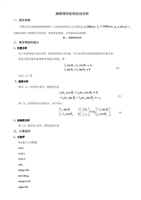
曲柄滑块机构运动分析一、相关参数在图1所示的曲柄滑块机构中,已知各构件的尺寸分别为mm l 1001=,mm l 3002=,s rad /101=ω,试确定连杆2和滑块3的位移、速度和加速度,并绘制出运动线图。
图1 曲柄滑块机构二、数学模型的建立1、位置分析为了对机构进行运动分析,将各构件表示为矢量,可写出各杆矢所构成的封闭矢量方程。
将各矢量分别向X 轴和Y 轴进行投影,得0sin sin cos cos 22112211=+=+θθθθl l S ll C(1) 由式(1)得2、速度分析将式(1)对时间t 求导,得速度关系C v l l l l =--=+222111222111sin sin 0cos cos θωθωθωθω(2) 将(2)式用矩阵形式来表示,如下所示⎥⎦⎤⎢⎣⎡-=⎥⎦⎤⎢⎣⎡⎥⎦⎤⎢⎣⎡-1111122222cos sin . 0 cos 1 sin θθωωθθl l v l lC(3) 3、加速度分析将(2)对时间t 求导,得加速度关系三、计算程序1、主程序%1.输入已知数据clear;l1=0.1;l2=0.3;e=0;hd=pi/180;du=180/pi;omega1=10;alpha1=0;%2.曲柄滑块机构运动计算for n1=1:721theta1(n1)=(n1-1)*hd;%调用函数slider_crank计算曲柄滑块机构位移、速度、加速度[theta2(n1),s3(n1),omega2(n1),v3(n1),alpha2(n1),a3(n1)]=slider_crank(theta1(n1),omega1,alpha1,l1,l2,e); endfigure(1);n1=0:720;subplot(2,3,1)plot(n1,theta2*du);title('连杆转角位移线图');xlabel('曲柄转角\theta_1/\circ');ylabel('连杆角位移/\circ');grid onsubplot(2,3,2)plot(n1,omega2);title('连杆角速度运动线图');xlabel('曲柄转角\theta_1/\circ');ylabel('连杆角速度/rad\cdots^{-1}');grid onsubplot(2,3,3)plot(n1,alpha2);title('连杆角加速度运动线图');xlabel('曲柄转角\theta_1/\circ');ylabel('连杆角加速度/rad\cdots^{-2}');grid onsubplot(2,3,4)plot(n1,s3);title('滑块位移线图');xlabel('曲柄转角\theta_1/\circ');ylabel('滑块位移/\m');grid onsubplot(2,3,5)plot(n1,v3);title('滑块速度运动线图');xlabel('曲柄转角\theta_1/\circ');ylabel('滑块速度/m\cdots^{-1}');grid onsubplot(2,3,6)plot(n1,a3);title('滑块加速度运动线图');xlabel('曲柄转角\theta_1/\circ');ylabel('滑块加速度/m\cdots^{-2}');grid on2、子程序function[theta2,s3,omega2,v3,alpha2,a3]=slider_crank(theta1,omega1,alpha1,l1,l2,e);%计算连杆2的角位移和滑块3的线位移s3=l1*cos(theta1)+l2*cos(theta2);theta2=asin((e-l1*sin(theta1))/l2);%计算连杆2的角速度和滑块3的线速度A=[l2*sin(theta2),1;-l2*cos(theta2),0];B=[-l1*sin(theta1);l1*cos(theta1)];omega=A\(omega1*B);omega2=omega(1);v3=omega(2);%计算连杆2的角加速度和滑块3的线加速度At=[omega2*l2*cos(theta2),0;omega2*l2*sin(theta2),0];Bt=[-omega1*l1*cos(theta1);-omega1*l1*sin(theta1)];alpha=A\(-At*omega+alpha1*B+omega1*Bt);alpha2=alpha(1);a3=alpha(2);四、程序运行结果及分析图2 运动规律曲线图从仿真曲线可以看出,当曲柄以w1=10rad/s匀速转动时,连杆的转角位移变化范围大约在-20~20度之间,在90°或270°有极值,呈反正弦变化趋势;连杆的角速度变化范围大约在-3.3~3.3rad/s,在0°或180°有极值,成反余弦变化趋势;连杆角加速度变化范围大约在-35~35rad/s2,在90°或270°有极值,呈正弦变化趋势。
机械原理课程机构设计实验报告题目:曲柄滑块机构的运动分析及应用小组成员与学号:刘泽陆(********)陈柯宇(11071177)熊宇飞(11071174)张保开(11071183)班级:1107172013年6月10日摘要 (3)曲柄滑块机构简介 (4)曲柄滑块机构定义 (4)曲柄滑块机构的特性及应用 (4)曲柄滑块机构的分类 (8)偏心轮机构简介 (9)曲柄滑块的动力学特性 (10)曲柄滑块的运动学特性 (11)曲柄滑块机构运行中的振动与平衡 (14)参考文献 (15)组员分工 (15)摘要本文着重介绍了曲柄滑块机构的结构,分类,用途,并进行了曲柄滑块机构的动力学和运动学分析,曲柄滑块机构的运动学特性分析,得出了机构压力表达式,曲柄滑块机构的运动特性分析,得出了滑块的位移、速度和加速度的运动表达式。
最后,对曲柄滑块机构运动中振动、平衡稳定性等进行了总结。
关键字:曲柄滑块动力与运动分析振动与平稳性ABSTRACTThe paper describes the composition of planar linkage, focusing on the structure, classification, use of a slider-crank mechanism and making the dynamic and kinematic analysis, kinematics characteristics of the crank slider mechanism analysis for a slider-crank mechanism, on one hand , we obtain the drive pressure of the slider-crank mechanism ,on the other hand,we obtain the expression of displacement, velocity and acceleration of movement. Finally, the movement of the vibration and balance stability of the crank slider mechanism are summarized.曲柄滑块机构简介曲柄滑块机构定义曲柄滑块机构是铰链四杆机构的演化形式,由若干刚性构件用低副(回转副、移动副)联接而成的一种机构。

曲柄滑块机构的运动分析及应用精编W O R D版IBM system office room 【A0816H-A0912AAAHH-GX8Q8-GNTHHJ8】机械原理课程机构设计实验报告题目:曲柄滑块机构的运动分析及应用小组成员与学号:刘泽陆(11071182)陈柯宇 (11071177)熊宇飞(11071174)张保开 (11071183)班级: 1107172013年6月10日摘要 (3)曲柄滑块机构简介 (4)曲柄滑块机构定义 (4)曲柄滑块机构的特性及应用 (4)曲柄滑块机构的分类 (8)偏心轮机构简介 (9)曲柄滑块的动力学特性 (10)曲柄滑块的运动学特性 (11)曲柄滑块机构运行中的振动与平衡 (14)参考文献 (15)组员分工 (15)摘要本文着重介绍了曲柄滑块机构的结构,分类,用途,并进行了曲柄滑块机构的动力学和运动学分析,曲柄滑块机构的运动学特性分析,得出了机构压力表达式,曲柄滑块机构的运动特性分析,得出了滑块的位移、速度和加速度的运动表达式。
最后,对曲柄滑块机构运动中振动、平衡稳定性等进行了总结。
关键字:曲柄滑块动力与运动分析振动与平稳性ABSTRACTThe paper describes the composition of planar linkage, focusing on the structure, classification, use of a slider-crank mechanism and making the dynamic and kinematic analysis, kinematics characteristics of the crank slider mechanism analysis for a slider-crank mechanism, on one hand , we obtain the drive pressure of the slider-crank mechanism ,on the other hand,we obtain the expression of displacement, velocity and acceleration of movement. Finally, the movement of the vibration and balance stability of the crank slider mechanism are summarized.曲柄滑块机构简介曲柄滑块机构定义曲柄滑块机构是铰链四杆机构的演化形式,由若干刚性构件用低副(回转副、移动副)联接而成的一种机构。
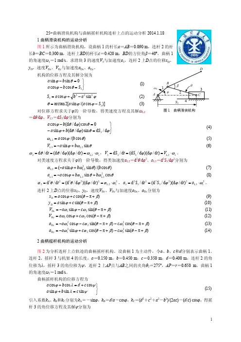
曲柄摇杆机构的运动分析研究作者:黄帆来源:《科技视界》2016年第01期【摘要】本文介绍平面连杆机构运动分析杆组法,并针对曲柄摇杆机构的运动特性进行分析,给出了曲柄摇杆的数值参数设计方面的理论依据。
【关键词】曲柄摇杆;运动分析;急回特性【Abstract】This paper introduces the kinematic analysis of the planar linkage mechanism,analyzes the kinematic characteristics of the crank and rocker mechanism, and gives the theoretical basis of the numerical parameters design of the crank rocker.【Key words】Crank and rocker; Motion analysis; Quick return characteristics0 前言曲柄摇杆机构是一种典型的四杆机构之一,由曲柄、摇杆、连杆、机架组成的。
曲柄或摇杆通过直接接触将预定的运动传给从动件。
由于曲柄摇杆机构可以实现各种复杂的运动要求,而且具有结构简单紧凑的特点,所以广泛应用于各种自动化机器、仪器和装配线,例如在纺织机械、印刷机械以及一些控制系统等装置中,广泛应用着各种类型的曲柄摇杆机构。
具有急回特性的曲柄摇杆机构是常用的曲柄摇杆机构,曲柄的转动使从动件按预定的运动规律摆动。
由于曲柄摇杆机构的运动特征依赖于曲柄、摇杆、连杆的长度和行程速比的类型,在常规设计中,为了获得从动件的预定输出运动(位移、速度和加速度),必须合理选择从动件的类型和机构参数后精确地设计曲柄摇杆的数值参数。
1 平面连杆机构运动分析杆组法简介平面连杆机构的运动分析,早已有成熟的算法,其中阿氏杆组法最为简单有效。
大部分连杆机构都是在基本机构上增加一个或多个常用的阿氏杆组构成的。

机械原理课程机构设计实验报告题目:曲柄滑块机构的运动分析及应用小组成员与学号:泽陆(11071182)柯宇(11071177)熊宇飞(11071174)保开(11071183)班级:1107172013年6月10日摘要 (3)曲柄滑块机构简介 (4)曲柄滑块机构定义 (4)曲柄滑块机构的特性及应用 (4)曲柄滑块机构的分类 (8)偏心轮机构简介 (9)曲柄滑块的动力学特性 (10)曲柄滑块的运动学特性 (11)曲柄滑块机构运行中的振动与平衡 (14)参考文献 (15)组员分工 (15)摘要本文着重介绍了曲柄滑块机构的结构,分类,用途,并进行了曲柄滑块机构的动力学和运动学分析,曲柄滑块机构的运动学特性分析,得出了机构压力表达式,曲柄滑块机构的运动特性分析,得出了滑块的位移、速度和加速度的运动表达式。
最后,对曲柄滑块机构运动中振动、平衡稳定性等进行了总结。
关键字:曲柄滑块动力与运动分析振动与平稳性ABSTRACTThe paper describes the composition of planar linkage, focusing on the structure, classification, use of a slider-crank mechanism and making the dynamic and kinematic analysis, kinematics characteristics of the crank slider mechanism analysis for a slider-crank mechanism, on one hand , we obtain the drive pressure of the slider-crank mechanism ,on the other hand,we obtain the expression of displacement, velocity and acceleration of movement. Finally, the movement of the vibration and balance stability of the crank slider mechanism are summarized.曲柄滑块机构简介曲柄滑块机构定义曲柄滑块机构是铰链四杆机构的演化形式,由若干刚性构件用低副(回转副、移动副)联接而成的一种机构。
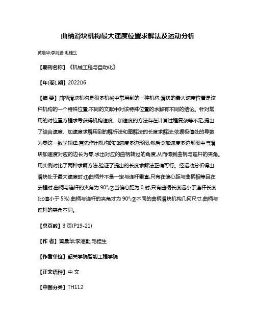
曲柄滑块机构最大速度位置求解法及运动分析
黄晨华;李湘勤;毛桂生
【期刊名称】《机械工程与自动化》
【年(卷),期】2022()6
【摘要】曲柄滑块机构是很多机械中常用到的一种机构,滑块的最大速度位置是该种机构的一个特殊位置,不同的文献中对该特殊位置的求解有不同的结论。
针对常
用的对位置方程求导获得机构速度、加速度的方法存在计算过程复杂等不足,提出
了结合速度、加速度求解用到的解析法和图解法的长度求解法:依据极值处的导数
为零这一数学规律,首先作出机构的加速度多边形图,然后令加速度多边形图中与滑
块加速度对应的边长为零,求出对应的曲柄转过的角度,从而得到曲柄与连杆的夹角。
用实例对比了两种求解方法,验证了提出的长度求解法正确可行。
经运动分析得出
滑块处于最大速度时:①曲柄并不是一定与连杆垂直,只有在偏心距与曲柄相等且在
去程时,曲柄与连杆的夹角为90°;②当偏心距为0时,只有曲柄长度远小于连杆长度(比值小于5%),曲柄与连杆的夹角才为90°;③不同的曲柄滑块机构几何尺寸,曲柄与连杆的夹角不同。
【总页数】3页(P19-21)
【作者】黄晨华;李湘勤;毛桂生
【作者单位】韶关学院智能工程学院
【正文语种】中文
【中图分类】TH112
【相关文献】
1.曲柄滑块机构中滑块最大速度的位置探讨
2.曲柄滑块机构运动分析的简便图解法
3.简便的曲柄滑块机构运动分析图解法及其证明
4.曲柄滑块机构运动分析的简便图解法
5.求曲柄滑块机构滑块加速度的速度瞬心法
因版权原因,仅展示原文概要,查看原文内容请购买。
学生实验报告实验课程名称:数学实验实验内容:曲柄滑块机构的运动规律学生姓名侯耀伟学号 1312211105 提交时间: 2015 年 3 月 27 日评分标准:目录1.实验目的-------------------------------------------------------------------22.实验问----------------------------------------------------------------------23.建立数学模型------------------------------------------------------------34.数学近似模型------------------------------------------------------------35.问题的解法与讨论-----------------------------------------------------66.程序设计-----------------------------------------------------------------107.总结------------------------------------------------------------------------111实验目的本实验主要涉及微积分中对函数特性的研究。
通过实验复习函数求导法、Taylor公式和其他有关知识。
着重介绍运用建立近似模型并进行数值计算来研究函数的方法。
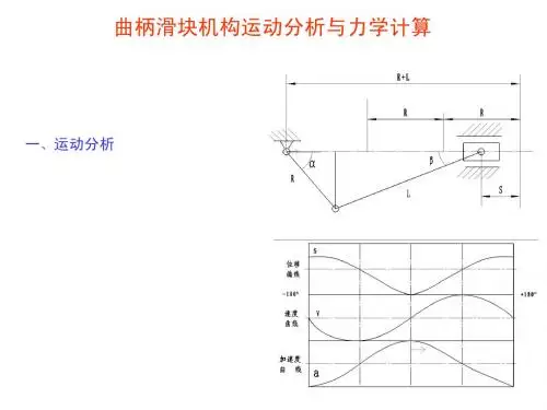
2实验问题曲柄滑块机构是一种常用的机械结构,它将曲柄的转动转化为滑块在直线上的往复运动,是压气机、冲床、活塞式水泵等机械的主机构。
记曲柄OQ的长为r,连杆QP的长为l,当曲柄绕固定点O以角速度ω旋转时,由连杆带动滑块P在水平槽内作往复直线运动。
假设初始时刻曲柄的端点Q位于水平线段OP上,曲柄从初始位置起转动的角度为θ,连杆QP与OP的锐夹角为β(称为摆角)。
机械原理课程机构设计实验报告题目:曲柄滑块机构的运动分析及应用小组成员与学号:刘泽陆(11071182)陈柯宇 (11071177)熊宇飞(11071174)张保开(11071183)班级:1107172013年6月10日摘要 (2)曲柄滑块机构简介 (3)曲柄滑块机构定义 (3)曲柄滑块机构的特性及应用 (3)曲柄滑块机构的分类 (4)偏心轮机构简介 (5)曲柄滑块的动力学特性 (5)曲柄滑块的运动学特性 (7)曲柄滑块机构运行中的振动与平衡 (9)参考文献 (10)组员分工 (11)摘要本文着重介绍了曲柄滑块机构的结构,分类,用途,并进行了曲柄滑块机构的动力学和运动学分析,曲柄滑块机构的运动学特性分析,得出了机构压力表达式,曲柄滑块机构的运动特性分析,得出了滑块的位移、速度和加速度的运动表达式。
最后,对曲柄滑块机构运动中振动、平衡稳定性等进行了总结。
关键字:曲柄滑块动力与运动分析振动与平稳性ABSTRACTThe paper describes the composition of planar linkage, focusing on the structure, classification, use of a slider-crank mechanism and making the dynamic and kinematic analysis, kinematics characteristics of the crank slider mechanism analysis for a slider-crank mechanism, on one hand , we obtain the drive pressure of the slider-crank mechanism ,on the other hand,we obtain the expression of displacement, velocity and acceleration of movement. Finally, the movement of the vibration and balance stability of the crank slider mechanism are summarized.曲柄滑块机构简介曲柄滑块机构定义曲柄滑块机构是铰链四杆机构的演化形式,由若干刚性构件用低副(回转副、移动副)联接而成的一种机构。
曲柄滑块机构运动分析的简便图解法曲柄滑块机构是一种具有复杂运动特性的机械系统,它在许多机械系统中起着重要的作用,能够提供有效的运动和力学参数。
因此,对曲柄滑块机构的正确分析和计算尤为重要。
近年来,研究人员们不断提出了各种新的方法来分析曲柄滑块机构的运动特性,如矩阵方法、积分方法等。
但是,这些方法都比较复杂,容易出错。
鉴于此,为了更简单地分析曲柄滑块机构的运动特性,本文提出了一种基于简单图解法的曲柄滑块机构运动分析方法。
首先,简单图解法用图形化的方式表示曲柄滑块机构的工作原理,可以清楚地展示曲柄滑块机构的运动特性,从而更容易理解它的工作原理及特性。
其次,在基于简单图解法的曲柄滑块机构运动分析中,需要考虑曲柄与滑块的结构参数,即弹性参数、刚度参数以及惯性参数等,以及滑块动力学输入信号,如外加载荷、内力和外力等。
根据这些参数和动力学信号,我们可以通过图解法求解曲柄滑块机构的运动特性,从而计算曲柄滑块的运动参数,如瞬时位置、速度、加速度等。
此外,基于简单图解法的曲柄滑块机构运动分析具有一定的普适性,可以用于分析各种类型的曲柄滑块机构,如拉伸曲柄滑块机构、蜗杆曲柄滑块机构、压簧曲柄滑块机构等。
因此,本文提出的基于简单图解法的曲柄滑块机构运动分析方法,对于分析各种曲柄滑块机构的运动特性具有重要的意义。
本文证明了简单图解法可以有效地分析曲柄滑块机构的运动特性,从而计算曲柄滑块机构的运动参数。
本文给出的分析过程,可以用来计算各种类型的曲柄滑块机构的运动特性,从而帮助工程师设计和优化曲柄滑块机构。
综上所述,本文提出的简单图解法分析曲柄滑块机构的运动特性是一种有效的方法,可以帮助工程师正确计算曲柄滑块机构的运动参数,从而更好地提高机械设备的工作效率和性能。
通过对简单图解法分析曲柄滑块机构运动特性的研究,可以为未来对曲柄滑块机构运动分析方法的设计和优化提供重要的参考和借鉴。
总之,简单图解法可以有效地分析曲柄滑块机构的运动特性和运动参数,是机械分析中非常有用的一种方法,有助于提高机械设备的性能和效率。
% 曲柄摇杆机构运动分析% (1)-计算连杆的输出角th3和摇杆的输出角th4% 设定各杆的长度(单位:毫米)rs(1)=304.8; % 设定机架1长度rs(2)=101.6; % 设定曲柄2长度rs(3)=254.0; % 设定连杆3长度rs(4)=177.8; % 设定摇杆4长度dr=pi/180.0;% 角度与弧度的转换系数% 设定初始推测的输入% 机构的初始位置th(1)=0.0; % 设定曲柄2初始位置角是0度(与机架1共线)th(2)=45*dr; % 连杆3的初始位置角是45度th(3)=135*dr; % 摇杆4的初始位置角是135度% 摇杆4的初始位置角可以用三角形的正弦定理确定th(3)=pi-asin(sin(th(2))*rs(3)/rs(4));dth=5*dr; % 循环增量% 曲柄输入角从0度变化到360度,步长为5度,计算th34for i=1:72[th3,th4]=ntrps(th,rs); % 调用牛顿—辛普森方程求解机构位置解非线性方程函数文件% Store results in a matrix-th34,in degrees% 在矩阵th34中储存结果,以度为单位;(i,:)表示第i行所有列的元素;(:,i)表示第i列所有行的元素th34(i,:)=[th(1)/dr th3/dr th4/dr]; % 矩阵[曲柄转角连杆转角摇杆转角]th(1)=th(1)+dth; % 曲柄转角递增th(2)=th3; % 连杆转角中间计算值th(3)=th4; % 摇杆转角中间计算值end% 求解曲柄摇杆机构中连杆的输出角th(3)和摇杆的输出角th(4)—函数文件function [th3,th4]=ntrps(th,rs)% 使用基于牛顿—辛普森方程解答四杆机构位置的非线性问题% 变量设置% th(1)=theta_2 % 输入变量% th(2)=theta_3_bar(starting guess) % 输出变量% th(3)=theta_4_bar(starting guess) % 输出变量% rs(1)=r_1,机架长度;rs(2)=r_2,曲柄长度;rs(3)=r_3,rs(4)=r_4,摇杆长度th2=th(1);th3bar=th(2);th4bar=th(3);% 设定收敛条件epsilon=1.0E-6;% 计算二维矢量的函数% 四杆机构闭环矢量方程的矩阵形式f=[rs(3)*cos(th3bar)-rs(4)*cos(th4bar)+rs(2)*cos(th2)-rs(1);rs(3)*sin(th3bar)-rs(4)*sin(th4bar)+rs(2)*sin(th2)];% 重复计算每个方程式的修正量因子while norm(f)>epsilonJ=[-rs(3)*sin(th3bar) rs(4)*sin(th4bar); rs(3)*cos(th3bar) -rs(4)*cos(th4bar)];dth=inv(J)*(-1.0*f);th3bar=th3bar+dth(1);th4bar=th4bar+dth(2);% 四杆机构闭环矢量方程的矩阵形式f=[rs(3)*cos(th3bar)-rs(4)*cos(th4bar)+rs(2)*cos(th2)-rs(1);rs(3)*sin(th3bar)-rs(4)*sin(th4bar)+rs(2)*sin(th2)];norm(f); % 计算矩阵或向量的范数(模)end;th3=th3bar; % 弧度值th4=th4bar; % 弧度值% 绘制输出角th(2)与th(3)—输入角th(1)的关系曲线subplot(2,2,1) % 选择第1个子窗口plot(th34(:,1),th34(:,2),th34(:,1),th34(:,3))axis([0 360 0 170])grid % 网格线ylabel('从动件角位移/deg')title('角位移线图')text(110,110,'摇杆4角位移')text(50,35,'连杆3角位移')% (2)-计算连杆的角速度om3和摇杆的角速度om4% Setting initial conditions% 设置初始条件om2=250; % 曲柄角速度(等速输入)T=2*pi/om2; % 机构周期-曲柄旋转1周的时间(秒)% 曲柄输入角从0度变化到360度,步长为5度,计算om34for i=1:72ct(2)=i*dth;A=[-rs(3)*sin(th34(i,2)*dr) rs(4)*sin(th34(i,3)*dr); rs(3)*cos(th34(i,2)*dr) -rs(4)*cos(th34(i,3)*dr)];B=[om2*rs(2)*sin(ct(2));-om2*rs(2)*cos(ct(2))];om=inv(A)*B; % 输出角速度矩阵om3=om(1);om4=om(2);om34(i,:)=[i om3 om4]; % 矩阵[序号连杆角速度摇杆角速度]t(i)=i*T/72;end% 绘制连杆的角速度om3和摇杆的角速度om4—时间Times的关系曲线subplot(2,2,2) % 选择第2个子窗口plot(t,om34(:,2),t,om34(:,3))axis([0 0.026 -190 210])grid % 网格线title('角速度线图')ylabel('从动件角速度/rad/s')text(0.001,170,'摇杆4角速度')text(0.013,130,'连杆3角速度')% (3)-计算连杆的角加速度a3和摇杆的角加速度a4a2=0; % 曲柄角速度是等速,角加速度a2=dom2/dt=0% 曲柄输入角从0度变化到360度,步长为5度,计算a34for i=1:72c(2)=i*dth;C=[-rs(3)*sin(th34(i,2)*dr) rs(4)*sin(th34(i,3)*dr); rs(3)*cos(th34(i,2)*dr) -rs(4)*cos(th34(i,3)*dr)];D(1)=a2*rs(2)*sin(c(2))+om2^2*rs(2)*cos(c(2))+om34(i,2)^2*rs(3)*cos(th34(i,2)*dr)-om34(i,3)^2*rs( 4)*cos(th34(i,3)*dr);D(2)=-a2*rs(2)*cos(c(2))+om2^2*rs(2)*sin(c(2))+om34(i,2)^2*rs(3)*sin(th34(i,2)*dr)-om34(i,3) ^2*rs(4)*sin(th34(i,3)*dr);a=inv(C)*D'; % 输出角加速度矩阵a3=a(1);a4=a(2);a34(i,:)=[i a3 a4]; % 矩阵[序号连杆角加速度摇杆加角速度]t(i)=i*T/72;end% 绘制连杆的角加速度a3和摇杆的角加速度a4—时间Times的关系曲线subplot(2,2,3) % 选择第3个子窗口plot(t,a34(:,2),t,a34(:,3))axis([0 0.026 -6*1e4 8*1e4])grid % 网格线title('角加速度线图')xlabel('时间/s')ylabel('从动件加速度/rad/s^{2}')text(0.003,6.2*1e4,'摇杆4角加速度')text(0.010,3.3*1e4,'连杆3角加速度')%% 输出1:四杆机构运动周期(0:5:360),时间,角位移,角速度,角加速度数据disp ' 曲柄转角连杆转角-摇杆转角-连杆角速度-摇杆角速度-连杆加速度-摇杆加速度' ydcs=[th34(:,1),th34(:,2),th34(:,3),om34(:,2),om34(:,3),a34(:,2),a34(:,3)];disp (ydcs)% 输出参数的数量级必须一致%% (4)-运动误差分析% 闭环矢量方程:r2+r3-r4-r1=0% 误差矢量E=r2+r3-r4-r1的模是表示仿真有效程度的标量(ex和ey是误差分量)ex=rs(2)*cos(th34(:,1)*dth)+rs(3)*cos(th34(:,2)*dth)-rs(4)*cos(th34(:,3)*dth)-rs(1); ey=rs(2)*sin(th34(:,2)*dth)+rs(3)*sin(th34(:,2)*dth)-rs(4)*sin(th34(:,3)*dth);ee=norm([ex ey]); % 计算误差矢量矩阵的范数(模) %% 输出2:四杆机构运动周期(0:5:360),时间,X向误差分量,Y向误差分量disp ' 曲柄转角时间(秒) X向误差Y向误差'wc=[th34(:,1),t(:),ex(:,1),ey(:,1)];disp (wc)fprintf (1,' 误差矢量矩阵的模ee = %3.4f \n',ee)%% 绘制均方根相容性误差曲线subplot(2,2,4) % 选择第4个子窗口plot(t,ex(:,1),t,ey(:,1))axis([0 0.026 -800 600])grid % 网格线title('均方根误差曲线')xlabel('时间/s')ylabel('均方根误差')text(0.012,350,'X向误差分量')text(0.003,-600,'Y向误差分量')。