H7710产品手册
- 格式:pdf
- 大小:1.87 MB
- 文档页数:57

P/N: 1802077100016*1802077100016*PT-7710 Series Quick Installation GuideMoxa PowerTrans SwitchVersion 7.1, January 2021Technical Support Contact Information /support2021 Moxa Inc. All rights reserved.Package ChecklistThe Moxa PowerTrans switch is shipped with the following items. If any of these items are missing or damaged, please contact your customer service representative for assistance.• 1 Moxa PowerTrans Switch•RJ45 to DB9 console port cable• 2 rack-mount ears or wall-mount ears•Quick installation guide (printed)•Warranty cardPanel Layout1.System status LEDs2.Interface module mode LEDs3.Interface module port LEDs4.Push-button switch to select mode for Interface Module5.Model name6.Fast Ethernet interface modules7.Gigabit Ethernet interface modules8.Serial console port9.10-pin terminal block for power inputs, and relay output10.Rack mounting kit11.Wall mounting kitDimensions (unit = mm)Fast Ethernet Interface Modules (slot 1)Gigabit / Fast Ethernet Interface Modules (slot 2)Rack MountingUse four screws to attach the PT switch to astandard rack.Wall MountingUse four screws to attach the PT switch to a Moxa wall mounting kit.Wiring RequirementsGrounding the Moxa PowerTrans SwitchGrounding and wire routing help limit the effects of noise due to electromagnetic interference (EMI). Run the ground connection from the ground screw to the grounding surface prior to connecting devices.Wiring the Power Input (110/220 VDC/VAC models)The PT-7710 (110/220VDC/VAC models) hasone power supply and oneset of power inputs,referred to as power input1. The front view of theterminal block connectoris shown here.STEP 1: Insert the L/N AC wires into the PWR1 terminals (L → pin 1, N → pin 2).STEP 2: To keep the AC wires from pulling loose, use a screwdriver to tighten the wire-clamp screws on the front of the terminal block. Wiring the Redundant Power Inputs (12/24/48 VDC models)The PT-7710 (12/24/48VDC models) has onepower supply and twosets of power inputs,referred to as power input1 and power input 2. Thefront view of the terminalblock connector is shownhere.STEP 1: Insert the dual set positive/negative DC wires into PWR1 and PWR2 terminals (+ → pins 1, 9; - → pins 2, 10).STEP 2: To keep the DC wires from pulling loose, use a screwdriver to tighten the wire-clamp screws on the front of the terminal block. Wiring the Relay ContactEach PT switch has onerelay output. Refer to thenext section for detailedinstructions on how toconnect the wires to theterminal block connector,and how to attach theterminal block connector to the terminal block receptor.FAULT: The RELAY contacts of the 10-pin terminal block connector are used to detect user-configured events. The two wires attached to the RELAY contacts form an open circuit when a user-configured event is triggered. If a user-configured event does not occur, the RELAY circuit will be closed.LED IndicatorsThe front panel of the PT switch contains several LED indicators. The function of each LED is described in the table below.LED Color State DescriptionSTAT GREENOnSystem has passed self-diagnosis teston boot-up and is ready to run.BlinkingSystem is undergoing the self-diagnosis test.RED OnSystem failed self-diagnosis on boot-up.PWR1 AMBER OnPower is being supplied to the mainmodule’s power input PWR1.OffPower is not being supplied to themain module’s power input PWR1.PWR2 AMBER OnPower is being supplied to the mainmodule’s power input PWR2.OffPower is not being supplied to themain module’s power input PWR2.FAULT RED OnThe corresponding PORT alarm isenabled and a user-configured eventhas been triggered.OffThe corresponding PORT alarm isenabled and a user-configured eventhas not been triggered, or thecorresponding PORT alarm is disabled.MSTR/HEAD GREENOnThis PT switch is set as the Master ofthe Turbo Ring, or as the Head of theTurbo Chain.BlinkingThe PT switch has become the RingMaster of the Turbo Ring, or the Headof the Turbo Chain, after the TurboRing or the Turbo Chain went down. OffThe PT switch is not the Master of thisTurbo Ring or is set as a Member ofthe Turbo Chain.CPLR/TAIL GREENOnWhen this PT switch is enabled toform a back-up path, or it is set asthe Tail of the Turbo Chain. Blinking Turbo Chain is down.OffThis PT switch disabled the couplingfunction, or is set as a Member of theTurbo Chain.LED Color State DescriptionLNK/ACT GREENOnThe corresponding module port’s linkis active.BlinkingThe corresponding module port’s datais being transmitted.OffThe corresponding module port’s linkis inactive.SPEED GREENOffThe corresponding module port’s datais being transmitted at 10 Mbps.OnThe corresponding module port’s datais being transmitted at 100 Mbps. BlinkingThe corresponding module port’s datais being transmitted at1000 Mbps.FDX/HDX GREEN OnThe corresponding module port’s datais being transmitted in full duplexmode.OffThe corresponding module port’s datais being transmitted in half duplexmode.RING/CHAIN PORT GREEN OnThe corresponding module’s port isthe ring or chain port of this PTswitch.OffThe corresponding module’s port isnot the ring or chain port of this PTswitch.COUPLERPORT GREEN OnThe corresponding module’s port isthe coupler port of this PT switch. OffThe corresponding module’s port isnot the coupler port of this PT switch.*Slot 2 (M2) is mainly used for Gigabit modules. If 100BaseFX modules are used in Slot 2 (M2), the modules will not support “Far End Fault”. The Link/ACT LED indicator will stay at “Green (ON)” status when Fiber TX cable is unplugged.SpecificationsTechnologyStandards IEEE 802.3, 802.3u, 802.3ab, 802.3z, 802.3x,802.1D, 802.1W, 802.1Q, 802.1p, 802.1X, 802.3ad Flow control IEEE 802.3x flow control, back pressure flowcontrolInterfaceFast Ethernet Slot 1 (M1) for any combination of 4-,6-, 7-, or 8-port PM-7200 fast Ethernet modules with10/100BaseT(X) (TP/M12 interface) or 100BaseFX(SC/ST connector), or 100BaseSFP; Slot 2 (M2) fora 1- or 2-port interface modules with 100BaseFX(SC/ST connector)Gigabit Ethernet Slot 2 (M2) for 2-port PM-7200 Gigabit Ethernetcombo module with 100/1000BaseT(X) or1000BaseSFP slots (Slot 2 does not support 10MFDX/HDX)Console RS-232 (RJ45)System LED Indicators STAT, PWR1, PWR2, FAULT, MSTR/HEAD, CPLR/TAILMode LED Indicators LNK/ACT, FDX/HDX, RING/CHAIN PORT, COUPLER PORT, SPEEDAlarm Contact One relay output with current carrying capacity of3A @ 30 VDC or 3A @ 240 VACOptical Fiber (100BaseFX)Distance Multi-mode:0 to 5 km, 1300 nm (50/125 μm, 800 MHz*km)0 to 4 km, 1300 nm (62.5/125 μm, 500 MHz*km)Single-mode:0 to 40 km, 1310 nm (9/125 μm, 3.5 PS/(nm*km)) Min. TX Output Multi-mode: -20 dBm; single-mode: -5 dbm Max. TX Output Multi-mode: -10 dBm; single-mode: 0 dbmRX Sensitivity Multi-mode: -32 dBm; single-mode: -34 dbm PowerInput Voltage 12/24/48 VDC (9 to 60 V), or 110/220 VDC/VAC(88 to 300 VDC and 85 to 264 VAC)Input Current Max. 0.81 A @ 24 VDCMax. 0.42 A @ 48 VDCMax. 0.17/0.10 A @ 110/220 VDCMax. 0.38/0.20 A @ 110/220 VACPhysical CharacteristicsHousing IP30 protection, metal caseDimensions(W x H x D)266.7 x 44 x 195 mm (10.5 x 1.73 x 7.68 in.) Weight 2200 gEnvironmental LimitsOperating Temp. -40 to 85°C (-40 to 185°F)Cold start of min. 100 VAC at -40°CStorage Temp. -40 to 85°C (-40 to 185°F)Ambient RelativeHumidity.5 to 95% (non-condensing)Regulatory ApprovalsSafety EN 60950-1, CSA C22.2 No. 60950-1, EN 60950-1 Power Automation IEC 61850-3, IEEE 1613Road Traffic NEMA TS2Rail Traffic EN 50121-4, EN 50155 (complies with a portion ofEN 50155 specifications)EMI FCC Part 15, CISPR (EN 55032) class AWarrantyWarranty Period 5 yearsDetails See /warranty。
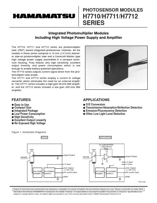
Subject to local technical requirements and regulations, availability of products included in this promotional material may vary. Please consult with our sales office. subject to change without notice. No patent rights are granted to any of the circuits described herein. ©2000 Hamamatsu Photonics K.Kq TYPICAL CHARACTERISTICS (Control Voltage: +1 V dc, Ta: 25 °C)STANDARD PHOTOSENSOR MODULESSPECIFICATIONSPHOTOSENSOR MODULES H7710/H7711/H7712 SERIESType No.H7710-01H7710-02H7710-03H7710-04H7711-01H7711-02H7711-03H7711-04H7712-01H7712-02H7712-03H7712-04H7710-01H7710-02H7710-03H7710-04H7711-01H7711-02H7711-03H7711-04H7712-01H7712-02H7712-03H7712-04H7710-01H7710-02H7710-03H7710-04H7711-01H7711-02H7711-03H7711-04H7712-01H7712-02H7712-03H7712-04H7710-01H7710-02H7710-03H7710-04H7711H7712H7710H7711H7712Spctral Range 185 nm to 750 nm 185 nm to 900 nm 185 nm to 900 nm 185 nm to 830 nm 185 nm to 750 nm 185 nm to 900 nm 185 nm to 900 nm 185 nm to 830 nm 185 nm to 750 nm 185 nm to 900 nm 185 nm to 900 nm 185 nm to 830 nmCurrent to Voltage Conversion FactorType No.Luminous Sensitivity (with 2856K light source)Radiant Sensitivity at Maximum Response -01: at 420 nm -02: at 600 nm -03: at 450 nm -04: at 530 nmDark CurrentOffset VoltageInduced Ripple in Signal *1Linearity *2Parameter700250020007007.0 × 1082.5 × 1092.0 × 1097.0 × 1087.0 × 1072.5 × 1082.0 × 1087.0 × 1075.2 × 1056.0 × 1054.2 × 1052.5 × 1055.2 × 10116.0 × 10114.2 × 10112.5 × 10115.2 × 10106.0 × 10104.2 × 10102.5 × 10101120.1±3±3144±0.5Value A/lm A/lm A/lm A/lm V/lm V/lm V/lm V/lm V/lm V/lm V/lm V/lm A/W A/W A/W A/W V/W V/W V/W V/W V/W V/W V/W V/W nA nA nA nA mV mV mV mV mV %Unit Amplifier Section————1 V/µA (1 M Ω)1 V/µA (1 M Ω)1V/µA (1 M Ω)1V/µA (1 M Ω)0.1 V/µA (100 k Ω)0.1 V/µA (100 k Ω)0.1 V/µA (100 k Ω)0.1 V/µA (100 k Ω)Bandwidth————DC to 20 kHz DC to 20 kHz DC to 20 kHz DC to 20 kHz DC to 200 kHz DC to 200 kHz DC to 200 kHz DC to 200 kHz*1: Measured across 1 M Ω/22 pF*2: PMT Output Current at 10 µA (DC Mode)Recommended Supply Voltage Range Supply Current (MAX.)(No Signal Input, Control Voltage: +1 V)Control Voltage to PMT Applied Voltage Ratio Sensitivity Adjustable Range (Relative Sensitivity)Settling Time (Sensitivity Control) (MAX.)Photosensitive Area Overall Dimensions WeightH7710H7711, H7712H7710 +15 V H7711, H7712 +15 V/-15 V Parameter+11.5 to +15.5±11.5 to ±15.577/11: 1031: 1042*3.7 × 13.019.0 × 50.8 × 53.2Approx. 100Value V dc V dc mA mA ——s mm mm gUnit q GENERAL* Against HV control voltage change of +1.0 V to +0.5 V.Supply Voltage Control Voltage Output CurrentOutput Voltage (In DC mode)Operating Temperature Storage TemperatureOperating/Storage HumidityH7710H7711, H7712H7710H7711H7712Parameter+18±18+1.2-10+10+1+5 to +50-20 to +5090*Value V dc V dc V dc µA V V °C °C % RHUnit q MAXIMUM RATINGS (Absolute Maximum Values)* With no moisture condensationFigure 2: Typical Spectral Responses (H7710)Figure 3: Typical Spectral Responses (H7711/H7712)0.1R A D I A N T S E N S I T I V I T Y (µA /n W )WAVELENGTH (nm)11010010000.1R A D I A N T S E N S I T I V I T Y (V /n W )R A D I A N T S E N S I T I V I T Y (V /n W )WAVELENGTH (nm)11010010000.010.1110100(H7711)(H7712)TPMOB0121EAFigure 4: Sensitivity Adjusting Characteristics (H7710)Figure 5: Sensitivity Adjusting Characteristics (H7711/H7712)Figure 6: DC Linearity of PMT Output (H7710)0.010.1101001000100001CONTROL VOLTAGE (V)R A D I A N T S E N S I T I V I T Y A T M A X I M U M R E S P O N S E (µA /n W )0.010.1101001000100001CONTROL VOLTAGE (V)R A D I A N T S E N S I T I V I T Y A T M A X I M U M R E S P O N S E (µA /n W )0.010.11010010001000010.0010.011101001000(H7711)(H7712)0.1CONTROL VOLTAGE (V)R A D I A N T S E N S I T I V I T Y A T M A X I M U M R E S P O N S E (V /n W )R A D I A N T S E N S I T I V I T Y A T M A X I M U M R E S P O N S E (V /n W )0.010.11010010001000010.0010.011101001000(H7711)(H7712)0.1CONTROL VOLTAGE (V)R A D I A N T S E N S I T I V I T Y A T M A X I M U M R E S P O N S E (V /n W )R A D I A N T S E N S I T I V I T Y A T M A X I M U M R E S P O N S E (V /n W )124810141-5.0-2.5+2.5+5.035PMT OUTPUT CURRENT (µA)D E V I A T I O N (%)TPMOC0133EATPMOA0013EAFigure 7: Wiring ExamplesFigure 8: Dimensional Outline (Unit: mm)+0.2 and +1.2 volts for gain adjustment.Making the HV control voltage 0 V de-energizes the PMT.The input impedance of "HV Control Input"is 100 k Ω.3)4)PHOTOSENSOR MODULES H7710/H7711/H7712 SERIESTPMO1014E01JUL. 2000 IP (500)HAMAMATSU PHOTONICS K.K., Electron Tube Center314-5, Shimokanzo, Toyooka-village, Iwata-gun, Shizuoka-ken, 438-0193, Japan, Telephone: (81)539/62-5248, Fax: (81)539/62-2205U.S.A.: Hamamatsu Corporation: 360 Foothill Road, P. O. Box 6910, Bridgewater. N.J. 08807-0910, U.S.A., Telephone: (1)908-231-0960, Fax: (1)908-231-1218 E-mail: usa@Germany: Hamamatsu Photonics Deutschland GmbH: Arzbergerstr. 10, D-82211 Herrsching am Ammersee, Germany, Telephone: (49)8152-375-0, Fax: (49)8152-2658 E-mail: info@hamamatsu.deFrance: Hamamatsu Photonics France S.A.R.L.: 8, Rue du Saule Trapu, Parc du Moulin de Massy, 91882 Massy Cedex, France, Telephone: (33)1 69 53 71 00, Fax: (33)1 69 53 71 10 E-mail: france@ United Kingdom: Hamamatsu Photonics UK Limited: Lough Point, 2 Gladbeck Way, Windmill Hill, Enfield, Middlesex EN2 7JA, United Kingdom, Telephone: 44(20)8-367-3560, Fax: 44(20)8-367-6384 E-mail: info@ North Europe: Hamamatsu Photonics Norden AB: Smidesvägen 12, SE-171-41 SOLNA, Sweden, Telephone: (46)8-509-031-00, Fax: (46)8-509-031-01 E-mail: info@hamamatsu.seItaly: Hamamatsu Photonics Italia: S.R.L.: Strada della Moia, 1/E, 20020 Arese, (Milano), Italy, Telephone: (39)02-935 81 733, Fax: (39)02-935 81 741 E-mail: info@hamamatsu.itHOMEPAGE URL 。
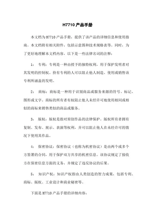
H7710产品手册本文档为H7710产品手册,提供了该产品的详细信息和使用指南。
本文档附有相关附件,包括示意图和技术规格表等。
同时,为了更好地理解本文档内容,以下是一些法律名词的注释:1:专利:专利是一种由授予的独特权利,用于保护发明者对其发明的控制权。
持有专利的人可以阻止他人制造、使用或销售该专利所涵盖的发明。
2:商标:商标是一种用于识别商品或服务来源的符号、标记、图形或文字。
商标的所有者有权阻止他人未经许可地使用相同或相似的商标来销售类似的商品或服务。
3:版权:版权是指对原创作品的法律保护。
版权所有者拥有复制、发布、展示、表演等权利,并可以阻止他人在未经许可的情况下使用其作品。
4:保密协议:保密协议(也称为机密协议)是由两个或多个方签署的合同,用于保护双方共享的机密信息。
该协议规定了接收方在保密信息方面的义务,并规定了违反协议的后果。
5:知识产权:知识产权指由人类创造的智力成果,包括专利、商标、版权、工业设计和商业秘密等。
下面是H7710产品手册的详细内容:1:产品概述1.1 产品名称1.2 产品型号1.3 产品特点1.4 产品应用范围1.5 主要组成部分2:技术规格2.1 外观尺寸2.2 重量2.3 电源要求2.4 工作温度范围2.5 存储温度范围2.6 网络连接2.7 通信协议2.8安全和合规性认证3:产品安装3.1 安装前准备3.2 安装步骤3.3 连接和布线4:产品使用指南4.1 启动和关闭4.2 主要功能操作说明 4.3 菜单导航4.4 高级设置4.5 故障排除5:常见问题解答5.1 问题一解答5.2 问题二解答5.3 问题三解答6:附件6.1 示意图6.2 技术规格表6.3 维修保养手册请注意,本文档所涉及的附件可以通过联系我们的客服人员或访问我们的官方网站获取。
本文档涉及的法律名词及注释旨在提供相关概念的简要解释,以帮助读者更好地理解本文档的内容。
然而,这些注释不能代替法律咨询或解释,如果在实际使用中遇到法律问题,请咨询专业律师。

菜单说明书目录1名词解释 (4)2进入配置菜单方法 (5)3配置菜单总列表 (6)4移动服务中心设置 (7)4.1服务代码 (7)4.2PPP用户名 (7)4.3PPP密码 (7)4.4SIM/UIM PIN (7)4.5接入点名称(APN) (7)5终端单元设置 (8)5.1DTU身份识别码 (8)5.2最大传输包长 (8)5.3最后包空闲时间间隔 (8)5.4数据包匹配标识 (8)5.5启用TDP协议 (9)5.6支持数据回执(*TDP) (9)5.7自动应答(*DDP) (10)5.8重拨号时间间隔 (10)5.9控制台信息类型 (10)6网络通道设置 (11)6.1通道工作模式 (11)6.2TCP保活时间间隔 (11)6.3PPP保活时间间隔 (12)6.4DNS IP地址 (12)6.5DSC IP地址 (12)6.6DSC域名 (13)6.7DSC通讯端口 (13)6.8本地通讯端口 (13)6.9连网方式 (13)6.10高级 (13)7用户串口设置 (18)7.1波特率 (18)7.2数据位 (18)7.3校验位 (18)7.4停止位 (19)7.5流控制 (19)8特殊选项设置 (20)8.1终端类型 (20)8.2呼叫类型 (20)8.3呼叫时间间隔 (20)8.4空闲下线时间间隔 (21)8.5空闲下线模式 (21)9DTU通道工作模式说明 (22)9.1单通道 (22)9.2主备通道 (22)9.3多通道 (23)10短信通道说明 (24)10.1DTU短信通道运行说明 (24)10.2短信通道配置 (24)10.3短信数据格式 (24)11TCP服务通道说明 (25)11.1TCP服务通道运行说明 (25)11.2TCP服务通道配置 (25)11.3 (25)12 (25)1名词解释DTU 宏电公司的无线数据传输单元DSC 数据服务中心,连接于internet网络,接收DTU数据的应用中心DDP DTU与DSC之间的数据交互协议TE 用户终端设备,连接于DTU的串口端TDP DTU与TE间的数据交互协议一直按住”空格”键,给DTU上电,直到DTU出现欢迎信息,然后按”C”键就可以进入配置菜单。

HE71x系列露点—湿球—温湿度计使用手册HE71x系列(包含HE710,HE715)露点湿球温湿度计,是一款测量相对湿度,空气温度,露点温度和湿球温度的综合性温湿度测量仪,它先进的功能包括数据保持,自动关机,背光源,以及最大最小值读数等功能。
HE71x系列温湿度计由华图公司自主设计、研发与生产,采用进口优质传感器,符合人体工程学设计原理,测量准确,使用方便,适合于各种环境空气温湿度专业测量。
1.1 产品特点l读数锁定,查看记录最大最小值。
l温湿度同时显示。
l温度单位一键切换℃/℉/K。
l采用原装进口温湿度传感器。
l独特设计,符合人体工程学原理,可保护传感器,外形美观大方。
1.2 使用范围农业研究、食品、医药、化工、气象、环保、实验室等领域。
1.3 性能参数测量范围温度:-20~+70℃(- 4~+158℉)湿度:0~100%RH露点温度DP:-21.6~70.0℃(-6.9~158℉) 湿球温度Wb:-78.7~70.0℃(-99.9~158℉)分辩率空气温度:0.1℃/℉相对湿度:0.1%RH 湿球温度:0.1℃/℉露点温度:0.1℃/℉准确度温度:±0.5℃(HE710)/±0.3℃(HE715)湿度:±3%RH(HE710) / ±2%RH(HE715)记录容量99组显示LCD液晶双排显示,同时显示温湿度数据。
反应时间 1.5秒操作环境 0-80%RH, 0-50℃LCD显示区域54 x44 mm产品尺寸275(L) x 96(W) x 44mm(T)产品重量约290克供电电源9V方块电池功耗指标 2.5mA(背光开)/ 1mA(背光关)附件电池,使用说明书,工具盒。
选购件三脚架、备用电池。
1.4 露点/湿球/温湿度计使用入门(1)按键和各组成部分LCD显示屏MAX/MIN:最大&最小记录值查看键CFK:切换℃/℉/K温度单位MEM:手动记录内存数据按键SETUP:进入设置模式按键,设置温度、湿型号标签度测量偏差值。

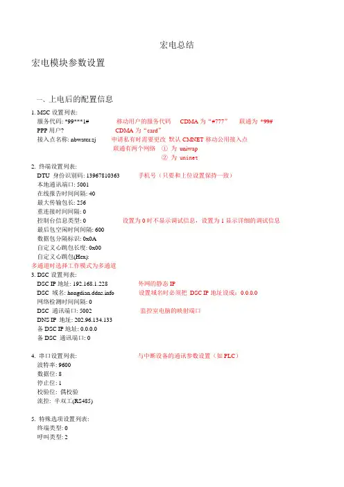
宏电总结宏电模块参数设置一、上电后的配置信息1. MSC设置列表:---服务代码: *99***1# 移动用户的服务代码CDMA为“#777”联通为*99# ---PPP用户? CDMA为“card”---接入点名称: nbwater.zj 申请私有时需要更改默认CMNET移动公用接入点联通有两个网络①为uniwap②为 uninet2. 终端设置列表:---DTU 身份识别码: 139******** 手机号(只要和上位设置保持一致)---本地通讯端口: 5001---在线报告时间间隔: 40---最大传输包长: 256---重连接时间间隔: 0---控制台信息类型: 0 设置为0时不显示调试信息,设置为1显示详细的调试信息---最后包空闲时间间隔: 600---数据包分隔标识: 0x0A---自定义心跳包长度: 0x00---自定义心跳包(Hex):多通道时选择工作模式为多通道3. DSC设置列表:---DSC IP地址: 192.168.1.228 外网的静态IP---DSC 域名: 设置域名时必须把DSC IP地址设成:0.0.0.0---网络检测时间间隔: 0---DSC 通讯端口: 5002 监控室电脑的映射端口---DNS IP 地址: 202.96.134.133---备DSC IP地址: 0.0.0.0---备DSC 通讯端口: 04. 串口设置列表: 与中断设备的通讯参数设置(如PLC)---波特率: 9600---数据位: 8---停止位: 1---校验位: 偶校验---流控: 半双工(RS485)5. 特殊选项设置列表:---终端类型: 0---呼叫类型: 2---呼叫时间间隔: 60---空闲下线时间间隔: 0---DSC身份识别码:---通讯协议选择(透明0/DDP协议1): 1 默认为1可以远程修改配置,透明时不可以---网络连接方式(UDP 0/TCP 1): 0 UDP可以有少量丢包,TCP有丢包就连接故障重新连接---TCP保活时间间隔: 5---PPP保活时间间隔: 0二、在线监测HDOS>r //输入“r”退出配置,DTU将自动拨号与DSC建立连接HDOS> //以下为DTU运行信息(软件版本不同运行信息会稍有差异)Hongdian H7000 GPRS DTU Software Suite 3.0.2-T //DTU软件版本Copyright (C) 2004-2008 Hongdian Inc.H/W: HWL92-7118-GM1V28050401 硬件平台DTU Identity Number:139******** 配置ID号Service Code:*99***1#PPP Username:Access Point Name:CMNETDSC IP Address:211.162.72.197DSC IP Port:5007Checking...要是无SIM卡会提示Searching GPRS network... //搜索网络Registered, home network. //注册网络Signal strength is <20>. //信号强度20---31为正常Module initialized. //模块初始化Dialing... //拨号不成功可能是欠费或是基站的问题或中心配置问题,端口映射的问题,等Dial successfully. //拨号成功,获得GPRS网络IP地址,5次都无返回重新返回Connecting with DSC...Connect OK.Registering DSC... //注册数据中心(DSC)Register OK. //登陆数据中心(DSC)成功如要显示更详细的调试信息进入高级功能里控制台类型设为3testtesttesttest //中心发来的数据也可恢复出厂的设置连接深圳的中心来检测模块是否有问题域名三、DSC DEMO使用调试DTU需要在中心启动DSC DEMO程序,用于向DTU发送和接收从DTU发来的数据,可以远程参数设置修改DTU的配置,通讯协议必须选择DDP协议。

;最近学用AD7710,用AD7710数据手册中的程序,怎么也不好用,没想到AD这么大公司数据手册中的程序居然很多错误。
在网上也没找到什么有价值的资料,无奈只好自己弄,用了好久终于解决,现在拿出来给大家参考。
鄙视一下收集网上资料拿来卖的人。
;这个程序烧写后运行通过,如果实际应用还需优化,学习够用了。
;采用单电源0-5V输入,2.5V参考电压,2.5V偏置电压,软件上设置了单极输入,接线图为AD7710数据手册中单电源接线图,只是增加了1602显示,见程序中说明。
;读AD数据时,AD首先输出的是数据最高位,最后是数据最低位;同样在对AD内部寄存器进行写操作时,;;应首先写入最高位,最后写入最低位。
AD7710内部有3个独立的24位寄存器,包括控制寄存器、数据寄存器和校正寄存器;A0为寄存器选择,当A0=0 时,读写操作均为控制寄存器,当A=1时,读操作为数据寄存器,而写操作则;为校正寄存器;当1、2通道同时输入23.6MV时,1通道AD数158356,2通道AD数1267582(增益为8)。
;1602连线图:; *DB0---P2.0* *DB4---P2.4* *RS-------------P3.7*; *DB1---P2.1* *DB5---P2.5* *RW-------------P3.6*; *DB2---P2.2* *DB6---P2.6* *E--------------P3.5* (参见说明书); *DB3---P2.3* *DB7---P2.7* *VLCD接10K可调电阻到GND*;注:89S51的晶振频率为6MHz,AD7710的晶振频率为8MHz;0010 0000 1011;通道0 AIN1 ,增益为1,24位精度;0110 0001 1010 ; FS11-FS0=061AH,每秒转换十次;0010 1110 1011 ;通道1 AIN2,增益为8,24位精度;0110 0001 1010 ; FS11-FS0=061AH,每秒转换十次;当1 2通道同时输入23.6MV时,1通道AD数158356,2通道AD数1267582(增益为8)。
菜单说明书目录1名词解释 (4)2进入配置菜单方法 (5)3配置菜单总列表 (6)4移动服务中心设置 (7)4.1服务代码 (7)4.2PPP用户名 (7)4.3PPP密码 (7)4.4SIM/UIM PIN (7)4.5接入点名称(APN) (7)5终端单元设置 (8)5.1DTU身份识别码 (8)5.2最大传输包长 (8)5.3最后包空闲时间间隔 (8)5.4数据包匹配标识 (8)5.5启用TDP协议 (9)5.6支持数据回执(*TDP) (9)5.7自动应答(*DDP) (10)5.8重拨号时间间隔 (10)5.9控制台信息类型 (10)6网络通道设置 (11)6.1通道工作模式 (11)6.2TCP保活时间间隔 (11)6.3PPP保活时间间隔 (12)6.4DNS IP地址 (12)6.5DSC IP地址 (12)6.6DSC域名 (13)6.7DSC通讯端口 (13)6.8本地通讯端口 (13)6.9连网方式 (13)6.10高级 (13)7用户串口设置 (18)7.1波特率 (18)7.2数据位 (18)7.3校验位 (18)7.4停止位 (19)7.5流控制 (19)8特殊选项设置 (20)8.1终端类型 (20)8.2呼叫类型 (20)8.3呼叫时间间隔 (20)8.4空闲下线时间间隔 (21)8.5空闲下线模式 (21)9DTU通道工作模式说明 (22)9.1单通道 (22)9.2主备通道 (22)9.3多通道 (23)10短信通道说明 (24)10.1DTU短信通道运行说明 (24)10.2短信通道配置 (24)10.3短信数据格式 (24)11TCP服务通道说明 (25)11.1TCP服务通道运行说明 (25)11.2TCP服务通道配置 (25)11.3 (25)12 (25)1名词解释DTU 宏电公司的无线数据传输单元DSC 数据服务中心,连接于internet网络,接收DTU数据的应用中心DDP DTU与DSC之间的数据交互协议TE 用户终端设备,连接于DTU的串口端TDP DTU与TE间的数据交互协议一直按住”空格”键,给DTU上电,直到DTU出现欢迎信息,然后按”C”键就可以进入配置菜单。
Quick Reference GuideModel No. KX-T7710 Important InformationWhen using the KX-T7710, keep the following conditions in mind.• If there is any problem, unplug the extension line and connect a known working phone. If the known working phone operates properly, have the defective phone repaired by a specified Panasonic Factory Service Centre. If the known working phone does not operate properly, check the Panasonic KX series Business Telephone System and the internal extension wiring.• Keep the unit away from heating appliances and electrical noise generating devices such as fluorescent lamps and motors.• The unit should be kept free of dust, moisture and vibration, and should not be exposed to direct sunlight.• Do not use benzine, thinner, or any abrasive powder to clean the cabinet. Wipe it with a soft cloth.• Do not disassemble this product. Dangerous electrical shock could result. The unit must only be disassembled and repaired by qualified service technicians.• Do not use any handset other than a Panasonic handset.• When a failure occurs which results in the internal parts becoming accessible, disconnect the telephone line cord immediately and return this unit to service centre. WARNING:TO PREVENT THE RISK OF FIRE OR ELECTRIC SHOCK, DO NOT EXPOSE THIS PRODUCT TO RAIN OR ANY TYPE OF MOISTURE.THIS HANDSET EARPIECE IS MAGNETISED AND MAY RETAIN SMALL FERROUS OBJECTS.IMPORTANT NOTICE:• The KX-T7710NZ shall not be set to make automatic calls to the Telecom 111 Emergency service.• The KX-T7710NZ is designed for use in New Zealand, and can only be used in New Zealand.Note:In this manual, the suffix of each model number is omitted.2003 Panasonic Communications Co., Ltd. All Rights Reserved.Off-hookOn-hookFeature numberTalk* "Location of Controls" is shown on page 6.Desired FunctionOperationCallingOne-touch DiallingCalling an operatorPersonalSpeed DiallingTo an extensionTo an external partyphone no.extension no.To dialMaking CallsThe REDIAL will dial the last number you called manually.line accessno.Press One-touch button ./Quick Diallingquick dial no.To store* The Feature numbers described in this manual are for KX-TE Series or KX-TDA Series. If a different Panasonic KX series Business Telephone System is connected, please refer to its manuals.To storedesired no.(max. 24 digits)/Press One-touch button .desired no.(TE: max. 24 digits)Redial(TDA: max. 32 digits)KX-TE Series KX-TDA SeriesTo dialKX-TE Series KX-TDA SeriesSystemSpeed DiallingTo dialKX-TE Series KX-TDA SeriesPersonal speeddial no.System speeddial no.Personal speeddial no.TDA: 00-99 (Default: 00-09)TE: 0-9TDA: 000-999TE: 00-99TDA: 00-99 (Default: 00-09)TE: 0-9When the Dialled Extension is Busy/No AnswerReceiverSenderTo call backMessage Waitingextension no.LeaveCancelTo leave/cancel a notification extension no.LeaveCancelKX-TE SeriesKX-TDA SeriesHolding To retrieve a call at the holding extension Announce.dial no.Holding a callTransferring a callDuring a ConversationKX-TE SeriesKX-TE SeriesKX-TDA Series* In Normal Mode, you should change the default setting for Message button.(See page 5.)If the handset has been replaced, just go off-hook.KX-TDA SeriesPagingAnnounce.All extensions & external speakersAll external speakersTo answer a pageTo pageLockUseful Featuresdesired phone no.Three-partyConferenceDuring a conversationLocking your extensionlock code lock codeAll extensionsGroupgroup no.paging group no.lock code UnlockLockUnlockextension PINAnnounce.You can make a voice announcement to extensions or external speakers or both in the preset group simultaneously.KX-TDA SeriesKX-TE SeriesKX-TE SeriesKX-TDA SeriesKX-TE SeriesKX-TDA SeriesOperations in NORMAL ModeOne-touch buttonsFive One-touch buttons can be used as a One-touch dialling button or to access a feature. Personal Speed DiallingYou can store Personal speed dial numbers up to 10 for KX-TE Series,and up to 100 for KX-TDA Series(Default: 10).MESSAGE ButtonYou can change the feature access number for the MESSAGE Button. [Default: 702] For more detail, refer to the manuals for the connected Panasonic KX series Business Telephone Systems.desired no.(max. 24 digits)Setting Lock/UnlockYou can lock the settings for one-touch buttons and MESSAGE button. [Default: Unlock]To lockTo unlockConfirmation in Programming ModeWhen programming, you can confirm your entry by three types of beep sound.• One long beep: Your entry is accepted.• Two beeps: Your entry is same as a previous entry.• Three beeps: Your entry is rejected.Memory Back UpIf the telephone line is disconnected for more than three days, the stored numbersfor One-touch dialling and Speed dialling will be erased. Please store them again. Also, the settings for MESSAGE and Flash time will return to the default settings. Flash TimeBefore programming the length of Flash time, make sure the position of the Mode switch lever is "NORMAL". Enter the appropriate selection number for your country. [Default: 100 ms]selection no.1: 80 ms, 2: 90 ms, 3: 100 ms,4: 110 ms, 5: 200 ms, 6: 300 ms,7: 400 ms, 8: 600 msRegarding other operations, please refer to the manuals for the connected Panasonic KX series Business Telephone Systems.Confirming the ModeAdjusting the RINGER VolumeAdjust the RINGER volume selector lever (at the bottom of the unit) to the desired setting. ( – LOW, – MIDDLE, – HIGH) [Default: MIDDLE]You can confirm the current mode by the position of the Mode switch lever (at the bottom of the unit). [Default: NORMAL]PAUSE: Used to insert a pause whenstoring a telephone number.AUTO: Used for Personal Speed dialling.PROGRAM: Used to enter theprogramming mode.MESSAGE: Used to call back the party who left the message waiting indication.Handset Volume Control Buttons: Used to adjust the handset volume.One-touch Buttons (M1-M5): Used to access a feature or as a One-touch dialling button.FLASH/RECALL: Used to send a flash signal in order to access a PBX feature (eg., Hold, Transfer, or Three-party Conference).REDIAL:Used to redial the last dialled number.PBX modeNORMAL modeConnecting a Communication DeviceTelephone Card: Has two sides (NORMAL mode, PBX mode).DATA PORTTo connect a communication device such as a computer modem to the telephone line, please use the DATA PORT (at the right side of the unit). RJ11 modular jack is available.PBX ModeNORMAL Mode Message/Ringer Lamp: Flashes when you receive a call or when someone has left you a message.One-touch Buttons (1-8): Used as a One-touch button which is set by the Panasonic KX series Business Telephone Systems ; youdo not need to programat your extension.The KX-T7710 has two modes, NORMAL Mode and Panasonic PBX Mode*.Please use the corresponding side of the Telephone Card depending on the mode.*The PBX Mode may not be available depending on the model of the connected Panasonic KX series Business T elephone Systems.For more detail, please consult your dealer.Location of ControlsRemoving the Telephone Card CoverTelephone line cordWallmounting adaptor123To temporarily place the handset down during a conversation:Wall Mounting12Things You Should KnowWe, Panasonic Communications Co., Ltd., declare that this equipment is in compliance with the essential requirements and other relevant provisions of Directive 1999/5/EC.If you want to get a copy of the original Declaration of Conformity of our products which relates to the R&TTE, please contact to our web address: http://doc.panasonic.deThis product is intended to be connected to Panasonic KX series Business Telephone Systems.Note: CE Standards do not apply to the KX-T7710NZ.83 mmPSQW1960XA KK0103DH2026(X, NZ)。
PT-7710SeriesIEC61850-38+2G-port Layer2Gigabit modular managed rackmount EthernetswitchesFeatures and Benefits•IEC61850-3,IEEE1613(power substations),and EN50121-4(railwayapplications)compliant•Complies with a portion of EN50155specifications•VLAN Unaware:Supports priority-tagged frames to be received by specificIEDs•Up to4ports with M12connectors•Turbo Ring and Turbo Chain(recovery time<20ms@250switches),1RSTP/STP,and MSTP for network redundancy•Universal power supply range,12/24/48VDC or110/220VDC/VAC•-40to85°C operating temperature rangeCertificationsIntroductionThe PT-7710is designed to meet the demands of power substation automation systems(IEC61850-3,IEEE1613),and railway applications(EN 50121-4).The PT-7710’s Gigabit and Fast Ethernet backbone,redundant ring,and12/24/48VDC redundant power inputs increase the reliability of the communications and reduce cabling and wiring costs.The modular design of the PT-7710makes network planning easy,and allows greater flexibility by letting you install up to2Gigabit ports and8Fast Ethernet ports,or10Fast Ethernet ports.Additional Features and Benefits•Command line interface(CLI)for quickly configuring major managed functions•VLAN Unaware:Supports priority-tagged frames to be received by specific IEDs•DHCP Option82for IP address assignment with different policies •EtherNet/IP and Modbus TCP industrial Ethernet protocols supported•Automatic recovery of connected device’s IP addresses•Line-swap fast recovery•IGMP snooping and GMRP for filtering multicast traffic from industrial Ethernet protocols •IEEE802.3ad,LACP for optimum bandwidth utilization•Bandwidth management to prevent unpredictable network status •Multi-port mirroring for online debugging•Automatic warning by exception through email and relay output •RMON for proactive and efficient network monitoring •Configurable by Web browser,Telnet/Serial console,CLI,Windows utility,and ABC-01automatic backup configurator•Turbo Ring and Turbo Chain(recovery time<20ms@250switches),1 RSTP/STP,and MSTP for network redundancyCybersecurity Features•User passwords with multiple levels of security protect against unauthorized configuration•SSH/HTTPS is used to encrypt passwords and data•Lock switch ports with802.1X port-based network access control so that only authorized clients can access the port•RADIUS/TACACS+allows you to manage passwords from a central location •802.1Q VLAN allows you to logically partition traffic transmitted between selected switch ports•Secure switch ports so that only specific devices and/or MAC addresses can access the ports•Disable one or more ports to block network traffic•SNMPv3provides encrypted authentication and access security1.Gigabit Ethernet recovery time<50msSpecificationsEthernet InterfaceCabling Direction PT-7710-F Series:Front cablingPT-7710-D Series:Down cablingCompatible Modules Slot1:PM-7200-8TX,PM-7200-2MSC4TX,PM-7200-2MST4TX,PM-7200-2SSC4TX,PM-7200-4MSC2TX,PM-7200-4MST2TX,PM-7200-4SSC2TX,PM-7200-6MSC,PM-7200-6MST,PM-7200-6SSC,PM-7200-8SFP,PM-7200-4M12,PM-7200-8MTRJSlot2:PM-7200-2GTXSFP,PM-7200-1MSC,PM-7200-1MST,PM-7200-2MSC,PM-7200-2MST,PM-7200-2SSCStandards IEEE802.1D-2004for Spanning Tree ProtocolIEEE802.1p for Class of ServiceIEEE802.1Q for VLAN TaggingIEEE802.1s for Multiple Spanning Tree ProtocolIEEE802.1w for Rapid Spanning Tree ProtocolIEEE802.1X for authenticationIEEE802.3for10BaseTIEEE802.3ab for1000BaseT(X)IEEE802.3ad for Port Trunk with LACPIEEE802.3u for100BaseT(X)and100BaseFXIEEE802.3x for flow controlIEEE802.3z for1000BaseSX/LX/LHX/ZXEthernet Software FeaturesFilter802.1Q,GMRP,GVRP,IGMP v1/v2c,Port-based VLAN,VLAN unawareIndustrial Protocols EtherNet/IP,Modbus TCPManagement Back Pressure Flow Control,BOOTP,DHCP Option66/67/82,DHCP Server/Client,Flowcontrol,HTTP,IPv4/IPv6,LLDP,Port Mirror,RARP,RMON,SMTP,SNMP Inform,SNMPv1/v2c/v3,Syslog,Telnet,TFTPMIB Bridge MIB,Ethernet-like MIB,MIB-II,P-BRIDGE MIB,Q-BRIDGE MIB,RMON MIBGroups1,2,3,9,RSTP MIBPower Substation IEC61850QoS,MMSRedundancy Protocols Link Aggregation,MSTP,RSTP,STP,Turbo Chain,Turbo Ring v1/v2Security Broadcast storm protection,HTTPS/SSL,TACACS+,Port Lock,RADIUS,Rate Limit,SSHTime Management NTP Server/Client,SNTPSwitch PropertiesIGMP Groups256Max.No.of VLANs64VLAN ID Range VID1to4094Priority Queues4Serial InterfaceConsole Port RS-232(RJ45)Input/Output InterfaceAlarm Contact Channels Resistive load:3A@30VDC,240VACPower ParametersConnection10-pin terminal blockInput Voltage PT-7710-LV Series:12/24/48VDC(9to60VDC)PT-7710-HV Series:110/220VAC/VDC(88to300VAC,85to264VDC) Overload Current Protection SupportedReverse Polarity Protection SupportedInput Current PT-7710-LV Series:0.75A@0.24VDC,0.39A@48VDCPT-7710-HV Series:0.19/0.11A@110/220VAC,0.16/0.10A@110/220VDC Physical CharacteristicsHousing AluminumIP Rating IP30Dimensions(without ears)266.5x44x195mm(10.5x1.7x7.7in)Weight2200g(4.89lb)Installation PT-7710-F Series:19-inch rack mounting,PT-7710-D Series:Wall mounting Environmental LimitsOperating Temperature-40to85°C(-40to185°F)Note:Cold start requires minimum of100VAC@-40°CStorage Temperature(package included)-40to85°C(-40to185°F)Ambient Relative Humidity5to95%(non-condensing)Standards and CertificationsSafety EN60950-1,UL60950-1,CSA C22.2No.60950-1EMI EN55032Class A,CISPR32,FCC Part15B Class AEMS IEC61000-4-2ESD:Contact:8kV;Air:15kVIEC61000-4-3RS:80MHz to1GHz:35V/mIEC61000-4-4EFT:Power:4kV;Signal:4kVPT-7710-HV Series:IEC61000-4-5Surge:Power:4kV;Signal:4kVPT-7710-LV Series:IEC61000-4-5Surge:Power:2kV;Signal:4kVIEC61000-4-6CS:10VIEC61000-4-8PFMFIEC61000-4-11DIPsPower Substation IEC61850-3,IEEE1613Railway EN50121-4,EN50155(complies with a portion of EN50155specifications) Traffic Control NEMA TS2MTBFTime316,716hrsStandards Telcordia SR332WarrantyWarranty Period5yearsDetails See /warrantyPackage ContentsDevice1x PT-7710Series switchCable1x DB9female to RJ4510-pinInstallation Kit4x cap,plastic,for RJ45port2x rack-mounting earDocumentation1x document and software CD1x quick installation guide1x warranty card1x product certificates of quality inspection,Simplified Chinese1x product notice,Simplified ChineseNote SFP modules and/or modules from the PM-7200Module Series need to be purchasedseparately for use with this product.DimensionsRack Mounting Wall MountingOrdering InformationModel Name Max.No.of Ports Max.No.of GigabitPortsMax.No.of FastEthernet PortsCabling Input Voltage Operating Temp.PT-7710-F-HV1028Front110/220VDC/VAC-45to85°CPT-7710-F-LV1028Front12/24/48VDC-45to85°CPT-7710-D-HV1028Down110/220VDC/VAC-45to85°CPT-7710-D-LV1028Down12/24/48VDC-45to85°C Accessories(sold separately)PM-7200Module SeriesPM-7200-1BNC2MST-PTP Fast Ethernet module for PT-7728-PTP series with2100BaseFX multi-mode ports with ST connectors,1PPS output with BNC connector,hardware-based IEEE1588PTP V2protocol supportPM-7200-1MSC Fast Ethernet module with1100BaseFX multi-mode port with SC connectorPM-7200-1MST Fast Ethernet module with1100BaseFX multi-mode port with ST connectorPM-7200-2GTXSFP Gigabit Ethernet module with210/100/1000BaseT(X)or1000BaseSFP slot combo portsPM-7200-2MSC Fast Ethernet module with2100BaseFX multi-mode ports with SC connectorsPM-7200-2MSC4TX Fast Ethernet module with2100BaseFX multi-mode ports with SC connectors and410/100BaseT(X)portsPM-7200-2MST Fast Ethernet module with2100BaseFX multi-mode ports with ST connectorsPM-7200-2MST4TX Fast Ethernet module with2100BaseFX multi-mode ports with ST connectors and410/100BaseT(X)portsPM-7200-2SSC Fast Ethernet module with2100BaseFX single-mode ports with SC connectorsPM-7200-2SSC4TX Fast Ethernet module with2100BaseFX single-mode ports with SC connectors and410/100BaseT(X)portsPM-7200-4GTXSFP Gigabit Ethernet module with410/100/1000BaseT(X)or1000BaseSFP slot combo portsPM-7200-4M12Fast Ethernet module with410/100BaseT(X)ports with M12connectorsPM-7200-4MSC2TX Fast Ethernet module with4100BaseFX multi-mode ports with SC connectors and210/100BaseT(X)portsPM-7200-4MST2TX Fast Ethernet module with4100BaseFX multi-mode ports with ST connectors and210/100BaseT(X)portsPM-7200-4SSC2TX Fast Ethernet module with4100BaseFX single-mode ports with SC connectors and210/100BaseT(X)portsPM-7200-6MSC Fast Ethernet module with6100BaseFX multi-mode ports with SC connectorsPM-7200-6MST Fast Ethernet module with6100BaseFX multi-mode ports with ST connectorsPM-7200-6SSC Fast Ethernet module with6100BaseFX single-mode ports with SC connectorsPM-7200-8SFP Fast Ethernet module with8100BaseSFP slotsPM-7200-8TX Fast Ethernet module with810/100BaseT(X)portsPM-7200-8MTRJ Fast Ethernet module with8100BaseFX multi-mode ports with MTRJ connectorsPM-7200-4TX-PTP Fast Ethernet module for PT-7728-PTP series with410/100BaseT(X)ports,hardware-based IEEE1588PTP V2protocol supportPM-7200-4MST-PTP Fast Ethernet module for PT-7728-PTP series with4100BaseFX multi-mode ports with ST connectors,hardware-based IEEE1588PTP V2protocol supportPM-7200-4MSC-PTP Fast Ethernet module for PT-7728-PTP series with4100BaseFX multi-mode ports with SC connectors,hardware-based IEEE1588PTP V2protocol supportPM-7200-4GTX-PHR-PTP Gigabit Ethernet module with41000Base T(X)ports,PRP/HSR protocol supportPM-7200-4GSFP-PHR-PTP Gigabit Ethernet module with4100/1000Base SFP slots,PRP/HSR protocol supportStorage KitsABC-01Configuration backup and restoration tool for managed Ethernet switches and AWK Series wirelessAPs/bridges/clients,0to60°C operating temperatureSFP ModulesSFP-1FELLC-T SFP module with1100Base single-mode with LC connector for80km transmission,-40to85°Coperating temperatureSFP-1FEMLC-T SFP module with1100Base multi-mode with LC connector for4km transmission,-40to85°Coperating temperatureSFP-1FESLC-T SFP module with1100Base single-mode with LC connector for40km transmission,-40to85°Coperating temperatureSFP-1G10ALC WDM-type(BiDi)SFP module with11000BaseSFP port with LC connector for10km transmission;TX1310nm,RX1550nm,0to60°C operating temperatureSFP-1G10ALC-T WDM-type(BiDi)SFP module with11000BaseSFP port with LC connector for10km transmission;TX1310nm,RX1550nm,-40to85°C operating temperatureSFP-1G10BLC WDM-type(BiDi)SFP module with11000BaseSFP port with LC connector for10km transmission;TX1550nm,RX1310nm,0to60°C operating temperatureSFP-1G10BLC-T WDM-type(BiDi)SFP module with11000BaseSFP port with LC connector for10km transmission;TX1550nm,RX1310nm,-40to85°C operating temperatureSFP-1G20ALC WDM-type(BiDi)SFP module with11000BaseSFP port with LC connector for20km transmission;TX1310nm,RX1550nm,0to60°C operating temperatureSFP-1G20ALC-T WDM-type(BiDi)SFP module with11000BaseSFP port with LC connector for20km transmission;TX1310nm,RX1550nm,-40to85°C operating temperatureSFP-1G20BLC WDM-type(BiDi)SFP module with11000BaseSFP port with LC connector for20km transmission;TX1550nm,RX1310nm,0to60°C operating temperatureSFP-1G20BLC-T WDM-type(BiDi)SFP module with11000BaseSFP port with LC connector for20km transmission;TX1550nm,RX1310nm,-40to85°C operating temperatureSFP-1G40ALC WDM-type(BiDi)SFP module with11000BaseSFP port with LC connector for40km transmission;TX1310nm,RX1550nm,0to60°C operating temperatureSFP-1G40ALC-T WDM-type(BiDi)SFP module with11000BaseSFP port with LC connector for40km transmission;TX1310nm,RX1550nm,-40to85°C operating temperatureSFP-1G40BLC WDM-type(BiDi)SFP module with11000BaseSFP port with LC connector for40km transmission;TX1550nm,RX1310nm,0to60°C operating temperatureSFP-1G40BLC-T WDM-type(BiDi)SFP module with11000BaseSFP port with LC connector for40km transmission;TX1550nm,RX1310nm,-40to85°C operating temperatureSFP-1GEZXLC SFP module with11000BaseEZX port with LC connector for110km transmission,0to60°C operatingtemperatureSFP-1GEZXLC-120SFP module with11000BaseEZX port with LC connector for120km transmission,0to60°C operatingtemperatureSFP-1GLHLC SFP module with11000BaseLH port with LC connector for30km transmission,0to60°C operatingtemperatureSFP-1GLHLC-T SFP module with11000BaseLH port with LC connector for30km transmission,-40to85°C operatingtemperatureSFP-1GLHXLC SFP module with11000BaseLHX port with LC connector for40km transmission,0to60°C operatingtemperatureSFP-1GLHXLC-T SFP module with11000BaseLHX port with LC connector for40km transmission,-40to85°Coperating temperatureSFP-1GLSXLC SFP module with11000BaseLSX port with LC connector for500m transmission,0to60°C operatingtemperatureSFP-1GLSXLC-T SFP module with11000BaseLSX port with LC connector for500m transmission,-40to85°Coperating temperatureSFP-1GLXLC SFP module with11000BaseLX port with LC connector for10km transmission,0to60°C operatingtemperatureSFP-1GLXLC-T SFP module with11000BaseLX port with LC connector for10km transmission,-40to85°C operatingtemperatureSFP-1GSXLC SFP module with11000BaseSX port with LC connector for300/550m transmission,0to60°Coperating temperatureSFP-1GSXLC-T SFP module with11000BaseSX port with LC connector for300/550m transmission,-40to85°Coperating temperatureSFP-1GZXLC SFP module with11000BaseZX port with LC connector for80km transmission,0to60°C operatingtemperatureSFP-1GZXLC-T SFP module with11000BaseZX port with LC connector for80km transmission,-40to85°C operatingtemperatureSoftwareMXview-50Industrial network management software with a license for50nodes(by IP address)MXview-100Industrial network management software with a license for100nodes(by IP address)MXview-250Industrial network management software with a license for250nodes(by IP address)MXview-500Industrial network management software with a license for500nodes(by IP address)MXview-1000Industrial network management software with a license for1000nodes(by IP address)MXview-2000Industrial network management software with a license for2000nodes(by IP address)MXview Upgrade-50License expansion of MXview industrial network management software by50nodes(by IP address)©Moxa Inc.All rights reserved.Updated Aug06,2019.This document and any portion thereof may not be reproduced or used in any manner whatsoever without the express written permission of Moxa Inc.Product specifications subject to change without notice.Visit our website for the most up-to-date product information.。