A13-1.Linux简介与安装
- 格式:ppt
- 大小:837.50 KB
- 文档页数:17


Linux操作系统的基本功能详解Linux操作系统的基本功能是很重要的支撑Linux系统的部分,下面由店铺为大家整理了Linux操作系统的基本功能详解的相关知识,希望对大家有帮助!Linux操作系统的基本功能详解Linux是一套免费使用和自由传播的类UNIX操作系统,主要用于基于Intelx86系列CPU的计算机上.linux系统是由全世界各地的成千上万的程序员设计和实现的,其目的是建立不受任何商品化软件的版权所制约的、全世界都能自由使用的UNIX兼容产品。
也许有些准备和正在使用Linux的朋友对为什么使用Linux并不十分了解。
本文试就这一问题给出答案,让人们真正了解Linux带给我们的七个功能.linux对比于商业软件,对学习者来说有一个境界上的差异,这个差异用一句话概述就是:以无法为有法,以无限为有限。
这个境界上的差异也就是Linux七种武器的精华所在。
Linux操作系统的基本功能1:编程能力Linux产生于一群真正的黑客。
尽管人们习惯于认为Linus是Linux的缔造者,在linux包含的数以千计的文件中,也有一个名为Credits的文件记录了主要的LinuxHacker们的姓名和电子邮件地址(这个列表中包含了100多个名字,世界各地的都有),但没有人说得清究竟有多少人参与了Linux的改进。
这一游戏到今天并没有随着时间的推移而停止,相反却因为Linux的日益流行而爱好者甚众。
因此开始使用Linux就犹如加入了一个高手如云的编程组织。
你可以通过互联网随时了解来自地球的某一个角落的该领域的最新进展;如果你的英文足够好,加入一个讨论组,你就可以得到不知来自什么地方的神密高手的点拨。
由于GPL的存在,你还可以得到开放的源代码,从而不用发愁学习资料的来源?随着更多专业公司的介入,Linux可以提供的开发工具的功能也越发强大。
如TurboLinux就具有强大的应用程序开发环境,提供了各种开发应用程序的工具,具有对多种语言如:C、C++、Java、Perl、Tcl/tk、Python和Fortran77的编译器/解释器,以及集成开发环境、调试和其他开发工具。
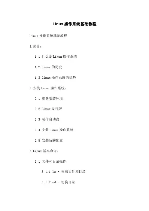
Linux操作系统基础教程Linux操作系统基础教程1.简介:1.1 什么是Linux操作系统1.2 Linux的历史1.3 Linux操作系统的优势2.安装Linux操作系统:2.1 准备安装环境2.2 Linux发行版2.3 制作启动盘2.4 安装Linux操作系统2.5 安装后的配置3.Linux基本命令:3.1 文件和目录操作:3.1.1 ls - 列出文件和目录3.1.2 cd - 切换目录3.1.3 mkdir - 创建目录3.1.4 cp - 复制文件和目录3.1.5 rm - 删除文件和目录3.1.6 mv - 移动文件和目录3.1.7 pwd - 显示当前目录3.2 文件内容查看和编辑:3.2.1 cat - 查看文件内容3.2.2 less - 分页查看文件内容3.2.3 vim - 文本编辑器的使用3.3 系统操作和管理:3.3.1 shutdown - 关机3.3.2 reboot - 重启3.3.3 ps - 查看进程信息3.3.4 top - 动态监控运行中的进程 3.3.5 su - 切换用户3.4 网络相关命令:3.4.1 ping - 测试网络连接3.4.2 ifconfig - 配置和显示网络接口信息3.4.3 netstat - 显示网络连接、路由表和接口统计4.Linux文件系统:4.1 文件系统简介4.2 Linux文件系统结构4.3 常见的文件系统类型4.4 文件权限和所有权4.5 文件系统相关命令5.Linux用户和权限管理:5.1 用户和组5.2 创建和管理用户5.3 用户组管理5.4 文件权限管理5.5 特殊权限和文件属性6.Shell脚本编程:6.1 Shell脚本语言简介6.2 运行Shell脚本6.3 Shell脚本的基本语法6.4 Shell脚本编程示例7.系统安全和日志管理:7.1 用户账户安全7.2 防火墙配置7.3 SELinux安全策略7.4 安全更新和漏洞修复7.5 日志管理8.常用服务器搭建:8.1 HTTP服务器搭建8.2 FTP服务器搭建8.3 SSH服务器搭建8.4 DNS服务器搭建8.5 邮件服务器搭建9.常见的故障处理:9.1 硬件故障处理9.2 网络故障处理9.3 系统崩溃和故障排查9.4 应用程序故障排查10.附件:附件1:Linux常用命令表附件2:Linux文件系统类型列表附件3:Shell脚本编程示例法律名词及注释:- GPL(General Public License):通用公共许可协议,是自由软件基金会(FSF)发布的一种自由软件协议。

说明linux操作系统的安装步骤和简单配置
方法。
Linux操作系统是一种非常流行的操作系统,包括基于Linux内核的Ubuntu、 Fedora和CentOS等操作系统。
下面就介绍一下Linux 操作系统安装和简单配置方法。
一、安装Linux
1、首先下载Linux系统,通常有ISO文件和USB启动盘安装,要根据个人情况来选择。
2、在BIOS中设置开机方式,一般有光驱可开机、硬盘可开机和启动盘可开机三种,找到与自己电脑相匹配的模式,设置后使之可以正常进入安装界面。
3、根据安装引导界面的提示,一步步配置系统的语言、时区、磁盘分区等,将参数设置完毕后系统即可正常安装完毕。
二、简单配置
1、给系统设置一个开机密码以保护系统,以免被恶意攻击,常见的系统有root、admin、administrator等,可以根据自己的情况设置。
2、添加新用户,可以给不同的用户设置不同的权限和登录环境,有助于管理用户和资源,使用useradd命令就可以添加新用户。
3、Linux支持常见的网络服务,但为了确保网络安全,可以使用iptables工具对防火墙进行策略设置,当未知IP发起连接时,可以让iptables来作出判断,阻止一些恶意攻击。
总之,以上就是安装和简单配置Linux操作系统的方法,具体的操作可以根据实际情况进行调整,以保证系统的安全性和高效性。

第1章Linux简介与安装1991年荷兰赫尔辛基大学一名大二学生林纳斯·托瓦兹(Linus B. Torvalds)编写了Linux系统,并将其放在互联网上。
经过这20年的发展,Linux系统已经扩展到各个领域,从拥有成千上万个CPU的超级计算机到只有几个芯片组成的单片机,随处可见Linux系统的身影。
正是因为Linux的流行,笔者特意编写了此书,让读者可以更好地学习Linux。
本章主要涉及的知识点如下。
❑介绍Linux系统、主要发行版及Linux系统的优势等内容。
❑简述Linux系统中的存储及目录结构。
❑介绍VMware Workstation软件和虚拟化在企业中的应用。
❑以VMware虚拟机安装Linux操作系统为例,讲解Linux系统的安装过程及安装过程中的建议等内容。
1.1 Linux系统简介通常所说的Linux操作系统,是对使用Linux内核的一类操作系统的统称,这些操作系统的主要结构包括:Linux内核、人机交互程序、应用程序等。
本节将简单介绍Linux 的用途和优势。
说明:Linux内核是操作系统的核心部分,主要负责管理进程、存储设备和网络接口等。
无论何种操作系统,内核都至关重要,其决定了操作系统的许多性能指标。
小知识:Linux隶属于GNU(GNU’s Not UNIX)计划,该计划的目标是建立一个自由的操作系统,即自由地使用、复制、修改、发布操作系统及其中的软件。
GNU计划还包括许多软件,例如文本编辑器GNU Emacs、GCC等。
GNU/Linux操作系统通常被简称为Linux,如果没有特殊说明,本书中的Linux即指GNU/Linux。
1.1.1 Linux能做什么Linux究竟能为我们做些什么呢?这是每个用户都关心的问题。
目前Linux系统的应用主要分为桌面环境和企业环境两个方面,本小节将从这两个方面简单介绍Linux系统的应用。
1.桌面环境对于家庭用户而言,Linux提供了比较方便的KDE和GNOME桌面环境。

中文chrony手册Chrony是一个开源的网络时间同步工具,它提供了精确的时间同步和时钟校准功能。
本手册将介绍Chrony的安装、配置和使用方法,帮助您快速上手并正确使用Chrony。
一、安装Chrony1. 在Linux系统中,可以使用包管理工具安装Chrony。
以Debian/Ubuntu系统为例,执行以下命令安装Chrony:sudo apt-get install chrony2. 安装完成后,Chrony服务将自动启动并开始同步时间。
二、配置Chrony1. 配置文件路径Chrony的配置文件位于/etc/chrony/chrony.conf。
您可以使用任何文本编辑器编辑该文件。
2. 服务器设置在配置文件中,您可以定义时间服务器来同步时间。
添加以下行到配置文件中:server time_server1server time_server2将time_server1和time_server2替换为您选择的时间服务器地址或主机名。
3. 允许本地网络访问如果您希望本地网络的其他计算机可以访问Chrony服务,请添加以下行到配置文件中:allow <local_network_ip>将<local_network_ip>替换为您的本地网络IP地址段。
4. 其他配置选项Chrony还提供了其他配置选项,您可以根据需要进行配置。
具体的配置选项说明可以参考Chrony官方文档。
三、使用Chrony1. 启动Chrony安装完成后,Chrony服务会自动启动。
您可以使用以下命令手动启动Chrony:sudo service chrony start2. 检查时间同步状态您可以使用以下命令检查Chrony当前的时间同步状态:chronyc tracking输出结果中的"Last offset"字段显示了最近一次时间同步的偏差。
3. 强制时间同步如果您需要立即同步时间,可以使用以下命令强制Chrony进行时间同步:sudo chronyd -q 'server time_server1 iburst'将time_server1替换为您选择的时间服务器地址或主机名。

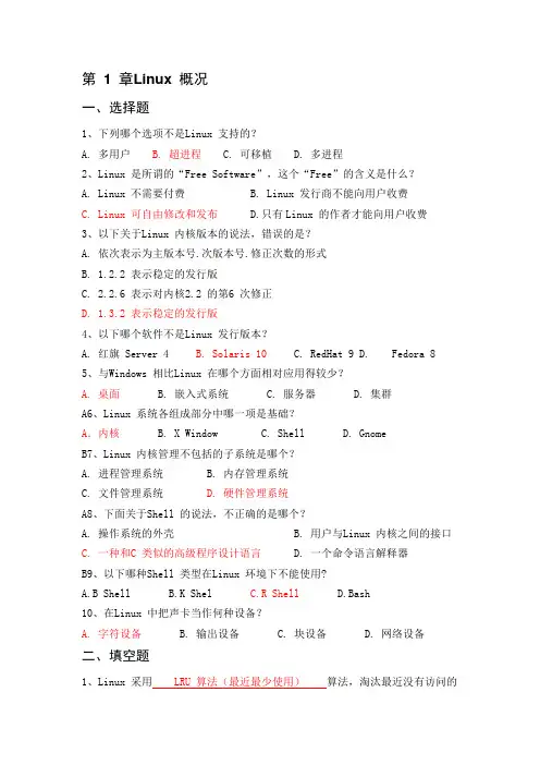
第 1 章Linux 概况一、选择题1、下列哪个选项不是Linux 支持的?A. 多用户B. 超进程C. 可移植D. 多进程2、Linux 是所谓的“Free Software”,这个“Free”的含义是什么?A. Linux 不需要付费B. Linux 发行商不能向用户收费C. Linux 可自由修改和发布D.只有Linux 的作者才能向用户收费3、以下关于Linux 内核版本的说法,错误的是?A. 依次表示为主版本号.次版本号.修正次数的形式B. 1.2.2 表示稳定的发行版C. 2.2.6 表示对内核2.2 的第6 次修正D. 1.3.2 表示稳定的发行版4、以下哪个软件不是Linux 发行版本?A. 红旗 Server 4B. Solaris 10C. RedHat 9D. Fedora 85、与Windows 相比Linux 在哪个方面相对应用得较少?A. 桌面B. 嵌入式系统C. 服务器D. 集群A6、Linux 系统各组成部分中哪一项是基础?A.内核 B. X Window C. Shell D. GnomeB7、Linux 内核管理不包括的子系统是哪个?A. 进程管理系统B. 内存管理系统C. 文件管理系统D. 硬件管理系统A8、下面关于Shell 的说法,不正确的是哪个?A. 操作系统的外壳B. 用户与Linux 内核之间的接口C. 一种和C 类似的高级程序设计语言D. 一个命令语言解释器B9、以下哪种Shell 类型在Linux 环境下不能使用?A.B ShellB.K ShelC.R ShellD.Bash10、在Linux 中把声卡当作何种设备?A. 字符设备B. 输出设备C. 块设备D. 网络设备二、填空题1、Linux 采用 LRU 算法(最近最少使用)算法,淘汰最近没有访问的物理页,从而空出内存空间以调入必须的程序段或数据。
2、之所以Linux 能支持多种文件系统的原因是,Linux 采用虚拟文件系统技术。
光驱安装或U盘充作光驱安装安装准备:①购买red hat 的安装光盘或或者下载镜像文件(后缀是.iso)②硬盘中至少留2个分区给安装系统用挂载点所用分区4G以上交换分区swap,250M左右比较合适③记录电脑中下列设备型号:鼠标、键盘、显卡、网卡、显示器网络设置用到的IP地址、子网掩码、默认网关、DNS名称服务器地址信息等安装过程:(1)启动服务器,按F2,进入bios设置:选择boot选项,boot:Boot option #1:如果是光驱安装,则设置光驱启动;如果是U盘安装,则设置USB启动(类似USB 2.0 USB Flash Drive 0.00)—>选择save选项,保存并退出;或者,如果光驱支持自启动,将直接出现下面的(2)Boot:linux text console=ttyS0,115200n1,回车(3)提示:是否测试安装CD的内容的完整性,选“Ok”开始测试安装CD,选“Skip”不测试安装CD(第一次安装当然要测试安装CD,选“Ok”后回车)安装过程中,可以对安装介质做检测,因检测时间慢,为提高效率,建议选择“Skip”来跳过(4)进入欢迎的界面:“Ok”(5)进入选择安装语言的界面:选择安装向导所用语(不是安装系统所用语),一般是English(6)安装方式:通过什么安装的或用来安装的那个linux在什么地方?Local CDROM本地光盘——如果是光盘的话,应该选第一个,光驱安装Hard drive 本地硬盘NFS Image 网上邻居映像文件FTP FTP服务器Http http服务器“Ok”(7)进入安装序列号界面:选择(*)Skip entering installation Number,“Ok”(8)进入授权认证界面:“Skip”(9)进入分区类型界面:注释:安装程序需要对您的硬盘进行分区.大多数用户使用默认的分区布局对就可以了。
你可以选择使用默认分区布局或创建您自己的分区布局;删除所选驱动器上的所有分区并创建默认分区布局;在所选驱动器上的空闲磁盘空间上创建默认分区布局;创建自定义的分区布局。
P/N: 1802031311019*1802031311019*AWK-3131A Series Quick Installation GuideMoxa AirWorksVersion 8.1, January 2021Technical Support Contact Information/support2021 Moxa Inc. All rights reserved.Table of ContentsOverview ............................................................................... - 3 -Hardware Setup .................................................................... - 3 -Package Checklist ............................................................... - 3 -Panel Layout of the AWK-3131A ........................................... - 4 -Mounting Dimensions .......................................................... - 5 -DIN-Rail Mounting .............................................................. - 5 -Wall Mounting (Optional) ..................................................... - 6 -Wiring Requirements ........................................................... - 7 -Read and Follow These Guidelines: ....................................... - 7 -Grounding the AWK-3131A .................................................. - 8 -Installations with Cable Extended Antennas for OutdoorApplications ................................................................. - 8 -Wiring the Redundant Power Inputs ...................................... - 9 -Wiring the Relay Contact ..................................................... - 9 -Wiring the Digital Inputs ..................................................... - 10 -Cable Holder Installation .................................................... - 10 -Communication Connections ............................................... - 10 -10/100BaseT(X) Ethernet Port Connection ...................... - 10 -1000BaseT Ethernet Port Connection .............................. - 11 -RS-232 Connection ...................................................... - 11 -LED Indicators .................................................................. - 12 -Specifications .................................................................... - 13 -Software Setup ................................................................... - 15 -How to Access the AWK ...................................................... - 15 -First-Time Quick Configuration ............................................ - 16 -Point-to-Multipoint Scenario (AP/Client Mode) ................. - 16 -Point-to-Point Scenario (Master/slave mode) ................... - 18 -OverviewThe AWK-3131A 3-in-1 industrial wireless access point meets the growing need for faster data transmission speeds and wider coverage by supporting IEEE 802.11n technology with a net data rate of up to 300 Mbps. The AWK-3131A combines two adjacent 20 MHz channels into a single 40 MHz channel to deliver a potent combination of greater reliability and more bandwidth. The two redundant DC power inputs increase the reliability of the power supply, and the AWK-3131A can be powered via PoE to make deployment easier. The AWK-3131A can operate on either the 2.4 or the 5 GHz band and is backwards-compatible with existing 802.11a/b/g deployments.Hardware SetupThis section covers the hardware setup for the AWK-3131A. Package ChecklistMoxa’s AWK-3131A is shipped with the following items. If any of these items is missing or damaged, please contact your customer service representative for assistance.• 1 AWK-3131A wireless AP/client• 2 2.4/5 GHz antennas: ANT-WDB-ARM-0202•DIN-rail kit• 2 plastic RJ45 protective caps•Cable holder with one screw•Quick installation guide (printed)•Warranty cardPanel Layout of the AWK-3131A1.Grounding screw (M5)2.Terminal block for PWR1,PWR2,relay, DI1, and DI23.Reset button4.System LEDs: PWR1, PWR2, PoE,FAULT, and STATE LEDs5.LEDs for signal strength6.WLAN LED7.Ethernet LED8.RS-232 console portN: 10/100/1000 BaseT(X) RJ45Port10.Antenna A11.Antenna B12.Model name13.Screw holes for wall-mounting kit14.DIN-rail mounting kitMounting DimensionsUnit = mmDIN-Rail MountingWhen shipped, the metal DIN-rail mounting kit is fixed to the back panel of the AWK-3131A. Mount the AWK-3131A on to a corrosion-free mounting rail that adheres to the EN 60715 standard.STEP 1: Insert the upper lip of the DIN-rail kit into the mounting rail. STEP 2:Press the AWK-3131A towards the mounting rail until it snaps intoplace.To remove the AWK-3131A from the DIN rail, do the following:STEP 1:Pull down the latch on theDIN-rail kit with a screwdriver.STEP 2 & 3:Slightly pull the AWK-3131Aforward and lift it up to remove itfrom the mounting rail.Wall Mounting (Optional)For some applications, it may be more convenient to mount theAWK-3131A to a wall, as illustrated below.STEP 1:Remove the aluminumDIN-rail attachment platefrom the AWK-3131A, andthen attach thewall-mounting plates withM3 screws, as shown in theadjacent diagrams.STEP 2:Mounting the AWK-3131A to a wall requires 3 screws.Use the AWK-3131A device, with wall-mounting platesattached, as a guide to mark the correct locations of the3 screws. The heads of the screws should be less than 6.0mm in diameter, and the shafts should be less than 3.5mm in diameter, as shown in the figure on the right.Do not drive the screws in all the way—leave a space of about 2 mm to allow room for sliding the wall-mounting panel between the wall and the screws.NOTE Test the screw head and shank size by inserting the screws into one of the keyhole shaped apertures of the wall-mounting platesbefore they are fixed to the wall.STEP 3:Once the screws are fixed into the wall,insert the four screw heads throughthe large opening of thekeyhole-shaped apertures, and thenslide the AWK-3131A downwards, asindicated to the right. Tighten thethree screws for added stability.WARNING• This equipment is intended to be used in a Restricted Access Location, such as a dedicated computer room where only authorized service personnel or users can gain access. Such personnel must be instructed about the fact that the metal chassis of the equipment is extremely hot and may cause burns. •Service personnel or users have to pay special attention and take special precautions before handling this equipment. •Only authorized, well-trained professionals should be allowed to access the restricted access location. Access should be controlled by the authority responsible for the location with lock and key or a security identity system. • External metal parts are hot!! Pay special attention or usespecial protection before handling the equipment.Wiring RequirementsRead and Follow These Guidelines:• Use separate paths to route wiring for power and devices. If powerwiring and device wiring paths must cross, make sure the wires are perpendicular at the crossing point.NOTE Do not run signal or communications wiring and power wiring in the same wire conduit. To avoid interference, wires with different signal characteristics should be routed separately.• You can use the type of signal transmitted through a wire todetermine which wires should be kept separate. The rule of thumb is that wiring that shares similar electrical characteristics can be bundled together.• Keep input wiring and output wiring separated.•For future reference, you should label the wiring used for all of your devices.Grounding the AWK-3131AGrounding and wire routing help limit the effects of noise due to electromagnetic interference (EMI). Run the ground connection from the ground screw to the grounding surface prior to connecting devices.Installations with Cable Extended Antennas for Outdoor ApplicationsIf an AWK device or its antenna is installed in an outdoor location, proper lightning protection is required to prevent direct lightning strikes to the AWK device. In order to prevent the effects of coupling currents from nearby lightning strikes, a lightning arrester should be installed as part of your antenna system. Ground the device, antenna, as well as the arrester properly to provide maximum outdoor protection for the device.Arrester Accessories•SA-NMNF-01: Surge arrester, N-type (male) to N-type (female) •SA-NFNF-01: Surge arrester, N-type (female) to N-type (female) Wiring the Redundant Power InputsThe top two pairs of contacts of the 10-contact terminal block connector on the AWK-3131A’s top panel are used for the AWK-3131A’s two DC inputs. Top and front views of the terminal block connector are shown below.STEP 1: Insert the negative/positive DC wires Array into the V-/V+ terminals.STEP 2: To keep the DC wires from pulling loose,use a small flat-blade screwdriver to tighten thewire-clamp screws on the front of the terminalblock connector.STEP 3: Insert the plastic terminal blockconnector prongs into the terminal blockreceptor, which is located on the AWK-3131A’stop panel.NOTE Input Terminal Block (CN1) is suitable for wire size range of 12-28 AWG (3.31-0.0804 mm²) and a torque value of 4.5 lb-in(0.51 Nm).Wiring the Relay ContactThe AWK-3131A has one relay output, which consists of the two contacts of the terminal block on the AWK-3131A’s top panel. Refer to the previous section for detailed instructions on how to connect the wires to the terminal block connector, and how to attach the terminal block connector to the terminal block receptor. These relay contacts are used to indicate user-configured events. The two wires attached to the Relay contacts form an open circuit when a user-configured event is triggered. If a user-configured event does not occur, the Relay circuit will be closed.Wiring the Digital InputsThe AWK-3131A has two sets of digital inputs—DI1 and DI2. Each DI comprises two contacts of the 10-pin terminal block connector on the AWK-3131A’s top panel. Refer to the “Wiring the Redundant Power Inputs” section for detailed instructions on how to connect the wires to theterminal block connector, and how to attach the terminal block connector to the terminal block receptor.Cable Holder InstallationAttach the cable holder to the bottom of the AWK-3131A to keep cabling neat and avoid accidents that result from untidy cables.STEP 1: Screw the cable holder onto the bottomof the AWK-3131A.STEP 2: After mounting the AWK-3131A and plugging in the LAN cable, tighten the cable along the device and wall.Communication Connections 10/100BaseT(X) Ethernet Port ConnectionThe 10/100BaseT(X) ports located on the AWK-3131A’s front panel are used to connect to Ethernet-enabled devices.Below we show pinouts for both MDI (NIC-type) ports and MDI-X (HUB/switch-type) ports. MDI Port Pinouts MDI-X Port Pinouts 8-pin RJ45PinSignal1 Tx+2 Tx-3 Rx+6 Rx- Pin Signal 1 Rx+ 2 Rx- 3 Tx+ 6 Tx-1000BaseT Ethernet Port Connection1000BaseT data is transmitted on differential TRD+/- signal pairs over copper wires.MDI/MDI-X Port Pinouts Pin Signal 1TRD(0)+ 2TRD(0)- 3TRD(1)+ 4TRD(2)+ 5TRD(2)- 6TRD(1)- 7TRD(3)+ 8 TRD(3)-RS-232 ConnectionThe AWK-3131A has one RS-232 (8-pin RJ45) console port located on the front panel. Use either an RJ45-to-DB9 or RJ45-to-DB25 cable to connect the AWK-3131A’s console port to your PC’s COM port. You may then use a console terminal program to access the AWK-3131A for console configuration.Console Pinouts for 10-pin or 8-pin RJ45 Ports 10-PinDescription 8-Pin 1– 2DSR1 3RTS 2 4GND 3 5TxD 4 6RxD 5 7DCD 6 8CTS 7 9DTR 8 10 –NOTE 1. The pin numbers for DB9 and DB25 male connectors, andhole numbers for DB9 and DB25 female connectors arelabeled on the connector strip. However, the numbers aretypically quite small, so you may need to use a magnifyingglass to see the numbers clearly.2. The pin numbers for both the 8-pin and 10-pin RJ45connectors (and ports) are typically not labeled on theconnector (or port). Refer to the pinout diagram above fordetails.LED IndicatorsThe front panel of the AWK-3131A contains several LED indicators. The function of each LED is described in the table below:LED Color State DescriptionPWR1 Green On Power is on (power input 1) Off Power is not being supplied.PWR2 Green On Power is on (power input 2) Off Power is not being supplied.PoE Amber On Power is being supplied via the PoE. Off Power is not being supplied via PoE.FAULT RedOnSystem is booting up, or a systemconfiguration error or relay event hasoccurred.Blinking(fast at0.5-secondintervals)Cannot get an IP address from theDHCP server.Blinking(slow at1-secondintervals)IP address conflictOff Error condition does not exist.STATE GreenOnSystem startup is complete and thesystem is in operation.Blinking(fast at0.5-secondintervals)AeroLink Protection is enabled and iscurrently in “Backup” state.Blinking(slow at1-secondintervals)Device has been located by WirelessSearch UtilityRed On System is booting upSIGNAL(5 LEDs) Green On Wi-Fi Signal Level (for client/slave/ client-router modes only)OffWLAN GreenOnWLAN function is in client/slave/client-router mode and has establisheda link with an AP.BlinkingWLAN data transmission is inclient/slave/client-router mode.OffWLAN is not in client/slave/client-router mode or has notestablished a link with an AP.AmberOn WLAN is in AP/master mode.BlinkingWLAN data transmission is in AP/mastermode.OffWLAN is not in use or not workingproperlyLED ColorState Description LANGreenOn LAN port’s 1000 Mbps link is active . Blinking Data is being transmitted at 1000 Mbps. Off LAN port’s 1000 Mbps link is inactive . Amber On LAN port’s 10/100 Mbps link is active. BlinkingData is being transmitted at 10/100 Mbps. Off LAN port’s 10/100 Mbps link is inactive.SpecificationsInput Current0.6 A @ 12 VDC; 0.15 A @ 48 VDC Input Voltage 12 to 48 VDC, redundant dual DC power inputsor 48 VDC Power-over-Ethernet (IEEE 802.3afcompliant)Power Consumption 7.2 WOperating Temperature Standard Models: -25 to 60°C (-13 to 140°F)Wide Temp. Models: -40 to 75°C (-40 to167°F)Storage Temperature -40 to 85°C (-40 to 185°F)NOTE For installation flexibility, either the A antenna (on the front panel) or the B antenna (on the top panel) may be selected foruse. Make sure the antenna connection matches the antennasconfigured in the AWK-3131A web interface.To protect the connectors and RF module, all radio ports shouldbe terminated by either an antenna or a terminator. We stronglyrecommend using resistive terminators for terminating theunused antenna ports.Software SetupThis section covers the software setup for the AWK-3131A.How to Access the AWKBefore installing the AWK device (AWK), make sure that all items in the package checklist are provided in the product box. You will also need access to a notebook computer or PC equipped with an Ethernet port. •Step 1: Select a suitable power source and plug in the AWK.The AWK can be powered by DC power ranging from 12 VDC to 48 VDC or by a PoE PSE via an Ethernet connection.•Step 2: Connect the AWK to the notebook or PC via the AWK’s LAN port.The LED indicator on the AWK’s LAN port will light up when aconnection is established.NOTE If you are using an Ethernet-to-USB adapter, follow the instructions in the user’s manual provided with the adapter.•Step 3: Set up the computer’s IP addressChoose an IP address for the computer that is on the same subnet as the AWK. Since the AWK’s default IP address is 192.168.127.253, and the subnet mask is 255.255.255.0, set the IP address to192.168.127.xxx, where xxx is a value between 1 and 252.•Step 4: Access the homepage of the AWK.Open your computer’s web browser and typehttp://192.168.127.253 in the address field to access the AWK’s homepage. Log in using the following default username andpassword:Default Username: adminDefault Password: moxaClick the Login button to access the homepage of the AWK device.First-Time Quick ConfigurationAfter successfully accessing the AWK, refer to the appropriate subsection below to quickly set up a wireless network.NOTE Ensure that there are no IP address conflicts when you configure more than one AWK on the same subnet.Point-to-Multipoint Scenario (AP/Client Mode)Configuring the AWK as an AP•Step 1: Set the operation mode of the AWK to AP mode.Go to Wireless LAN Setup→Operation Mode and select AP.NOTE The default operation mode for the AWK is AP.•Step 2: Set up your own SSID.Go to Wireless LAN Setup→WLAN→Basic WLAN Setup and click Edit to set the SSID.NOTE The default SSID is MOXA.•Step 3: Set the RF type and Channel for the AWK.Go to Wireless LAN Setup→WLAN→Basic WLAN Setup.We recommend that you choose the RF type 5 GHz for a relative clean medium with minimum interference.For the Channel setting, we recommend that you choose a channel other than the default channel to avoid interference.Click Submit to apply the changes, and restart the AWK in AP mode to complete the configuration process.Configuring the AWK as a Client•Step 1: Set the operation mode of the AWK to Client mode.Go to Wireless LAN Setup→Operation Mode, set the operation mode to Client, and then click Submit to apply the change.•Step 2: Link to an existing SSID.Go to Wireless LAN Setup→WLAN→Basic WLAN Setup and click Site Survey to select an existing SSID, or directly enter anexisting SSID in the text field.•Step 3: Set the RF type and Channel settings for the AWK.On the Wireless LAN Setup→WLAN→Basic WLAN Setup page, edit the RF type and Channel settings.Click Submit to apply the changes, and restart the AWK in client mode to complete the configuration process.Point-to-Point Scenario (Master/slave mode)Configuring the AWK as a Master•Step 1: Set the operation mode of the AWK to Master mode.Go to Wireless LAN Setup→Operation Mode, set the operation mode to Master, and then click Submit to apply the change. •Step 2: Set up your own SSID.Go to Wireless LAN Setup→WLAN→Basic WLAN Setup and click Edit to set the SSID.•Step 3: On the Wireless LAN Setup→WLAN→Basic WLAN Setup page edit the RF type and Channel settings.Click Submit to apply the changes, and restart the AWK in master mode to complete the configuration process.Configuring the AWK as a Slave•Step 1: Set the operation mode of the AWK to Slave mode.Go to Wireless LAN Setup→Operation Mode, set the operation mode to Slave, and then click Submit to apply the change.•Step 2: Link to an existing SSID.Go to Wireless LAN Setup→WLAN→Basic WLAN Setup and click Site Survey to select an existing SSID, or directly enter anexisting SSID in the text field.•Step 3: Set the RF type for the AWK.On the Wireless LAN Setup→WLAN→Basic WLAN Setup page edit the RF type setting.Click Submit to apply the changes, and restart the AWK in slavemode to complete the configuration process.。