
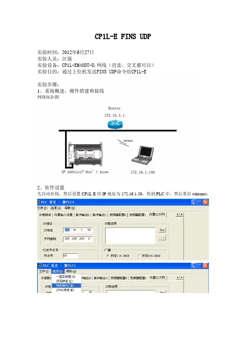
CP1L-E FINS UDP
- 格式:doc
- 大小:332.50 KB
- 文档页数:4
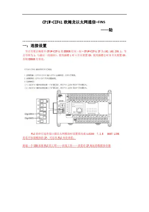
CP1W-CIF41欧姆龙以太网通信-FINS——陆一:连接设置节点号要正确要不CP1W-CIF41的ERROR灯闪(如·CP1W-CIF41 IP为192.168.250.1,节点号即为1,与最后一段相同)。
使用插槽1时4开关要置ON,使用插槽2时5开关要置ON,否则ERROR灯常亮。
PLC的串行选件端口插以太网模块时设置要改成115200 7,2,E HOST LINK若是不知道模块的IP,可以从PLC内存查看:新建一个USB连接PLC的工程——在线工作——查看存IP地址的数据寄存器例如放在选件板2的位置,则IP地址在D32300+155=D32455,D32456两个地址查看;注意地址D后面不要带M。
(右键点击空白栏,编辑即可输入并查看)连接方法1:知道模块IP后。
设置电脑IP与模块处于同一个网段即可。
FINS节点号即为模块IP的最后一个。
TIPS:最好将无线网卡禁用连接方法2:登陆http://192.168.250.1/c00.htm 注意:有时候模块要与电脑处于同一个网段才能连上(如模块192.168.250.1,电脑要为192.168.250.2)密码:ETHERNET修改完成以后点击传送,然后点击重启即可。
二:FINS指令:学习利用网络调试助手发送FINS命令对PLC进行操作,首先要学习FINS的通讯格式;1、FINS指令格式手册中的格式如下:举例说明:利用FINS/TCP 的方式读取PLC 的DM1通道的数据,格式解析如下: FINS 帧格式: ICF RS V GCT DNA DA1 DA2 S N A S A 1 SA2 SID CommandcodeTEXT固定 00固定 02目标网络号目标节点号目标单元号源网络号 源节点号 源单元号服务号,随便MR C SRC80 00 02 00 01 00 00C700 00 0101 820000000001MR 、SR 参见FINS 命令第5章;前面的ICF 、RSV 等为指定一些目标地址和源地址的网络号、节点号、单元号及其他固定的格式,后面关于Command code 以及TEXT 的内容,需要根据上位机实现什么的操作,填写不同的操作数据,就读取DM1通道的数据;DM 区的Memory area code 为82;读取存储区的Command code 为0101;返回时为C0写07也可,但返回也是0200表示本地网络,否则需创建路由表 00表示本地网络,否则需创建路由表下面利用网络调试助手进行测试:2、使用网络调试助手测试FINS/TCP利用上位发送FINS/TCP的格式如下:ETN21手册,编号W421,P203。

NB With CP1L-EM And CJ2M-CPU33 Through Ethernet(FINS/UDP)IntroductionThis article is related to the article NB HMI and Connecting Peripheral Devices and explains how connection can be established with a CP1L-EM and a CJ2M-CPU33 using Ethernet (FINS/UDP).Content1. Connecting Method2. Wiring diagram3. HMI Attribute settings4. PLC Attribute and PLC settings (PLC0)5. PLC Attribute and PLC settings (PLC1)6. HMI and PLC Network settings7. Example program1. Connecting MethodsEthernet (Fins/UDP)NB with a CP1L-EM and a CJ2M-CPU33 throughEthernet (FINS/UDP)2. Wiring diagramIn order to avoid malfunctions caused by interferences, use shielded cables.3. HMI Attribute settingsStart NB-designer, create a new program, drag and drop the NB (*TW001) and one Omron CP Series Ethernet (UDP Slave) and one Omron CJ Series Ethernet (UDP Slave) on the “Project Structure Window”.Double click on the NB in the “Project Structure Window” to open the HMI Attribute.Select the ‘HMI’ tab and set the IP address to (192.168.250.1) and the Subnet Mask to(255.255.255.0).4. PLC Attribute and PLC settings (PLC0) Double click on the CP(PLC0) in the “ProjectStructure Window” to open the PLC Attribute. Set the IP address to (192.168.250.2), Port (9600) and the Node ID to (2) in the PLC tab.Start CX-Programmer, create a newprogram and select a CP1L-EM. Openthe Settings properties. Select theBuild-in Ethernet tab.Set the IP address to(192.168.250.2), Sub-net Mask to(255.255.255.0) and the FINS NodeNo. to (2).5. PLC Attribute and PLC settings (PLC1)In NB-Designer double click on theCJ(PLC1) in the “Project StructureWindow” to open the PLC Attribute. Setthe IP address to (192.168.250.3), Port(9600) and the Node ID to (3) in thePLC tab.Start CX-Programmer, create a newprogram and select a CJ2M-CPU33 oradd a CJ2M-CPU33 to the existing file.Open the IO Table and Unit Setup.Select the Build-in Port/Inner Board anddouble click on the CJ2M-EIP (Built InEthernet/IP Port for CJ2M).Select the TCP/IP tab and set the IPaddress to (192.168.250.3), Sub-netMask to (255.255.255.0) and the FINSNode No. to (3).Set the ‘Rotary’ Node Address SettingSwitch at the front of the CJ2M-CPU33 to(3).6. HMI and PLC Network settingsIn NB-Designer double click on the NBin the “Project Structure Window” toopen the HMI Attribute.Select the ‘HMI’ tab and select‘Network Device Settings’.Add a Device, set Device Type to(HMI), Device No. (HMI0), IPAddress (192.168.250.1), Port Num:(9600), Comm Protocol (OMRON CPSeries Ethernet UDP) and Node ID to(1).Add a Device, set Device Type to(PLC), Device No. (PLC0), IPAddress (192.168.250.2), PortNum: (9600) and Node ID to (2).Add a second Master Device, setDevice Type to (HMI), Device No.(HMI0), IP Address (192.168.250.1),Port Num: (9600), Comm Protocol(OMRON CJ Series Ethernet UDP) andNode ID to (1).Add a Device, set Device Type to(PLC), Device No. (PLC1), IP Address(192.168.250.3), Port Num: (9600)and Node ID to (3).Save, compile and download the NB program and CX-Programmer settings to the units and restart all.7. Example programAttached file:Example program for a NB7W-TW01B with one CP1L-EM(PLC0) and one CJ2M-CPU33(PLC1) screen for Read/Write data to the CP1L/CJ2M through Ethernet (FINS/UDP) and a NB Setup screen to Adjust settings like Date, Time, Buzzer, Screen Saver, Brightness adjust and Calibrate screen.For the CP1L-EM and the CJ2M-CPU33 there is a CX-Programmer file for both PLC’s with the Communication settings for the Build-in Ethernet port.Reference:CP1L Operation Manual (Cat. No. W462)CJ2 Hardware User Manual (Cat. No. W472)Programmable Terminals Host Connection Manual (Cat. No. V108)Programmable Terminals NB-Designer Operation Manual (Cat. No. V106)Programmable Terminals Setup Manual (Cat. No. V107)Programmable Terminals Startup Guide Manual (Cat. No. V109)NB-series Manuals (included in NB-designer)Program versions: NB-Designer version 1.23 and CX-Programmer version 9.4。
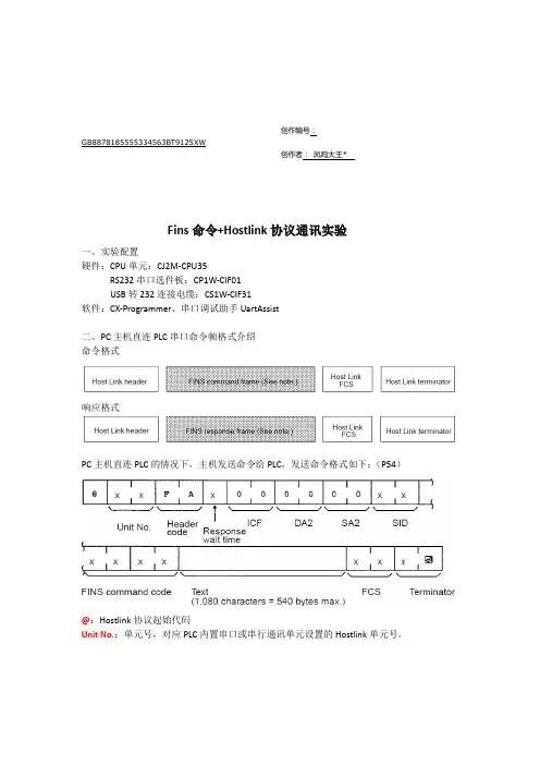
创作编号:GB8878185555334563BT9125XW创作者:凤呜大王*Fins命令+Hostlink协议通讯实验一、实验配置硬件:CPU单元:CJ2M-CPU35RS232串口选件板:CP1W-CIF01USB转232连接电缆:CS1W-CIF31软件:CX-Programmer、串口调试助手UartAssist二、PC主机直连PLC串口命令帧格式介绍命令格式响应格式PC主机直连PLC的情况下,主机发送命令给PLC,发送命令格式如下:(P54)@:Hostlink协议起始代码Unit No.:单元号,对应PLC内置串口或串行通讯单元设置的Hostlink单元号。
Header code:在PC主机直连PLC的情况下,头代码为FAResponse wait time:设置范围为0~F,单位为10ms,例如设置为2,则响应等待时间为20msICF、DA2、SA2:在PC主机直连PLC的情况下,固定为00。
SID:通常设置为00Fins command code:参考Fins通讯手册P125读命令:0101写命令:0102Text:具体操作内容,读写区域、读取起始地址、数据长度等内容存储区代码:(参考Fins通讯手册P137)DM(word):82W(bit):31W(word):B1CIO区(bit):30Tips:使用Fins指令最大可读取538个字节。
一条命令不能超过1114个字符。
三、串口通讯调试实例实例1——DM数据寄存器区读写实例;1、读取D0开始1个通道的值发送命令:@00FA 000000000 0101 82 000000 0001 7C *↙(回车键)返回命令码:@00FA004000000001010000123447*↙(回车键)2、读取D100开始的50个通道发送命令:@00FA00000000001018200640000327E*↙(回车键)3、写D200开始的2个通道发送命令:@00 FA 0 00000000 0102 82 00C8 00 0002 12345678 0F*↙(回车键) Header code:在PC主机直连PLC的情况下,头代码为FAResponse wait time:设置范围为0~FICF、DA2、SA2:在PC主机直连PLC的情况下,固定为00。

CP1LE内置以太网应用整理一:CP1LE内置以太网简介CP1LE得PLC得PLC内置有一个以太网口,这以太网口支持得应用如下:1:支持FINS指令,可以通过FINS指令与OMRON其她带有以太网口得PLC交换数据,相比CP1WCIF41只能做从站,CP1LE得可以进行读写。
2:支持Socket服务,CP1WCIF41不支持。
3:支持与PC自动IP连接,CIF41不支持。
二:各应用简单介绍。
一:支持与PC自动IP连接。
首先进行直接连接选择进入界面选择(本地连接(Direct connection target)。
2进行上面得操作后就可以到CXP进行以太网连接,不需要设置电脑得IP地址,PC就可以通过以太网与PLC进行在线。
二:两台CP1LE之间Fins指令交换数据。
在线完成后,设置两台PLC得IP地址与FINS节点号,如图:设置完成后,下载PLC,进行重启。
第一台PLC得设置第二台PLC得设置2、由于两台CP1LEM之间要通过FINS命令来进行数据交换,因此第二步就就是写FINS命令,这里以CMND指令做例子。
CMND指令介绍S FINS指令保存地址首字,D FINS响应保存首字,C FINS指令控制数据首字1508 0700C 发送字节个数(HEX)C+1 响应字节个数(HEX)C+2 0 0 目标网络号C+3 目标节点号目标单元号C+4 逻辑端口冲试次数C+5 响应监视时间D0 D1 存储到1号节点得 D202 D203 程序如图W10、02 为1时CMND指令执行,通信成功 D200中为0101,D201中显示0000,D202,D203中为2号节点 D0与D1得值。
1号站向2号站写FINS命令,0102 8200 6400 0002 0003 0004 向2号节点D100,D101中写#3 ,#4。
响应码:三: Socket服务1、打开UDPsocket端口1:A571、00UDP接收标志UDP发送Socket标志UDPsocket端口1打开标志注:本地端口号: 4096 远程IP地址 192、168、250、2 远程端口号:40962:发送Socket数据发送100个字节,即50个字,起始地址为D100。