
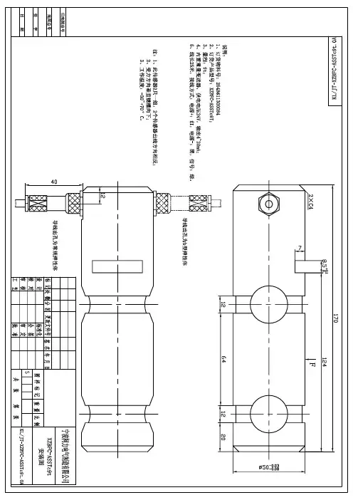
XZBFC-ASSTc9t(φ50)
- 格式:pdf
- 大小:119.79 KB
- 文档页数:1

Danfoss | August 2022 | AF423956205828en-000101Table of contentsX70 PLUGIN MOTOR CATALOG2Features ......................................................................................................................03Hydraulic schematic..................................................................................................03 ............................................................................................04Model code structure................................................................................................05 ....................................................................................................06Anti-cavitation valve .................................................................................................07Brake release port......................................................................................................08Motor installation drawings .....................................................................................09Shaft installation drawing ........................................................................................10Component selection guide.....................................................................................10 ...........................................................................1232 Speed axial piston motorX70 PLUGIN MOTOR CATALOG E-MOPI-CC004-E—May 2019 FeaturesDanfoss Medium Duty Piston Motors convert hydraulic energy supplied by the pump to mechanical energy. that requires continuous rotary motion at a remote location from the power source. Axial piston motors share the design advantages of piston pumps to provide long-lasting power in a lightweight, easily serviceable package. The table below provides an overview of features. For a complete list of options, refer to the Model Code section of a given motor displacement.• Field proven rotating group design • 2 speed option• Direct hydraulic operated control • Compact design• Brake release port to use with gear box • Planetary gear box option•Hot oil shuttle & anti-cavitation check valveHydraulic schematicrelease port42 Speed axial piston motorX70 PLUGIN MOTOR CATALOG E-MOPI-CC004-E—May 2019ParameterUnitModel 374AKXXXXXA (41 cc)Model 374AKXXXXXA (49 cc)Displacementcm 3/r [in 3/r]40.6 [2.48]49.2 [3.00]Maximum displacement cm 3/r [in 3/r] 32.0 to 40.6 [1.95 to 2.48]43.3 to 49.2 [2.64 to 3.00]Minimum displacement cm 3/r [in 3/r]7.4 [0.45], 10 [0.61], 13 [ 0.79],17 [1.037], 20.5 [1.25]16.30 [0.99], 20 [1.22], 22 [1.36], 26 [1.58], 29 [1.77], 32 [1.95]Maximum rated speed at maximum displacement rpm 35003500Maximum rated speed at minimum displacement rpm45004500Nominal pressure rating *bar [psi]350 [5076]310 [4500]Peak pressure rating **bar [psi]380 [5500]345 [5000]Output torque (theoretical)N-m / bar[lbf-in/1000 psi]0.65 [394]0.79 [480]Shift pressure range bar [psi]15 - 69 [220 to 1000]15 - 69 [220 to 1000]Maximum allowable case pressure bar [psi] 3.45 [50] 3.45 [50]Viscosity - Minimum cSt 6 cSt 6 cSt Viscosity - Optimum working range cSt 10-39 cSt 10-39 cSt Viscosity - Maximum cSt 2158 cSt2158 cStMaximum Fluid Temp-Inlet °C 105 degree celcius 105 degree celcius Minimum Fluid Operating Temp °C -30 degree celcius-30 degree celciusAmbient Temperature °C -30 to 80 degree celcius -30 to 80 degree celcius Weight lbs [kg]36 lbs [16.36 kgs]36 lbs [16.36 kgs]Cleanliness21/18/13 ISO/DIS 4406 (Class 9)21/18/13 ISO/DIS 4406 (Class 9)Notes:* Nominal pressure : Max. delta system pressure at which component fatigue does not occur. (Motor life estimated by bearing life** Peak pressure : Max. operating pressure which is permissible for a short duration of time [t<1 sec]52 Speed axial piston motorX70 PLUGIN MOTOR CATALOGE-MOPI-CC004-E—May 2019Model code structure1 2 3Code title X7M X70 variable displacement piston motor4 5Displacement4140.6 cm 3/r [2.48 in 3/r] 4949.2 cm 3/r [3.00 in 3/r]6Mounting ange A Plug-in mount7 8Output shaft0115 Tooth 16/32 Spline 0213 Tooth 16/32 Spline 03Taper 1:8 Per SAE J5019Main ports sizing A M27 X 2 Metric O-Ring port (A & B)B1.0625-12 UN-2B SAE o-ring port (A & B)10Port orientation1Radial ports 2Axial ports 11Motor control options ASingle input directly operated, external control supply, without pilot valve12 Control solenoids 0None13Supply ori ce0No ori ce10.53 [0.021] ori ce 14Valving 0No valves1Shuttle valve with loop ushing 2Blocked shuttle valves3Anti cavitation valve, unidirectional LH (CCW) Rotation4Anti cavitation valve, unidirectional RH (CW) Rotation15Flushing valve pressure setting 0None110.3-12.1 bar [150-175 PSI]211.4-13.1 bar [165-190 PSI]313.8-15.9 bar [200-230 PSI]415.2-17.2 bar [220-250 PSI]520.0-21.4 bar [290-310 PSI]16 17Minimum displacements077.37 cm 3/r [0.45 in 3/r]1010.65 cm 3/r [0.65 in 3/r]1111.47 cm 3/r [0.70 in 3/r]1313.44 cm 3/r [0.82 in 3/r]1616.30 cm 3/r [1.00 in 3/r] 1717.53 cm 3/r [1.07 in 3/r] 20 20.48 cm 3/r [1.25 in 3/r] 2222.45 cm 3/r [1.37 in 3/r] 2626.85 cm 3/r [1.64 in 3/r]3232.00 cm 3/r [1.95 in 3/r]18 19Maximum displacements 00Catalogue motor displacement 3333.1 cm 3/r [2.02 in 3/r]3535.6 cm 3/r [2.17 in 3/r]3838.0 cm 3/r [2.32 in 3/r]4343.3 cm 3/r [2.64 in 3/r]4545 cm 3/r [2.75 in 3/r]4747 cm 3/r [2.87 in 3/r]20Auxiliary mounting (rear)0No auxiliary mounting21Speed sensor option0No speed sensor1Speed sensor ready (plugged port)2With speed sensor22 Shaft seal option 0Standard nitrile23 24Special features00No special features25Paint 0Do not paint (Anti rust conservation oil)1Painted primer blue (Per spec 209-13CD)2Painted primer black (Per spec 209-13B)3Green per spec 209-13K 4Grey per spec 209-13P 5Red per spec 209-13V 6Y ellow per spec 209-13BF 7Bright yellow per spec 209-13CF26 27Identi cation00Standard 28Design codeA A213X7M454967328900340067006A9A41512528A1111A23780162 Speed axial piston motorX70 PLUGIN MOTOR CATALOG E-MOPI-CC004-E—May 2019The spring centered shuttle valve, located in the motor’s end cover, moves to connect the low pressure side of the loop to the low pressure relief valve. When back pressure gets high enough the low pressure relief valve, in the end keep the transmission cool. The low pressure relief valve in the motor’s end cover typically has a lower setting than the charge pressure relief valve in the charge pump. This is soto the reservoir.72 Speed axial piston motorX70 PLUGIN MOTOR CATALOG E-MOPI-CC004-E—May 2019 Anti cavitation valveAnti-cavitation valve is to prevent the cavitation of the motor during deceleration and spin down. These are the conditions motor suction which intern reduces pressure below partial pressure and arises cavitation. By introduction of the check valve in the circuit this condition will get eliminated as itmotor at desired speed.•For this option the high pressure port needs to be de ned upfront to get the correct motor rotation. Reversing the motor is not possible with this option.release port82 Speed axial piston motorX70 PLUGIN MOTOR CATALOG E-MOPI-CC004-E—May 2019release portBrake release portX70 series plugin motors are provided with a brake release port to allow the user to make an access to the brake-release feature of the machine gear box from the rear side of the motor.A brake release port is a simple passage provided on the a rear-facing 7/16 in. SAE O-ring boss port. Refer the release port. Applications using this brake release port require an O-ring to seal the passage against the gear box.While all motors will have the brake release port, not all gearboxes are compatible with this motor feature. Get in touch with your Danfoss representative in case of queries. The rated pressure for the brake release port on the motor housing is 250 bar (this does take into account the O-ring interface between the motor and gearbox). Check your gearbox for compatibility of this feature. If found as not Leave it plugged as shown in installation drawings.92 Speed axial piston motorX70 PLUGIN MOTOR CATALOG E-MOPI-CC004-E—May 2019Motor installation drawingsMating o-ring mininstalled inside Ø4.8 [0.19]Brake release port .4375 - 20 UNF - 2B Requires an o-ring: Viton 75 Durometer cross section -2.6 ± 0.07[0.103 ± 0.003]I.D. -126.6 ± 0.8[4.987 ± 0.035][3.39]29.2102 Speed axial piston motorX70 PLUGIN MOTOR CATALOGE-MOPI-CC004-E—May 2019Shaft installation drawingsØ 24.9[.98]Component selectionThe long service life of Danfoss hydrostatic transmissions is largely dependent on the proper selection and installation of the components necessary for transmission operation. The following components are necessary for transmission operation:• Variable displacement pump• Fixed or variable displacement motor • Reservoir • Filter• Charge pump inlet line• Pump and motor case drain lines • High pressure lines • Heat exchanger• Heat exchanger bypass valve •Reservoir return lineVariable displacement pumpDanfoss hydrostatic variable displacement pumps are anaxial piston design. They are equipped with standard SAE mounts, shafts and port connections.Fixed or variable displacement motorDanfoss hydrostatic motors are an axial piston design. They are equipped with standard SAE mounts, shafts and port connections.Sizing equationsFor sizing/selecting the right pump for your application please carryout following basic calculations.Commonly Used bar 3˚Cgallons (US) kgkgf/cm 2kW liters mm N-m N-m ˚F hp inch 3lb-in lb-ft lbsVolumetric Nv =Mechanical Nm =Total Nt = Nv x NmTo Co nvert cm 3 2in 3 P nQgpm m th lb-i n th in ˚lit lb p h 112 Speed axial piston motorX70 PLUGIN MOTOR CATALOG E-MOPI-CC004-E—May 2019 ReservoirThe reservoir is an important part of the hydrostatic transmission system. It should provide adequate oil storage and allow easy oil maintenance.The reservoir must hold enough oil to provide a continuous oil supply to the charge pump inlet. It must also have enough room for the hydraulic oil to expand as the system reservoir: One half (.5) minute times (X) the maximum the reservoir. Maintaining this oil volume will give the oil a minimum of thirty (30) seconds in the reservoir. This will allow any entrained air to escape and contamination to settle out of the oil.To allow for oil expansion, the reservoir’s total volume should be at least six tenths (.6) minute times (X) the The reservoir’s internal structure should cut down turbulence and prevent oil aeration.a di user to slow the incoming oil to 1 to 1.2 meters [3-4 line should also be positioned so that returning oil enters the reservoir below the liquid surface. This will help reduce aeration and foaming of the oil.immediately reenter- ing the pump.A sixty mesh screen placed across the suction chamber of the reservoir will act as a bubble separator. The screenof the reservoir where there may be a buildup of sediment. with a screen.should be designed to minimize the possibility of There should be a drain plug at the lowest point of the reservoir and it should also have a clean-out and inspection cover so the reservoir can be thoroughly cleaned after prolonged use. A vented reservoir should have a breather Sealed reservoirs must be used at altitudes above 2500 feet. and contraction.In both cases the caps must be designed to prevent water from entering the reservoir during bad weather or machine washing.A hydrostatic transmission with a well designed reservoir will run quieter, stay cleaner and last longer.Filter should not exceed ISO 18/15 per ISO 4406. Refer to Danfoss Hydraulic Fluid Recommendations.Pressure line – 5 micrometer Suction line = 3 OR 5 micrometer enough to prevent an excessive pressure drop between the reservoir and charge pump inlet. The pressure at the charge pump inlet port must not be less than 0,80 bar absolute [6 in. Hg.] at normal continuous operating temperatures.Charge pump inlet line The inlet line to the charge pump should be large enough to keep the pressure drop between the reservoir and section. Fittings will increase the pressure drop, so their velocities below 1,25 meters [4 feet] per second. Fluid and temperature compatibility must be considered when selecting the inlet line.Pump and motor case drain The case drain lines should be large enough to limit the pump and motor case pressures (Medium Duty to 2 bar [25 PSI]) at normal operating temperatures. Fluid and temperature compatibility must also be considered when selecting the case drain lines.High pressure lines The high pressure lines that connect the pump and motor must be able to withstand the pressures generated in the high pressure loop.Heat exchanger Use of a heat exchanger is dependent on the transmission’s duty cycle and on machine layout. The normal continuous motor cases should not exceed 80°C [180°F] for most exceed 107°C [225°F].The heat exchanger should be sized to dissipate 25% of the maximum input power available to the transmission. It must also be sized to prevent the case pressures in the pump and motor from getting too high. Medium duty case pressure up to 2 bar [25 psi], at normal operating temperatures, are acceptable.122 Speed axial piston motorX70 PLUGIN MOTOR CATALOG E-MOPI-CC004-E—May 2019Heat exchanger bypass valve The heat exchanger bypass valve is a pressure and/or temperature valve in parallel with the heat exchanger. Its purpose is to prevent case pressures from getting too high. The heat exchanger bypass valve opens when the oil is thick, especially during cold starts.Reservoir return line The same general requirements that apply to case drain lines apply to the reservoir return line.Bearing life estimation revolutions or time until a fatigue failure. Bearing load is calculated as a reaction which is derived from the moment created by the piston side load. Magnitude of the side load directly related to the speed and pressure at which a unit can be operated.Bearing life is a function of the side loads coming on the and cleanliness also a ects the life of bearing.If detail bearing life analysis is required, you can contact a Danfoss representative.Installation requirements The mounting orientation of pumps and motors is unrestricted provided the case drain of the pump and motor remain full. Position the case drain such that it assures an oil level at or above unit center line at start-up. The case drain be connected to the highest drain port on each of the units. This assures that the pump and motor cases remain full.The combined torque required to turn two or more pumps must not exceed the torque rating of the input drive shaft of the front piston pump. Installer to provide centering and a secure neutral for pump swashplate control shaft. An external support is recommended for all tandems.Open loop circuits Danfoss pumps and motors may be used in open loop circuits under certain operating conditions. Consult your Danfoss representative for details.Introduction system. Proper selection of oil assures satisfactory life and operation of system components. The purpose of this section is to provide readers with the knowledge required to Danfoss hydraulic components Viscosity and temperature most important characteristics to consider when choosing to maintain proper sealing at the operating temperatures of the hydraulic system.For viscosity requirements, see table operating temperatures of the hydraulic system. A high temperature.Lubricants used for hydraulic applications may contain shearing of VI improvers used in the formulations.Anti-wear hydraulic oils containing polymeric thickeners, viscosity index improvers (VII) are generally used for wide experience temporary and permanent viscosity loss during use in hydraulic system. Check the extent of viscosity loss (shear stability) to avoid hydraulic service below the recommended minimum viscosity. Oil with good shear stability is recommended for wide band temperature applications. Multi-grade engine oils, ATFs, UTTOs, etc., also contain VIIs, and viscosity loss will be encountered during use.Cleanliness important. More than 70% of all failures are caused by contamination. Danfoss recommends that the uid used in its hydraulic components be maintained per ISO 4406. Cleanliness level requirements vary with the hydraulic components. The cleanliness of a hydraulic system is dictated by the cleanliness requirements of the most stringent component in the system. in the table.OEM’s and distributors who use Danfoss hydraulic components in their hydraulic systems should provide these requirements in their designs.Contact Danfoss lter representative for ltration information.132 Speed axial piston motorX70 PLUGIN MOTOR CATALOG E-MOPI-CC004-E—May 2019 Fluid maintenance performance and reliability of the system. Maintaining and additive level is essential for excellent hydraulic system is recommended.Fluid selection Premium grade anti-wear (AW) petroleum based hydraulic uids will provide the best performance with Danfoss hydraulic components. Fluids that meet Danfoss Hydraulic Fluid Seeci cation E-FDGN-TB002-E are considered good quality anti-wear hydraulic uids. These uids pass Danfoss Vickers* 35VQ25A high pressure vane pump test (Eaton ATS-373 test procedure, ASTM D 6973).Automotive crank case oils with American Petroleum Institute (API) letter designation SF, SG, SH, SJ, or higher per SAE J 183 classes of oils are recommended for applications using Danfoss DG valves Automotive crankcase oils generally exhibit less shear stability compared to higher loss of viscosity during service life.Other mineral oil based lubricants commonly used in and universal tractor transmission oils (UTTO).biodegradability etc., are necessary for the application. Additional notes in the system must be considered. Viscosity limitations have to meet the most stringent component requirements.target one ISO code cleaner for each particle size, than that reading when the system is cold.For more details, refer to Danfoss Fluid Recommendation Document # 03-401-2010.Contact your representative if you have speci c questions about the uid requirements of Danfoss hydraulic components Viscosity & cleanliness recommendation Product Minimum*Optimum Maximum ISO Cleanliness Medium duty piston pumps and motors charged systems 6.0 cSt (45 SUS)10 – 39 cSt (60-180 SUS)2158 cSt (10000 SUS)21/18/13ote:N *Minimum viscosit y applies at intermittent condition of 10% of every minute. At viscosities lower than 70 sus, additional antiwear additives must be added to prevent premature wear. Please referto Danfoss document 03-401 for further details.Additional notes:• Fluids too thick to ow in cold weather start-ups will cause pump cavitation and possible damage. Motor cavitation is not a problem during cold start-ups, except for two speed motors. Thick oil can cause high case pressures which in turn cause shaft seal problems.• When choosing a hydraulic uid, all the components in the system must be considered and the optimum viscosity range adjusted accordingly. For example, when a medium duty piston pump is combined with a Disk Valve Motor the optimum viscosity range becomes100 - 180 SUS [20 - 39 cSt] and viscosity should never fall below 70 SUS [13 cSt].• If the natural color of the uid has become black it is possible that an overheating problem exists.• If the uid becomes milky, water contaminationmay be a problem.• Take uid level reading when the system is cold.• Contact your Danfoss representative if you havespeci c questions about the uid requirements of Danfoss hydraulic components.。
4WE10J73-3X/CG24N9K4/A12 4WE6J6X/SG24N9K4/V4WE6E6X/SG24N9K4/V 0820 024 602 4WE6C6X/EG24N9K4 4WE6J6X/EG24N9K4 4WE6JB6X/EG24N9K4 4WE6D6X/EG24N9K4 M-3SEW6U3X/420MG24N9K4/V4WE6D62/EG220N9K4 4WE6D6X/OFEG24N9K4 4WE6JA6X/EG24N9K44WE6J7X/HG24N9K4(或4WE6J6X/EG24N9K4) 4WE6HA6X/EG24N9K44WE10J3X/CG24N9K4 4WE6J6X/EG24N9K4 4WE6D6X/EG24N9K4(或4WE6C6X/EG24N9K4) 4WE10D3X/OFCG24N9K4 4WE6E6X/EG24N9K44WE6Y6X/EG24N9K4 4WE10EB3X/CG24N9K4 4WE6J6X/SG24N9K4/V4WE6E6X/SG24N9K4/V 4WE6D6X/EW230N9K4 4WE10J73-3X/CG24N9K4/A12 MK15G1X/V Z1S10P1-3X/V ZDB10P2-4X/200 Z2FS10-5-3X/V ZDB10P2-4X/315S10A1.2/ MK10G1X/V DBET-5X/315G24K4M PV7-17/10-14RE01MCO-16,00580381,A025 VT-VSPA2-1-1X/T1 VT-VSPA2-1-1X/T5 811405098 1834486001 VT11030-1X DBDS8G1X/25V DB20G2-5X/100 4WRPEH10C3B50L-2X/G24K0/FIM M-3SED6CK1X/350CG24N9K4 M-3SED10CK1X/350CG24N9K4 4WRPEH6C4B04L-2X/G24K0/FIM 4WRPEH6C3B04L-2X/G24K0/FIM 4WE10D73-3X/CG24N9K4/A12 4WE10J73-3X/CG24N9K4/A12 DR10DP2-4X/150YM 5610214530 577 608 022 024VDC 577 207 022 0 24VDC Z2FS 6-2-43/1QV P/N:MB02-1159-196 VT-VSPA1-1-1X VT-MSPA1-1-1X/V0/0 VT-VSPA1-2-1X/V0/0 VT-VRPA1-100-1X + 3HE/4TE VT-VSPA2-50-10/T1/ VT-VSPA2-50-1X/T1 2FRM16-3X/ A2F0125/61R-PBB05A4VS040DR/10R-PPB13NOO 5735040200 R103562520 4WE6J6X/EW230N9K4"4WE10J6X/CW230N9K4" VT-VSPA2-50-1X/T1 VT-VSPA2-50-1X/T54WMM6D5X/F 4WE6D6X/OFEG24N9K4/B10 A4VS0180DR/22R-PPB13NOOA10VSO1OODFR/31R-PPB13NOO DB10-2-5X/100VDBW20B25X/200S6EG24N9K4R10 PVV41-1X/122-036 RA15DDMC M-SR30 KE 05-1X/ DR10DP2-4X/75Y S30A3 SL10PA-1-4X AB32-10/3D-400 AB33-22/KD75 AB33-11/D4-40 AB31-07/750L2/R2 LC25B40E20=LC25B40E7XLC25A20E20==LC25A20E7X VT11006-1X 4WE10E3X/CG24N9K4 4WS2EM10-5X/75B11ET315KV 4WS2EM10-5X/75B11ET315K31EV 4WS2EM10-5X/10B11ET315EV 4WS2EM10-5X/10B11ET315K31EV 4WE6J62/EG24N9K4 512700001 512620005 A2FM32/61W-VAB010 MNR 9603892 S/N 6971699 VT3000 0811 104 113 0820 006 391, 0 821 300 990+1 824 210 243+1 834 484 096 4WE 6D62/EW230N9K4 4WE 6 GA61/EW230N9K4 4WE 6 J62/EW230N9K4 4WE 6H6X/EW230N9K4 4WE6D6X/EW230N9K4+Z4 4WE6H6X/EW230N9K4+Z44WE6E6X/EW230N9K4+Z4 MNR.R900909559 4WE 6D62/EW230N9K4 FD:486094WMM10D-10/E09-01030-00002 LB 17769 B11 001 506 MINR R9009095594WE6D62/EW230N9K4 FD48609 VT-VSPA1-1-11 MNR.R9000 33823 BF70-051DR16XA6-TF VT-VSPA2-1-11a/T1 VT-VSPD-1-1X/VO/O VT3002-20/32 VT3002-20/48 VT-VRPA2-1-1X/V0/T1 VT-VRPA2-1-1X/V0/T5 1827000003 821200005 821200003 821003003 1827231038 821302520 1827231016 ZIS6P1-2X DR6DP2-3X/150YM HED80P10/350 Z14 HED80P10/100 Z14 HED80P10/50 Z14HED80P10/100 Z14 3WE5A60/G24Z4 DRC3U-E5-53/100Y6EG24N9K4 SO176*00919655*Q25 3WE6A50/AG24NZ14 3DR3U 10 EP5 60/100Y6EG24N 9K4/00M *00919592* 4WE10E20/AW220-50NZ5L RSE2-063Z11/024S 25MPa MANNESMANN M 3 SEW6 C33/630M G24 Mg Z4 50 1203 M 3 SEW6 C30B/420MG24 DBOS6K 15/200.1125 DF-B10K3 A H25G(0.05MPa 2FRM5-30/102FRM6B36-3X/10QRV HED80A 1X/350Z14 4WMM6J5X/ A10VS028DR/31R-VDA12N00ZDR6DP2-4X/150Y Z2FS6-2-4X/ZQV HSZ16BB550-31/M01 DBDS20K18/315SL20PA M-3SED6CK13/350CG24N9K4 DVE10-1.1 M-SR8KE05 4WRZ32W6-520-7X/6EG24N9K4/D3M DB30-2-5X M-3SED10CK1X/350CG24N9K4/B22 M-SR15KE05-1X M-SR10KE05 M-SR10KE02 A4VSH250HSE/22R-PPB02N00N4WRSE6V10-31/G24KO/AIV-SO644 4WRSE6V50-3X/G24KO/AIV-280GFB17T2B33-02 M=10,Z=17 i=42.625 GFT17T3B88-01 A2FE45/61W-NZL100A4VG40EP2D/32R-NSC02F005D A2FW16/16W-VABD30 A4VG90EP2DT1/32R-NAFO2F+A4VG55EP2DT1/32R-NAF02F A4VG90EP2PT1/32R-NAF2F011DH-K+G2/011 AA6VM80EP2/03MVSC527HB A6VM80EZ4/63MVZB027BA6V8OEP2/63MBV2ZB026B GFT45W2/3B184-01 GFT17GFT17TW2-45-01GFT401=59.1 M-3SED6CK13/350CG24K4 DBDH6G1*31.5 0-31.5 VT10468-3X/BD VT-VSPA1K-1-1X A10VSO10DR/52R-PPA14N00 A10VSO140DR/31R-PPB12N00 LT07MKA-2X/100/02M 3WH6A5X 21305 71030 R9010170026 0510 900084WE6E62/EG24N9K4 4WE6C62/EG24N9K4 CDM1MP5/32/18/50A10/B1CGDMWW 4WE10EA-3X/CG24N9K4 4WE 10 E3X/CG24N9K4 4WEJ73-6X/EG24N9K4/A124WE 4 E20/EG 24N9K4 4WE 4 D20/EG 24N9K4 ZDR4DP2-1X/150YM ZDR6DA2-4X/150YM 4WE6J-6X/EG24N9K4 A10VS071DFR/31R-PPA12N00A10VS081DFR/3XR-PPA12N00 228/MP6/63/45/450/DMO1CL DBDS10P1X/200 HSZ06A601 3X/M00 830100390 830100372 P59335 3-2 TH6 P 70-10/M05 REF 08 350 576 9ERIE 0403300731 341 058 000 0 HED40A 16/350ZL 24 4WE10D33/CG24N9K4 4WE10J33/CG24N9K4 081WV10P1V1004WS024/00D0 3WE6A61/EG24N9Z54WE10D33/CG24N9K4 082 001 9980 082 002 7325 HED80A1X/350K14 0510 725 331 0510 625 319 4WE10D33/CG220N9K4/V HM12-1X/315bar 0510 765 3404WRPEH10C3B50L-2X/G24K0/FIM M-3SED6CK1X/350CG24N9K4 M-3SED10CK1X/350CG24N9K4 4WRPEH6C4B04L-2X/G24K0/FIM4WRPEH6C3B04L-2X/G24K0/FIM 4WE10D73-3X/CG24N9K4/A12 4WE10J73-3X/CG24N9K4/A12 DR10DP2-4X/150YM 4WE6D6X/OFEG24N9K44WE6JA6X/EG24N9K4 4WE6J7X/HG24N9K4(或4WE6J6X/EG24N9K4)4WE6HA6X/EG24N9K4 4WE10J3X/CG24N9K4 4WE6J6X/EG24N9K44WE6D6X/EG24N9K4(或4WE6C6X/EG24N9K4) 4WE10D3X/OFCG24N9K44WE6E6X/EG24N9K4 4WE6Y6X/EG24N9K4 DB20G2-5X/1004WE10EB3X/CG24N9K4 4WE6J6X/SG24N9K4/V 4WE6E6X/SG24N9K4/V4WE6D6X/EW230N9K4 4WE10J73-3X/CG24N9K4/A12 DBDS8G1X/25V4WE10E3X/CG24N9K4+Z4 DBEME10-5X/315YG24K31M 0515R15A7 IPK40SM31 0515R15A7 IPK80SM28 DBDS10G12/200 DV-12-01.1/0 4WE10E33/CG24N9K4R901017022 DC24V 4WE6D62/OFEG24N9K4B10 4WE10D3X/OFCG24N9K4SV30PA1-4X DR30-5-5X/200Y FD32PA2X/B06V(00513337 ZDB10VA2-4X/200V4WE10D3X/OFCG24N9K4+2*Z5L SMS20/M1/4-1000A DBDS10K-1X/315 DR20-5-5X/100Y 4WE 10D33/CG220N9K4/V MNR:R900944371 4WE 6D62/CG220N9K4/V MNR:R901008288 572.740.0220 (24V DC 4RREE 6 V16-22/G24K31 A1V 4RREE 6 E16-22/G24K31 A1V VT-MAC8-10/S1-PM4 MNR:R901082896 TYPE:ABZFV-ME5-1X/M-A MRN:R900229743 24VD VT11118-1X 4WE10D50/G24NZ44WE10D3X/CG24N9K4+Z4 Z2S6-3-6X/ SCEA-LAN CKGB-XFN 4WRZ16W6-150-7X/6EG24N9ETK4/M 4WRZ25W6-325-7X/6EG24N9ETK4/M 3DREP6A-2X/45EG24N9K4/M ZDC16P-2X/M DBEP6A06 FE40LB/670LZ4M FES40CA-3X/670LK4M+Z4+Z9 VT-VRPA1-51-1X A10VS0140DFR/31R-PPB12N00A10VS045DFR/31R-PPA12N00 A4VS0125DFR/30R-PPB13N004WEH16J7X/6EG24N9ES2K4+Z5L 4WRZ25E1-325-7X/6EG24N9EK4/D3M+Z44WRZ25W8-220-7X/6EG24N9TK4/D3M E-A4VSO 355 DR/30R PPB13N00R02K01A0NSP2 D633-315B R16K01A0NSP2 D633-419B D691-2705D-Q60FTAFCNEC2N 4WEH 16 HD7X/OF6EG24N9ETS2K4/V 4WEH 16HD7X/6EG24N9ETS2K4/V 4WE6 D62/OFEG24N9K4/V 4WE6 J62/EG24N9K4/V DRC-5-52/100Y/V DBW 10 B2-5X/315-6EG24N9K4V DBW 20 A2-5X/350-6EG24N9K4 V DBW 20 A2-5X/350-6EG24N9K4V 3DR 10 P5-6X/200Y/00V 3DR 16 P5-5X/200Y/00V M-3SEW 6 C3X/630MG24N9K4B12/V 4WE 10D3X/OFCG24N9K4/V DR 30 -5-5X/50YM/V DR 30 -5-5X/200YM/V 0820.032.992 0820.032.991 0822.034.202 Rexroth Z5L插头P/N 00057292 4WE6C62/EG24N94K4 DSHG-03-2B2-E-D24-12 4WE10D32/CG24K4, HED 80A 2X/350K14AS ZD B6 VP2-42/315, ZD R6DP2-43/210YM VT-SPD-1-2X/VO/0-0-1 VT3002-2X/48F VT-HNC100-1-23/W-08-P-0 VT-VSPA2-50-1X/T1 AB31-11/063-250 AB-20-09/MOSG1/4A3C AB-20-24/GE10SR1/4EDA3C AB-E21-14 AB-31-11/063-250 A10VS028DR/31L-PPA12K01+AZPF-1X-005LRR20MB AB-E21-14 VT-VSPA1-1-1X/ VT-VSPA1K-1-1X/ VT-PVQ1-1X/0 VT-PVQ1-1X/1 VT-PVQ1-1X/2 VT-HNC100-1-22A/W-08-P-0 R900958999 A305 RR06090 HEDE10A1-1X/250K41G24V+00779509 4WE6H61/EG24N9K4 00874512 A10VSO71DFR1/31R-PPA12N004WE6D6X/OFEG24N9K4 4WRTE1OV1-100L-41/6EG24ETK31/A5M VT-VSPA2-50-10/T5 P55556-3 EA4VS0125DR/30R-PPB13N00 Z4S16-2X 2FRM16-3X/160L P-032110-0000/06W23 SCE-24-K24 PPF SR102 MAKER:"TOWIMOR"S.A. 87-100 TORUN,UI.ATAROTORUNSKA 5-POLAND MODLE:CD 16HD+PK 78 3B HYDRAULIC MOTOR:MRD 700(REXROTH A1OV028DR/31R-PSC12NOOA1OVS028DFLR/31RPPA12NOO A10VSO100DFLR/31R-PPA12N00A10VSO100DR/31R-PPA12N00 A10VSO100DR/31R-PPA12N00 A4VSO250HD1GB/22R-PPB13NOO-S086 A4VSO250HD1GB/22R-PPB13NOO-S086A4VSO40LR2G/10R-PPB13K25-S086+A10V028DFR+A10V028DFR A4VSO125LR2G/22R-PPB13NOO-S086 MK15G1X/V Z1S10P1-3X/V ZDB10P2-4X/200Z2FS10-5-3X/V ZDB10P2-4X/315 S10A1.0 MK10G1X/V DBET-5X/315G24K4M4WE 6 C6X/EG24N9K4 4WE 6 J6X/EG24N9K4 4WE 6 JB6X/EG24N9K4 4WE 6D6X/EG24N9K4 M-3 SEW 6 U3X/420 M G24 N9K4/P 08213027134WE10C33/0FCG24N9K4, MNR:R9005009254WE10Y33/CG24N9K4,MNR:R900595531 4WS2EM10-51/20B11XHET315K31EV-100 4WS2EM10-51/75B11XHT315K31EV 0811-402-107 VT3002-2X/32D VT3002-2X/48F VT3002-2X/64G VT3006-36A 1824210223 DC24V 820024126 PV7-1X/10-14RE01MC0-16 VT11013-12 VT5006-S16 VT11030-12A 4WE10J-30/AG244WE10J3X/CG24N9K4 ZDR10DP2-40/21YM ZDR10DP2-5X/210YM Z2S10-10Z2S10-1-3X Z2FS10-20 Z2FS10-5-3X/V VT11118-1X/ VT3000-3X/ VT5006-1XVT3002-2X/32D 4WE10E33/CG24N9K4 4WE6J62/EG24N9K44WE6D6X/EW230N9K4+Z4 VT5041-2X/1-0C VSPA2 4WE6J6X/EG24N9K4+Z5L 4WE6V6X/EG24N9K4+Z5L 4WE6JB6X/EG24N9K4+Z5L VT-VRPA1-52-10 VT3006-36 VT-VSPA2-50-1X/T5 VT-VRPA1-52-1X VT2000-5X VT3006-3X VT5006-1X VT-RK2-3X VT-PVAR2-1X/0 VT-PVAR2-1X/1 VT-PVAR2-1X/2R900212093, W-3SEW C36/420M C25N922 31047981 R900212093, W-3SEWC36/420M C25N922 31046150 A10VSO28DR/31R-PPA12NOO PVR 24F/11-RE 95022/05.02 MANNESMANN REXROTH *00524932* LT05 MKA -12/100JLT05MKA-3X/100/02M 02M S06 0052301" MANNESMANN REXROTH *00428999* P15 LT06-A06-30/200B80/02M 242 R156, 0050618" 1PF2G2-4X016RC20MB 0510 625 022 4WE10E33/CG24N9K4 DBDS 10 G1X/100 AB21-20/G 1/2-400 LG6S-G-2X VT5003-41/R5E 736134 T0821 100 013, 1-16BAR AB31-01 0821 100 013, 0.1-1.6MPa HED8OA2X/100 Z14 AB31-05/0370Z AB20-11/K1 G1/4 3WE6B6X/EG24N9K4+Z4 4WE6D6X/EG110N9K4 4WE10D3X/CW230N9K4 SL20GA1-4X 2FRM 5-3X/1.2QA10VSO140DR/31R PPB12N00 4WE10E33/CG24N9K44WE6D60/BG24NXDZ2/V\GH45-2M.N M-3SE6U66/420LG24NXDZ2/V\GH45W-2M 0811 404 405 DBW20BG2-44/315-6AG12NDAV/12 4WE6J62/EG24N9K44WE6E62/EG24N9K4 DAW20B1-55/100-17/6EG24N9K44WE6Y62/EG24N9K4/B08 DBEM20-51/200XYG24NK4M-14WE6J60/SG24N9K4/B10V 4WE6J6X/EG24N9K4+Z5L 4WE6V6X/EG24N9K4+Z5L 4WE6JB6X/EG24N9K4+Z5L 1837.001.227 0811.402.004 0811.403.002 0810.092.100 MN1H-12-0-1-FR-S LR-1/4”-S-B A4VG90EP2DM1/32R-NZF02F001D 4WRPEH10C 4B100L 2x/G24 KO/A1M 1817005891 4WP10D3X/OFCG24N9K44WE6D6X/EG24N9K4/V,MNR:R900564105 0811 404 003+0811 405 120+1834 416 001 0811 401 224 4WRKE25E350L-3X/6EG24K31/A1D3M LC25AO5D-7X/LC40A20E7X/ LC50DB40E7X/ LFA25WEA-7X/ LFA40D-7X/ LFA50DR-7X/075 M-SR50DR-7X/075 M-SR30KE05-1X M-SR52KE05-1X A10VS045DR/31R-PPA12N00 DBDS30K1X/200' A11VL0260DRG/11R-NPD12NOOV A10VSO140DR/31R-PPB12N00 HED10A4X/350L24 DBW20A2-5X/315-6EG24N9K4 HM100-250-B-M20*1.5-FF DB30-2-5X/315 S15A1.0 LFA40RF-7X ZDC25P-2X/XM 4WRZE25W8-325-7X/6EG24N9EK31/F1D3M SL30PA1-4X DBD20K-1X/315 M-SR20KE02-1X4WE10C3X/CG24N9K4 LC40DR40E-7X LFA40DB2-7X/210 4WRZE32W8-520-7X/6EG24N9EK31/F1D3M LC40A05E-7X FD32PA2X/B06V4WEH16J7X/6EG24N9ETK4 Z2S16-2-5X Z2FS16-3X/S24WEH25J7X/6EG24N9ETK4 Z2S22-2-5X Z2FS22-3X/S2 D2773A3025 D2153B6012 RZGD-A-033/21031 A2FE90/61W-VAL100 OMM32 151G0033 HED80A12/200K14HED80A12/350K14 TYP:FMA-2N-MB/206 PD20/MATR L/1 20kg/cmb G1R1 1450 DZ20-2-5X/100 A2FE90/61W-VAL10 4WRZE16E150-70/6EG24N9ETK31/A1D3MA10VS071DFR/31R-PPA12N00 H06SDV2 PTB125bar A500bar CMZ-050TB EDS344-2-016-000 TVPE:ARV-VUU GE36-4-A443 24VDC 26W KDG4V-5-2C50-N-E-MV-H7-30 1E15P6-50S 2FRE16.4X/160LB A2FO-250/60RPB05 QAE-E6/10D-BU Z2S22-40 ETS1701-100-000 2103-018,00HD G1/4 S100-AC-AC-0100(Ф2mm,1m)4WRZ-25E3-325-50/6A24NETZ4/D3M DRV-1-01 500PSI A10VS0 28 DR\30 R-PPA 12 DV00/ CV-06G-05/20 WD-G02-B2-D2-N VT-VSPA2-50-10/T5FD16FA21/B03V DB1010-5X/200 ; NHT301-3C-1CS4Y2 RFB-400X20-Y LXZ-250X80-YY GE2 G3/4''Z2S10-3-34 ; Z2FS10-7-33/V ZDB10VP-2-4X/200 ; Z1S10P-1 ;HE4524S16RPSBLS HH6220C16RTSBR 220VAC QUQ2-20X1.0 CYL1MP5/400/160 CYLMP5/250/140 CY81MP5/50/28 CYA1MP5/5028 R900561278 R900561290;R900052392; D663-4007/L03HABD6VSX2-A D663-4307/P02JONF6VSX2-AD661-4033P80HAAF6VSX2-A D661-4651/G35JOAA6VSX2HA D661-4636/G60KOAA5VSX2HA S/N 967 62181 03679 8597 PAT NO 0513870220 CODE 0513R18C3VPV164SM21H2B01 J761-003, TYPE:S63JOGA4VPLD3DW20BVZP40XB510 XA,02-365591, 220VDC,30W. 072-559ATYPE:S15POFA4VBL 4WE6D62/EG220N9K4/V SV4-20(1557-80/40-10-S451 ASSY NO.3025217 210Bar 4WE10D33/OFCG220N9K4/V 220VDC 35W. NXR:R901025073 3WE10A33/CG220N9K4/V 220VDC 35W NXR:R9010836554WE6D60/BG24NXDZ2/V\GH45-2M.N M-3SE6U66/420LG24NXDZ2/V\GH45W-2M DHA-0631/2/A/PA-M24DC\ DPHA2631/2/D/PA-M24DC\QA-24DC DPHA2713/D/PA-M24DC\QA-24DC DPHA1631/2/D/PA-M24DC\QA-24DC A10VSO140DR/31RPPB12N00 4WE10E33/CG24N9K4 PVR 24F/11-RE 95022/05.02 LT05MKA-3X/100/02M LT06-A06-30/200B80/02M 4WE 6 D6X/EG24N9K4 4WE 6D6X/OFEG24N9K4 4WE 10 D3X/CG24N9K4 DBET-5X/315G24K4V-21 M-3SED 10 UK1X/350CG24N9K4 M-3SED 6 UK1X/350CG24N9K4 4WE 10 U12-3X/CG24N9K44WE 10 C3X/CG24N9K4 3WE 10 A73-3X/CG24N9K4/A12 4WE 10 D73-3X/CG24N9K4/A12 4WE 6 Y6X/EG24N9K4 4WE 6 E6X/EG24N9K4 4WE 6H6X/EG24N9K4 HBD 8 OA-2X/350K145 DR 10 DP2-4X/75YM 3WE 6A6X/EG24N9K4 4WE 6 C6X/EG24N9K4 4WE 6 U12-6X/EG24N9K4 3WE 6 A73-6X/EG24N9K4/A12 M-3SED 6 CK1X/350CG24N9K4 HBD 8 OA-1X/100Z15L24KS VT-2000-5X VT-3002-2X/32D HM12-1X/315(4-20MA 4WE6J6X/EG24N9K4A10VS028DRF1/31R-PPA12N00 A10VS028DRF1/31R-PPA12N00 M-3SED6CK13/35OCG24N9K4/V M-SR8KE05-1X M-SR10KE05-1X M-SR20KE05-1X DB10-2-5X/315X ZDR6DP2-4X/150YM Z2FS6-2-4X/2Q LFA16E-7X/CA10DQMG24F LFA25E-7X/CA10DQMG24F 4WE6D6X/0FEG24N9K4MCR10D940L60Z-32/B7M DBET-52/50G24K4M M-3SED6CK13/35OCG24N9K44WE6D6X/EG110N9K4/V+Z5L 4WE6D6X/EG110N9K4/V+Z4HA4VSO250HD1G+HA4VSO250LR3G HA4VSO250HD3G+HA4VSO250LR3GDB10-3-5X/315 DBDS20K1X/315 DR10-4-5X/200YM DR15G-4-5X/200YMZDR10DP-2-5X/150YM Z2FS10-5-3X/V 4WE6D6X/EG24N9K4 M-3SEW10U1X/420MG24N9K4 4WRAE10W1-60-2X/G24K31/F1V 4WMM10E3X/F H-4WMM22T-7X/F Z2FS22-3X/S2 SL10PA1-4X SL20PA1-4X/ A10VS071DR/31R-PPA12N00 A4VSO180DR/30R-PPB13NOO LC25A10E-7X LFA25WEA-7X/F10A12 FD25PA2X/B04V DBW20B-1-5X/315-6EG24N9K4 4WS2EM10-45/75B 3T 315K8CV-94 DBDS3OK1X/25 DBAW3OAH3N1X/315-6EG24N9K4 Z2DB10VD3-4X/315 DBDA10P1X/25 3DR10P5-6X/200V/00M DBDS30K1X/25 DBAW40AH3N1X/315-6EG24N9K4 3DR16P5-5X/250Y/00M 811402030 8114020310811405145+2910151166 DR20-5-4X/100YM DR20-5-4X/200YM DBDS30K1X/24 DR10K5-3X/100YM M-SR8KE05-1X/ YC-610-2-B-0-K VT5008, S16 R1 #4 VT12350 32/0, S16 R1 #4 4WRE 10 E64-14/24K4/M, S16 R1 #4 AB32-10/6D380,00985571AB31-04/0280, R9000030642 FSA254-1.1/T/12 AB31-14/3-1A2A3A AF6EP4X/Y160V4WE6J6X/EG24N9K4 4WE10J3X/CG24N9K4 4WRZ10W1-85-5X/6A24NETZ4/D3M4WRZ10W8-85-7X/6EG24N9ETK4/D3M+Z4,VT-VSPA2-50-1X/T5A7V107DR1RPFOO A7VO107DR/63R-NPB01 4WRSEH 6V50LD 30/G24 K0/A1V HED80H1X/200K/4S VT-VSPA2-1-1X/T1 ZDB6VP2-4X/200 4WRA10W1-30-2X/G24K4 A10VSO140DR/31R-PPB12N00 DBW10B1-5X/315-6EG24NK4DBW20B2-5X/315-6EG24NK4 820402101 0811 4051 47 0811 4050 634WE6J6X/EG24N9K4 4WE6E6X/EG24N9K4 4WS2EM16-10/150 B2T 140Z8AS014WS2EM16-2X/150B12T210K8EV+Z8 VT-VRPA1-52-10 VT3006-36 VT-VSPA2-50-1X/T5 VT-VRPA1-52-1X VT-PVAR2-1X/0 VT-PVAR2-1X/1 VT-PVAR2-1X/2 VT-VSPA2-50-1X/T5 VT-VSPA2-1-1X/T5 VT-VRPA2-2-1X/VO/T1 VT3002-2X/32DVT3002-2X/48F VT-10-468-32FORX CODE:0504480 VT3014-3X VT3002-2X/32D VT5010-2X/R1E VT5010-2X/R5E VT3002-2X/48F VT3002-2X/48F VT-11077-2X VT-VRPA2 VRPA2-1 VT3002-2X/48F VT5008, S16 R1 #4 VT12350 32/0, S16 R1 #4 VT-VRPA1-52-10 VT-3006-36 VT-VSPA2-50-1X/T5 VT-VRPA1-52-1X VT11118-10 VT-MRPA2-1-11A VT3006-3X VT5010S 2X/R5+VT3002 VT3014S 3X+VT3002 VT-VRPA1-52-10 VT3006-36 VT-VSPA2-50-1X/T5 VT-VRPA1-52-1X VT2000-5XVT5006-1X VT-RK2-3X VT-PVAR2-1X/0 VT-PVAR2-1X/1 VT-PVAR2-1X/2 VT-VSPA2-50-1X/T5 VT-3002-2X/32D VT-VSPA2-1-1X/T1 VT-VSPA2-1-1X/T5 VT-VSPA2-50-1X/T1 VT-VSPA2-50-1X/T5 VT3002-2X/32D VT-VSPA1-1-1X/ VT-PVQ1-1X/0 VT-HNC100-1-22A/W-08-P-0 R900958999 A305 RR06090 BOSCH REXROTH SPARE PARTS MODEL NO. ZDR10DP1-5X/150YM ZDR10DA2-5X/150Y ZDR10DA1-5X/75Y ZDR10DA1-5X/25Y ZDC10P2X/XM ZDB6VP2-4X/315V CORE ZDB6VB2-4X/100 ZDB6VB1-4X/200V ZDB10VP3-4X/100VZDB10VP2-4X/100V ZDB10VB2-4X/50V ZDB10VA2-4X/100V ZDB10VA1-4X/315 ZBE08-05 ZBE 02 PLUG CONNECT. BINDER S714 Z4WEH22E63-5X/6EW110N9ETS2K4/B10D3 Z2S4A1-1X/ Z2FS22-3X/S2 CORE Z2FS10-5-3X/V SO30 Z2DB6VC2-4X/100V Z2DB22VD2-2X/50 Z2DB22VD2-2X/200V Z2DB10VD3-4X/315V Z2DB10VD2-4X/200SO30 Z2DB10VD2-4X/200 C Z1S6F1-3X/V Z1S10T2-3X/V Z1S10D2-3X/V ZSF80F0-1-1X/M/01 SO1 ZDZ6DP2-4X/210YM ZDRK6VP5-1X/100YMV ZDRE6VP1-1X/210MG24K4M ZDR6DP3-4X/25YM ZDR6DA3-4X/75Y ZDR4DP2-1X/150YM ZDR4DB2-1X/150YM ZDR10VP5-3X/200YM ZDR10VP5-3X/100YM ZDR10VB5-3X/200Y ZDR10VA5-3X/100YM ZDR10DP7-5X/75YM ZDR10DB2-5X/75YM ZDR10DA7-5X/75YM ZDR10DA2-5X/210Y ZDC16P2X/M ZDBK6VP3-1X/210V ZDBEE6VP2-1X/100G24K31M ZDB6VA2-4X/200 ZDB4DP2-1X/200V ZDB10VB2-4X/50V ZDB10VA2-4X/315V Z4WEH16E63-5X/6EG24N9ETK4QMAG24 Z4WE6E68-3X/EG24N9K4 Z4WE6E63-3X/EG24N9K4 Z4(A PLUG C Z2FSK6-2-1X/2QV Z2FS6A7-4X/2QV Z2FS6-7-4X/2QV Z2FS16-3X/S2V Z2FS10B7-3X/SV Z2FS10A5-3X/SV Z2FS10A3-3X/SV Z2DBK6VD2-1X/100V Z2DBK10VD2-1X/100V Z2DB6VD2-4X/200V Z2DB6VD2-4X/100VZ2DB6VC2-4X/200 SO37 Z2DB10VC2-4X/100V Z1S6P1-3X/VW4 Z1S6D3-3X/V ZSF63F1-1-1X/M/01 ZSF40FO-1-1X/M/01 SO1 ZDRK10VP5-1X/100YMVZDREE10VP2-1X/200XLMG24NK31M ZDRE6VP2-1X/210MG24K4M ZDRE10VP1-1X/315YMG24K4M ZDR6DP3-4X/75YMZDR6DA2-4X/150YM ZDR10VB5-3X/200YM ZDR10VB4-3X/50YM ZDR10VA4-3X/100Y ZDR10DP3-5X/150YM ZDR10DB2-5X/150YM ZDR10DA2-5X/150YM ZDC25P-2X/XM ZDC25P-2X/M ZDC16P2X/M ZDB6VP2-4X/100 ZDB6VB2-4X/50 ZDB6VB2-4X/200V ZDB6VA2-4X/100 ZDB10VP2-4X/315 ZDB10VP2-4X/200V CORE ZDB10VB1-4X/200V Z4WEH10E63-4X/6EG24N9ETK4/B10D3VZ4WEH10E63-4X/6EG24N9ETK4 Z4S10-3X/ Z2S16A2-5X/ Z2S16A1-5X/SO40Z2FS6B7-4X/2QV Z2FS6A2-4X/1QV Z2FS6-3-4X/2Q Z2DBK6VC2-1X/100VZ2DB6VD2-4X/315V Z2DB22VD3-2X/315 Z2DB22VD2-2X/200 Z2DB16VD3-2X/100 Z2DB10VD2-4X/200 Z1S6C3-3X/V Z1S22P1-1X/V Z1S16T3-1X/V Z1S10T3-3X/V Z1S10C3-3X/V Z15L110 Z14 GDM 3011 PLUG ZDR10DA2-5X/75YMZDC25P-2X/XM ZDC25P-2X/M ZDC16P2X/XV ZDC10P2X/M ZDBK6VP1-1X/210 ZDB6VP2-4X/200 ZDB10VP2-4X/315 CORE ZDB10VB2-4X/315V ZDB10VB2-4X/200 ZDB10VA2-4X/100 CORE ZDB10VA1-4X/50V Z8 PLUG FOR 4WRS6-21Z4WEH10E63-4X/6EG205N9ETK4 Z4WE6E137-3X/EG24N9K4 Z2SRK6-1-1X/VCORE Z2S6B1-6X/ Z2S6-1-6X/ Z2S4-1-1X/ Z2S22B1-5X/V Z2S16B3-5X/ Z2S16-4-5X/ Z2S16-1-5X/V Z2S10B2-3X/ Z2S10B1-3X/ Z2FSK10-2-1X/2QV Z2FS6A2-4X/2Q Z2FS10B3-3X/S2V Z2FS10A5-3X/S2V Z2FS10A3-3X/S2V Z2FS10-5-3X/V COREZ2DBK6VD2-1X/210V Z2DBK6VD2-1X/100V Z2DB6VC3-4X/100 Z2DB6VC1-4X/200V Z2DB16VD2-2X/200 Z2DB16VD2-2X/100 Z1S6P1-3X/ Z1S6D1-3X/VZ1S6C2-3X/V Z1S16P1-1X/V Z14 GDM 3011 PLUG CORE ZDRK6VP5-1X/100YMV ZDRK10VB5-1X/100YV ZDRK10VA5-1X/210YV ZDR6DP7-4X/25YM ZDR6DP2-4X/75YMV ZDR6DP1-4X/210YMV ZDR6DP1-4X/210YM ZDR6DB2-4X/150YMV ZDR6DA2-4X/75Y ZDR6DA2-4X/150Y ZDR10VP5-3X/315YM ZDR10VP4-3X/200YM ZDR10VP4-3X/100YM ZDR10VB5-3X/50Y ZDR10DP2-5X/210YM ZDR10DP1-5X/210YM ZDR10DB1-5X/210YM ZDR10DA3-5X/75Y ZDR10DA2-5X/25Y ZDR10DA2-5X/150YV ZDR10DA1-5X/25Y ZDC32P-2X/M ZDB6VP1-4X/315V ZDB6VP1-4X/200 ZDB10VA2-4X/315 ZDB10VA2-4X/100V ZBE03 Z45(B GDM2012-RE-SW *BG Z2S6-2-6X/V Z2S10-1-3X/SO30 Z2FS6A7-4X/2QVZ2FS6A2-4X/2QV Z2FS6-2-4X/2Q Z2FS6-2-4X/1Q Z2DB22VD3-2X/100Z2DB10VD2-4X/100V Z2DB10VC2-4X/50V Z1S6F1-3X/VW4 Z1S6A1-3X/VZ1S10F1-3X/V ZDR10VB5-3X/200Y ZDR10VB4-3X/100Y ZDR10DP1-5X/25YM ZDR10DA7-5X/75Y ZDC16P2X/XM ZDBK6VA2-1X/100V ZDBE6VP1-1X/100G24K4M ZDB6VP2-4X/100 ZDB6VP1-4X/315V ZDB6VB2-4X/50VZDB6VB2-4X/200 ZDB6VA2-4X/315V ZDB6VA2-4X/315 ZDB6VA2-4X/100VZDB10VA2-4X/200V Z5L PLUG 12-240V AC/DC Z4WEH16E63-5X/6EG24N9ETK4 Z2S6-1-6X/V Z2S6-1-6X/ CORE Z2S22A1-5X/ Z2S22-1-5X/ CORE Z2S16B1-5X/VZ2S16-2-5X/V Z2S10B4-3X/ Z2S10A2-3X/V Z2S10-4-3X/ Z2FS6B2-4X/2Q Z2FS4-2-1X/2QV Z2FS10B3-3X/SV Z2FS10A7-3X/S2V Z2FS10A5-3X/S2V Z2FS10-7-3X/VZ2DB6VD2-4X/315V Z2DB6VC2-4X/100 Z2DB6VC1-4X/100V Z2DB10VC1-4X/100 Z1SRA15F1-1X/M Z1S10D1-3X/V Z2DB6VC1-4X/315V Z2DB10VD2-4X/200VZ2DB10VC1-4X/100V Z1SRA40F2-1X/V Z1S6T2-3X/V Z1S6T1-3X/V Z1S22T1-1X/V ZDR6DA2-4X/150YM ZDR6DA1-4X/75Y C ZDR6DA1-4X/25Y ZDR10VP7-3X/100YM ZDR10VB5-3X/100Y ZDR10DP2-5X/210YMV ZDR10DP2-5X/150YMV ZDR10DA2-5X/210YV ZDR10DA2-5X/150YM ZDC10P2X/XV ZDBK6VP2-1X/210V ZDB6VP7-4X/100V ZDB6VP2-4X/200V ZDB6VP1-4X/100 ZDB10VP1-4X/100V ZDB10VB3-4X/200V ZDB10VB3-4X/100 ZDB10VB2-4X/315 ZDB10VA2-4X/315 ZDB10VA2-4X/200 Z2S6A2-6X/ Z2S10A1-3X/SO30 Z2S10-2-3X/ Z2FSK6-2-1X/2QV CORE Z2FS6A2-4X/2Q Z2FS10B5-3X/S2V Z2FRM6CB2-2X/6QRV Z2DB6VC2-4X/315 Z2DB6VC2-4X/100 Z2DB22VD2-2X/315 Z2DB16VD2-2X/200VZ2DB10VD2-4X/100V Z2DB10VD1-4X/315 Z2DB10VC2-4X/200V Z1S10E1-3X/VZ15L48 Z2FS6B5-4X/2QV Z2FS6-5-4X/1QV Z2FS22-3X/S2V Z2DB6VC2-4X/315V Z2DB6VC1-4X/200V Z2DB22VD2-2X/315 Z2DB16VD2-2X/50 Z2DB16VD2-2X/315 Z2DB10VD2-4X/315V Z1SRA40F3-1X/M Z1SRA40F1-1X/M Z1S6F1-3X/VW4Z1S6E1-3X/V Z1S10A1-3X/V Z1FS6P-A1 Z2FS6-2-4X/2QV Z2FS10B3-3X/SVZ2FS10A7-3X/SV Z2FS10-5-3X/V CORE Z2FS10-3-3X/V Z2DB6VD1-4X/315Z2DB6VD1-4X/100V Z2DB10VD7-4X/315 SO30 Z2DB10VD2-4X/315 Z1S6P1-3X/V SO90 Z1S6P1-3X/V CORE Z1S22T3-1X/V Z15L220 LAMPE(180-240V Z15 LARGE PLUG-IN CONNECTOR ZDR10DA2-5X/150Y C ZDC10P2X/XV ZDB6VP3-4X/200V ZDB6VA2-4X/315 ZDB6VA2-4X/100 ZDB6VA1-4X/100V Z8 PLUG Z4S5-1X/ Z2S6-3-6X/ Z2S6-2-6X/ Z2S22B3-5X/ Z2S22A2-5X/ Z2S22-3-5X/ Z2S16-1-5X/ COREZ2S10A3-3X/V Z2S10A3-3X/ Z2FS6A5-4X/2QV Z2FS6A3-4X/2QV Z2FS6-3-4X/1QV Z2FS6-2-4X/1QV Z2DB6VD2-4X/100 Z2DB6VC2-4X/200V Z2DB6VC2-4X/100VZ2DB10VC7-4X/315V Z2DB10VC3-4X/200V Z2DB10VC2-4X/200V Z1SRA52F1-1X/M Z1S6T1-3X/VW4 Z1S6C1-3X/V Z1S16T1-1X/V Z1S10D1-3X/VW4 Z1S10C1-3X/V Z14 PLUG Z2DB6VC7-4X/315V Z2DB16VD2-2X/315 URP-031 URP-15W10 UM-D (211-1013-001 U4-40S2X/G2-11/100L-3M UO-1A-120 URP-15W10L URP-038 VT-VSPA1-1-1X/ C VT-UK2-3X/ VT-VSPA2-50-1X/T5 VT-VRPA2-1-1X/VO/T5 VT-TRPD-2-1X/V0/0 VT-SR2-1X/1-60 VT-PVAR2-1X/2 VT-NE32-1X/ VT-HNC100-2-2X/W-16-0-0 VT-HACDB-1-1X/V0/1-0-0 VT5041-2X/1 VT5007-1X/ VT5004-2X/R5EVT3024-3X VT3013-3X/ VT3002-2X/48F VT11132-1X/ VT11118-1X/ VT11031-2X/ VT11030-1X/ VT10406-3X/FXY-0S-RXY VT-VRPA1-52-1X/ VT-UK2-3X/ VT-SR1-1X/1/4WS2EE10 VTS0908-1X/1/NETZGERAET NT3 VTS0223-2X/XPL1 VT5003-4X/R5E VT1610-3X/E1/4WRD16-3X VT12321-2X VT11132-1X/ VT10468-3X/B1-RX VENT FOR 4WS2EM10-4X/..315M. VT-VRPA2-2-1X/VO/T1 VT-VRPA2-2-1X/VO/T1 VT-SR2-1X/1-60 VT5036-1X/R5E VT5015S-3X/R1E VT5013-3X/R1EVT5001S2X/R5E VT19104-10-1 VT12350-3X/0 VT12304-2X/ VT11015-1X/VT11005-1X/ VT10468-3X/FO-RX VT-VSPA2-50-1X/T1 VT-VRPD-2-1X/V0/0VT5036-1X/R5E VT5003-4X/R1E VT2000-5X/ C VT1610-3X/E1/4WRD10-3XVT11080-2X/ VT11034-1X VT11011-1X/ VT10468-3X/BO-R0 VT10468-3X/B3-RX VR2B.1 VEI8A-VU-VS-ST-12 VDO SPEED SENSOR VT-VRPA2-1-1X/VO/T5 VT-SVT-1-1X VTS0609-2X/E VT-PVAR2-1X/1 VT-HNC100-2-2X/W-16-P-0 VT3002-2X/32D VT2010S-4X/2 VT15300-1X/05,0/HNC100-PC/V24 VT12270-1X/21-0500VT11246-2-1X/ VT11078-2X VT11030-1X/ VT10468-3X/F3-RX VSS18S/21 VT-VSPD-1-1X/V0/0 VT-VSPA1K-1-1X C VT-VSPA1-1-1X/ VT-HNC100-1-2X/W-08-0-0 VT-HACDI-1-1X/V0/1-0-0 VT-DFPE-A-2X/G24K0/0A0V/V VT5041-2X/3 VT5035-1X/ (SMD VT5015-3X/R5E VT16000-2X/130 VT12304-2X/ VT11073-1X/ VT10468-3X/F4-RX VANE FOR V4-2X/50 (POS.8 VT-VRPA1-52-1X/ VT-VETNT-2-1X/G15 VT-PVPQ1-1X/1 VT-NE40-1X VT-NE30-1X VT-HNC100-1-2X/W-08-0-0 VT-DFPE-A-2X/G24K0/0A1V/V VT5041-2X/1-0V VT5014-3X/R1E VT5010-2X/R1E VT3014-3X VT3000-3X/ C VT11131-1X/ VT11006-1X VT10406-3X/FXY-1S-RXY VR2C.0 VITON SEAL KIT FOR SL10PA2-3X VDO RUDDER ANGLE INDICATOR N03 200 602 VT-VSPA2-50-1X/T5 VT-VSPA2-50-1X/T1 VT-VRPA2-1-1X/VO/T1 VT5014-3X/R5E VT5014-3X/R5E VT5008-1X/ VT5004-2X/R1E VT12350-3X/0 VT11118-1X/ VT11013-1X VD5D.0/-L220 VT-VSPD-1-1X/V0/0 VT-VSPA2-1-1X/T1 VT-VRPA1-50-1X/ VT-TRPD-1-1X/V0/0 VT-RK1-3X/ VT-DFPE-A-2X/G24K0/0A0V/V VT5005-1X/ C VT5003-4X/R1E VT5001S2X/R5E VT3024-3X VT3006-3X/ VT1516-1X/VT12321-2X BB-3 VT12270-1X/21-0500 VT10468-3X/B3-RX VR2D/L24 VD5D.0/-L110 VT-VSPA2-1-1X/T5 VT-VSPA1K-1-1X VT-VRPA2-2-1X/V0/T5 VT-VRPA1-51-1X/ VT-SVTSY-1-1X/1-1-1-1-1 VTS0102-1X/FUW14-7,4-8,1-1 VT-HNC100-1-2X/W-08-P-0 VT5035-1X/ (SMD VT5007S-1X/R5 VT3002-2X/32D CORE VT12427-1X/ VT11023-1X VT11012-1X/ VT11006-1X VT10468-3X/BO-RX VT10406-3X/FXY-OK-RXY VD5D.0/-L24 VT-VRPD-2-1X/V0/0 VT-RK2-3X/ VT5041-2X/3-OVVT5011/12-3X/R5E VT5010-2X/R5E VT5006-1X/ (SMD C VT3014-3X VT2010S-4X/E VT11011-1X/ VT-VSPA2-1-1X/T5 VT-TSPD-1-1X/V0/0 VT-SR7-1X/1/A4VS.250HS VT5040S-3X/45 VT5035S-1X/R5 VT5006-1X/ (SMD VT5005-1X/ VT12302-2X/ VT11015-1X/ VT10406-3X/FXY-2K-RXY VR2B.0 VM2C.0/SO345VEI-VU-VS-ST-NC-100-07 VEI-A2-NC-12-08-S3H VT-ZP2-3X/ VT-VSPA2-1-1X/T1 VT-TRPD-2-1X/V0/0 VT-SVTK-3-1X VT-SR2-1X/0-60 FOR 4WS2EM10 VT-NE30-1X VT5014-3X/R1E VT5010-2X/R1E VT5004-2X/R1E VT2000-5X/ VT13477-2X/3 VT13037 VT11724-1X VT5003-4X/R5E SV15GB1-4X/ SL30APA1-4X/6SMG24N9K4 SL20PA2-4X/V SL10PB1-4X/V SL10PA2-4X/ SFG-06-150W DB20..5XDA/DB/DR/DZ30-5X/ DA/DB/DR/DZ20-5X/ HAUPTGEH. SV25GB1-4X/ SV20PA2-4X/ SV20GA1-4X/V SFG-06-100W SFA40FO-1X/M/01 SV30PA2-4X/V SV30PA2-4X/ SV30GA2-4X/ SL6PB2-6X/ SL20PA4-4X/ SL20PA1-4X/V S8A3.0/ CORES30P05-10 S25A1.0/ CORE S20P05-10/SO74 S-160DD2 S15A2.0/ SV15GA2-4X/SL20PB2-4X/V SL10PA1-4X/ CORE SL10GB2-4X/ S62F1-1X/ S-240CC2 S20P3.0S20P00-10 S1-DDS2 S15A0.0/ SL62PA3-1X/ SL62FA2-1X/ SL30PB2-4X/ SL30PA1-4X/ CORE SL20PA2-4X/ SL10PB4-4X/ SL10PA4-4X/ S6A1.0/ S30A0.0 S15A1.0/S10P15-10 S82F2-1X/ S2-DDS2 SL82FA2-1X/ SL30PA3-4X/ SL30GA2-4X/SL20PA1-4X/ CORE SL20GA1-4X/ SL15GA3-4X SL10GA1-4X/V S82F1-1X/ S6A2.0S6A0.0/ S30A3.0/ S20A5.0/ S15A3.0/ S10P5.0 SL62PA1-1X/ SL30PB3-4X/SL20PB1-4X/ SL20PA1-4X/ SL15GA2-4X/ SL10PA1-4X/ SL20GB3-4X/ SL15GA1-4X/ SL10PB2-4X/ SL10PA3-4X/ SL10GA3-4X/ SL10GA2-4X/ S10A5.0/ S10A0.0/S102F2-1X/ S102F1-1X/ SL30PA2-4X/ SL30PA1-4X/ SL10GB1-4X/ SL10GA1-4X/SHAFT DRIVE SH2-256-5-1R SF63K1-1-1X/ S8A2.0/ S52F3-1X/ S2-A00 S25A5.0/ S20P15-10 S8A0.0/ S62F3-1X/ S52P1-1X/ S30P15-10 S25A3.0/ S82F3-1X/ S30A5.0 S20A3.0/ S6A5.0/ S6A3.0/ S62F2-1X/ S30P-1X/V S8A5.0/ S52F2-1X/ S52F1-1X/S20A0.0/ S10A3.0/ S8A1.0/ S30P05-10 S25A0.0/ S20A2.0/ S14-02Z-X S10A2.0/ PVV4-1X/098RA15RMC PVV2-1X/040RA15DMB PVV21-1X/055-036RA15DDMB PVV21-1X/045-027RA15-U40 PVV21-1X/045-027RA15DDMB PVV1-1X/036RA15UMB PV7-1X/63-71RE07MC3-16 PV7-1X/40-71RE37MC3-08 PV7-1X/40-45RE37MC3-16 PV7-1X/40-45RE37MC0-16 PV7-1X/40-45RE37MC0-16 PV7-1X/25-30RE01MC0-16 PGH4-2X/063RE07VU2 PGH4-2X/032RE11VU2 PGH4-2X/032RE11VE4-A437 PGH4-2X/020RE11VE4 PBHB LAN BKP/M PVV54-1X/193-098LA15DDMC PVV5-1X/162RA15DMC PVV42-1X/122-068RA15DDMC PVV1-1X/040RA15UMB PVV1-1X/036RA15UMB PV7-1X/63-94RE07MC0-08 PV7-1X/25-30RE01MC3-16 PV7-1X/63-71RE07MC0-16 PV7-1X/10-14RE01MC0-16 PGH5-2X/160RE07VU2 PGH3-2X/016RE07VU2 PGH2-1X/005RE07MU2 PGF3-3X/040RE07VE4 PGF1-2X/2,8RA01VP1 PGH4-2X/025RE11VU2-A280B P2V7/16-30C0+V7/10-20C0RE01 PVV54-1X/193-069RA15DDMC PVV42-1X/113-068RA15DDMC PVV4-1X/113RA15UMC-U40 PV7-1X/40-45RE37MC0-16-A276 PV7-1X/25-30RE01MC0-16 PV7-1X/10-14RE01MC3-16 PV7-1X/06-10RA01MA3-05 PGF3-3X/032RE07VE4 PGF2-2X/011RE01VE4 PGF1-2X/4.1RA01VP1 PVV5-1X/139RJ15DMC PVV21-1X/040-027RA15DDMB PV7-1X/10-14RE01MC0-16 PV7-1X/100-118RE07MC0-16 PV7-1X/100-118RE07MC0-16 PGH5-2X/080RE11VU2 PGH4-2X/100RE07VE4 PGF2-2X/019RA20VP2 PGF2-2X/006RA01VP2 PGH5-2X/160RE07VE4 PGH4-2X/025RE11VU2 PGH4-2X/020RE07VU2 PGF3-3X/025RE07VE4 PGF1-2X/1,7RA01VP1 PGF2-2X/019RE01VE4 PGF2-2X/011RA01VP2 PGF2-2X/008RE01VE4 P2GH5/160+GH2/008RE07+R07E4P2GH3/013+GH3/013RE07+R07U2 PVV54-1X/193-122RA15DDMC PVV52-1X/193-068LA15DDMC PVV42-1X/122-046RA15UUMC PVV41-1X/082-040RA15DDMC PVV2-1X/045RA15DMB PVV21-1X/068-018RA15DLMB PVQ4-1X/098RJ15RMCPV7-1X/06-14RA01MA0-07 PGH5-2X/125RE07VE4 PGH3-2X/011RE07VU2 PGH2-2X/008RE07VU2 PGH2-1X/003RE07MU2 PVV2-1X/055RA15DMB PVV21-1X/060-018RA15DLMB PV7-1X/40-71RE37MC0-08 PV7-1X/40-71RE37MC0-08 PV7-1X/25-45RE01MC0-08 PV7-1X/16-30RE01MC0-08 PV7-1X/10-14RE01MC0-16 PGH4-2X/040RE11VU2 PGH2-1X/003RF07MK0 PGF3-3X/022RE07VE4 PGF2-2X/013LN20VM PGF1-2X/3,2RN01VM PV7-1X/40-45RE37MC0-16 PV7-1X/25-30RE01MC0-16 PV7-1X/16-30RE01MC0-08 + PV7-1X/16-30RE01MC0-08 PV7-1X/16-20RE01MC3-16 M-3SEW6U3X/630MG24N9K4/B12/V M-3SEW6U3X/630MG24N9K4 CORE M-3SEW6C3X/420MG24K4 M-3SEW6C3X/420MG205N9K4/V M-3SEW10U1X/630MG24N9K4 M-3SED10CK1X/350CG24N9K4/B20 M-2SEW6N3X/420MG220K4 M-SR6KD30-1X/ M-SR30KE30-1X/ M-SR25KE15-1X/ M-SR20KE50-1X/ M-SR20KE15-1X/ MS4A-2X MG30G1X/V MG25G1X/V MG15G1X/V M-4SEW6D3X/420MG24N9K4/B20 M-4SED6D1X/350CG205N9K4 M-3SEW6U3X/420MG125N9K4 M-3SED6UK1X/350CG24N9K4 CORE M3X50-1.4305 M3X12 M12X110-12.9 M-SR20KE30-1X/ M-SR20KD15-1X/ M-4SEW6D3X/630MG24N9K4 M-3SED10CK1X/350CG205N9K4/B22 M-3SEW6U3X/630MG205N9K4 M-3SEW6U3X/420MG96N9K4/V M-3SEW6C3X/630MG24N9K4 M-3SEW6C3X/420MG24N9K4/P M-3SEW10U1X/420MG24N9K4/B12 M-3SEW10U1X/420MG205N9K4 M-3SED6UK1X/350CG205N9K4 M-3SED6CK1X/350CG24N9K4 CORE M-3SED10UK1X/350CG24N9K4/B22 M-3SEW6C3X/420MG24N9K4/B15 M-3SEW6C3X/420MG24N9K4/B10 M-3SED6CK1X/350CG24N9K4/B12 M-3SEW6C3X/420MG48N9K4 M-3SEW6C3X/420MG24N9K4/B40 M-3SEW6C3X/420MG24N9K4 CORE M-3SEW6C3X/420MG110N9K4 M-3SED6UK1X/350CG24N9K4/B20 M-3SED10CK1X/350CG24N9K4 M-SR6KD30-1X/ M-SR20KE02-1X/V M-SR20KE00-1X/V M-SR15KE15-1X/ M-SR15KE00-1X/ M-SR10KE15-1X/ M-4SEW10Y1X/630MG24N9K4 M-4SED6Y1X/350CG24N9K4 M-。

工业控制倾角开关——工品标准军品技术产品规格书(Product Specification)型号:LCT543T描述:继电器输出型双轴单路倾角开关生产执行标准参考●企业质量体系标准:ISO9001:2015标准(认证号:328406)●倾角传感器生产标准:GB/T191SJ20873-2003倾斜仪、水平仪通用规范●倾角传感器计量院校准标准:JJF1119-2004电子水平仪校准规范●陀螺加速度测试标准:QJ2318-92陀螺加速度计测试方法●光纤陀螺仪测试方法:GJB2426A-2004●产品环境试验检测标准:GJB150●电磁抗干扰试验标准:GB/T17626●版本:VT(2018-2019)●修订日期:2018.02.18产品规格使用说明书LCT543T是一款高性能继电器输出倾角开关,在双轴倾角传感器的基础加上一组继电器输出电路,可以实现X、Y两个轴控制一个继电器的目的,当传感器倾斜角度大于预设的报警阈值时,继电器闭合或断开,起到开关的作用。
在使用时只需要把对应的线色接在电源或控制设备上即可。
产品同时支持RS232、RS485、RS422、MODBUS、TTL等通讯协议,方便用户集成到系统里面。
产品设计精密、可靠,集成了短路、瞬间高压、极性、浪涌等全面保护功能,适应各种恶劣工业环境。
报警阈值在出厂时经过标定,用户也可自行设置报警角度阈值。
用户可以通过配套的上位机直接观测数据。
∙双轴倾角检测(0~±90°)∙默认报警阈值5°(可选)∙继电器输出(常开型、常闭型可选)∙通讯方式RS232、RS485、其它∙工作电压DC9~36V∙尺寸L90*W40*H27mm ∙精度0.1°∙分辨率0.01°∙抗震性>3500g∙波特率2400-115200(可选)∙宽温工作-40~+85℃∙防护等级IP67·高压电线塔杆监测∙铁路机车监测∙架桥机∙高空作业车∙云台调平∙船舶航行姿态测量·基于倾斜监测·卫星太阳能天线定位·医疗设备·塔吊控制器·各种工程机械角度控制·高精度激光平台设备一、产品介绍二、主要特性三、产品应用参数条件LCT543T单位测量范围0~±90°测量轴X、Y 轴报警轴X、Y 轴频率响应100Hz 分辨率带宽5Hz 0.01°精度-40~+85℃0.1°长期稳定性-40~+85℃<0.12°上电启动时间0.5s输出信号继电器(常开或常闭)输出,可同时RS232、RS485、TTL 通讯等(可选)平均工作时间≥55000小时/次抗冲击3500g,0.5ms,3次/轴抗震动10grms、10~1000Hz绝缘电阻≥100MΩ防水等级IP67电缆线标配1.5米长度、耐磨、防油、宽温、屏蔽电缆线8*0.2重量150g(不含包装盒)四、产品性能指标电磁继电器(默认)固态继电器(定制)开关负载5A 30VDC 250VAC 5A 30VDC 250VAC最大开关电流5A5A最大开关电压250VAC30VDC250VAC 30VDC 最大开关功耗1250VA/350W 1250VA/350W 闭合时间10ms (最大)10ms (最大)断开时间5ms(最大)5ms(最大)寿命1*10次(无负载)1*10次(带负载)无限次注:建议远离强磁场使用本产品,继电器可以根据客户需求定制。

Ojeda USA, Inc460 Southport Commerce Blvd.Spartanburg, SC 29306864 574-6004 Fax 864 574-6005•••• ••••Part Number 100330039INSTALLATION AND OPERATIONMANUALCT90Congratulations! You have just purchased the finest commercialrefrigeration available.You have selected one of the finest commercial refrigeration units made. It is manufactured under strict quality controls with only the best quality materials available. Your Ojeda cooler, when installed correctly and properly maintained will give you many years of trouble-free operation.Table of ContentsINSTALLATION AND OPERATION MANUAL (1)APPLICATION (3)DIRECTIONS FOR STORAGE AND HANDLING OF THE EQUIPMENT (3)STORAGE OF THE EQUIPMENT (3)UNCRATING (3)MOVING THE EQUIPMENT (4)PLACING AND INSTALLING THE EQUIPMENT (4)ENERGY SAVINGS IDEAS (4)ELECTRICAL REQUIREMENTS (5)PRODUCT LOADING (5)SHELF SPECIFICATIONS (5)UNIT OPERATION (6)POWER FAILURE/FREEZER FAILURE (6)SERVICE CHECKLIST (7)PRESCRIPTIONS, PROHIBITIONS AND OTHER USES FOR THE EQUIPMENT (8)MAINTENANCE GUIDELINES (9)REMOVAL OF FROST (9)CLEANING THE UNIT (9)STANDARD WARRANTY (11)TECHNICAL ASSISTANCE (12)WARNING!U SE THIS APPLIANCE FOR ITS INTENDED PURPOSE AS DESCRIBED IN THIS MANUALWhen using electrical appliances, basic safety precautions should be followed, including the following:∙Use this appliance for its intended purpose as described in this Owner Manual.∙This freezer must be properly installed and located in accordance with the Installation Instructions.∙We strongly recommend that any servicing be performed by a qualified individual. ∙Do not allow children to climb, stand, or hang on the shelves in the refrigerator.They could damage the refrigerator and seriously injure themselves.∙Do not store or use gasoline or other flammable vapors and liquids in the vicinity of this or any other appliance.∙Unplug the freezer before cleaning and making repairs•••• • *****************• Pg. 2 ••••Warning Child Safety!Destroy carton, plastic bags, and any exterior wrapping material immediately after the freezer is unpacked. Children should never use these items for play. Cartons covered with rugs, bedspreads, plastic sheets or stretch wrap may become airtight chambers and can quickly cause suffocation.A child might suffocate if he crawls into a freezer to hide or play. Remove the door of a freezer when not in use, even if you plan to discard the freezer. Many communities have laws requiring you to take this safety precaution.Remove and discard any spacers used to secure the shelves during shipping. Small objects are a choke hazard to children.CAREFULLY READ THESE INSTRUCTIONS. This manual provides instructions in how to best locate, operate, and maintain this equipment.It is recommended to keep this manual for any future reference.APPLICATIONThe CT series of freezers have a sanitation listing permitting the merchandising of packaged food product.PRODUCT REGISTRATIONWrite down the Serial number of your new unit for future reference. The Serial Number is found on the data plate located on the back of the unit.MODEL: ________________________SERIAL NUMBER:_______________DIRECTIONS FOR STORAGE AND HANDLING OF THE EQUIPMENTSTORAGE OF THE EQUIPMENTIf the equipment will be kept in storage, it is suggested to keep it in its original packing.In case you need your equipment to be inactive for a long period of time after being used, verify that it has been unplugged. After cleaning it thoroughly with a damp cloth, lukewarm water and neutral soap and carefully drying it, cover it with a polyethylene film or similar waterproof material.UNCRATINGThe following procedure is recommended for uncrating the unit:Remove the outer package by carefully cutting the banding and removing the cardboard box.Inspect for concealed damage. Immediately file a claim with the freight carrier if there is damage. Move your unit as close to the final location as possible before removing the wooden skid.MOVING THE EQUIPMENTDisconnect the power cord plug from the wall outlet. Remove product, then defrost, and clean the freezer. Secure all loose items such as shelves and fix the door by taping it securely in place to prevent damage. In the moving vehicle, secure the freezer in an upright position and cover it to protect the outside of the cabinet.PLACING AND INSTALLING THE EQUIPMENTT HIS UNIT CANNOT BE INSTALLED IN ENVIRONMENTS WITH EXPLOSIVE GASES.T HE EQUIPMENT ISDESIGNED ONLY FOR INDOOR OPERATION.The unit must be located in an indoor environment.For the correct performance of the refrigerating system, it is very important to leave at least 10 cm (4") of free space both at the sides and back to allow proper air circulation. Do not block the grills on the back of the cabinet.ENERGY SAVINGS IDEASThe location of the cooler must be kept away from sources of heat and humidity including direct sunlight, toasters, ovens, coffee warmers, other appliances condenser air discharge, infrared heaters, or other heat generating appliances.Overloading the freezer forces the compressor to run longer. Do not exceed the load limit according to labels fixed on the inner cabinet.Product to be loaded should be at -4° F (-20° C) since the equipment is intended for maintaining a cool product at 0° F (-18° C) at load level rather than freezing a warm productKeep the lids closed to avoid warm air and moisture getting into the freezer.ELECTRICAL REQUIREMENTSThe power cord of this appliance is equipped with a 3-prong(grounding) plug which mates with a standard 3-prong (grounding)wall outlet to minimize the possibility of electric shock hazard fromthis appliance.The use of extension cords is not permitted and will void thewarranty.Before connecting your equipment, check that the electrical data onthe data plate match your electrical output. If voltage varies by 10percent or more, freezer performance may be affected. Operating thefreezer with insufficient power can damage the compressor. Suchdamage is not covered under the warranty. If you suspect voltage ishigh or low, consult your power company for testing.To prevent the freezer from being turned off accidentally, do not plug unit into an outlet controlled by a wall switch or pull cord.Do not pinch, knot, or bend the power cord in any manner.IMPORTANT NOTICE:P LUG THE EQUIPMENT INDEPENDENTLY TO A LOAD CENTER WITH AN APPROPRIATE CIRCUIT BREAKER ACCORDING TO THE NAMEPLATE AMPS. PRODUCT LOADINGThe CT series of units are not intended to be a pull down freezer and as such the product must be loaded at their intended merchandising temperature.Before loading products, allow the equipment to operate empty for at least four hours.SHELF SPECIFICATIONSThe shelves have been designed to withstand the rigors of normal use. Avoid product overloading to prevent deforming the shelves.UNIT OPERATIONSETTING THE TEMPERATURE CONTROLTo access the temperature control, the rear grill should be removed using a Phillips screw driver.The temperature control is factory pre-set to provide satisfactory product storage products. However, the temperature control is adjustable to provide a range of temperatures for your personal satisfaction. If a colder temperature is desired, turn the control clockwise. Allow several hours for temperature to stabilize between adjustments.POWER FAILURE/FREEZER FAILURENote: Do not open the freezer door unnecessarily if power to the freezer is off for several hoursIf a power failure occurs, frozen foods will stay frozen for at least 2 hours if the freezer is kept closed. If the power failure continues, pack seven or eight pounds of dry ice into the freezer every 24 hours. Cover the product with a cardboard sheet or one inch polyurethane sheet and close the lids. Always wear gloves and use caution when handling dry ice.If the freezer has stopped operating, see "Freezer does not run" in the Service Checklist Section of this manual. If you cannot solve the problem, call an authorized service immediately. Do not allow inexperience people to repair or modify the electrical wiring and/or refrigeration components.SERVICE CHECKLISTBefore calling for service, review this list. It may save you both time and expense. This list includes common occurrences that are not the result of defective workmanship or materials in this appliance. OCCURRENCE SOLUTIONFreezer does not run Check to ensure that freezer is not plugged into a circuit that has ground fault interrupt. If you are unsure about the outlet, have it checked by a certified technician.Temperature control is in the OFF position. See Setting the Temperature Control Section.Freezer may not be plugged in, or plug may be loose. Be sure plug is tightly pushed into electrical outlet.House fuse has blown, or circuit breaker has tripped. Check/reset circuit breaker, or replace fuse with 15 amp. Time delayfusePower outage. Check house lights. Call local electric company.Freezer runs too much ortoo longRoom or outside weather is hot. It is normal for the freezer to work harder under these conditions.Freezer had recently been disconnected for a period of time. Freezer requires 4 hours to cool down completely.Large amounts of warm or hot product have been stored recently. Warm product will cause the freezer to run more until thedesired temperature is reached.Door is kept open too long or too frequently. Warm air enters the freezer every time the door is opened. Open the door lessoften.Freezer door may be slightly open.Temperature control is set too cold. Turn the control knob to a warmer setting. Allow several hours for the temperature tostabilize.Temperatures inside thefreezer are too coldTemperature control is set too cold. Turn the control to a warmer setting. Allow several hours for the temperature to stabilize.Temperatures inside thefreezer are too warmTemperature control set too warm. Turn the control to a colder setting. Allow several hours for the temperature to stabilize.Door is kept open too long or is opened too frequently. Warm air enters the freezer every time the door is opened. Open thedoor less oftenDoor may be open slightly.Freezer has recently been disconnected for a period of time. Freezer requires 4 hours to cool down completely.Temperature of external freezer surface is warm The exterior freezer walls can be as much as 30° F warmer than room temperature. This is normal while the compressor works to transfer heat from inside the freezer cabinet.Sound and noise The fan motor in the compressor compartment is damaged or has a loose connectionLouder sound level whenever freezer is on Modern freezers have increased storage capacity and more even temperatures. They require a high efficiency compressor. When the surrounding noise level is low, you might hear the compressor running while it cools the interior.Louder sound levels when compressor comes on Freezer operates at higher pressures during the start of the ON cycle. This is normal. Sound will level off or disappear as freezer continues to run.Popping or cracking sound when compressor comes on Metal parts undergo expansion and contraction, as in hot water pipes. This is normal. Sound will level or disappear as freezer continues to run.Bubbling or gurglingsound, like water boilingRefrigerant (used to cool freezers) is circulating throughout the system. This is normal.Vibrating or ratting noise Freezer is not level. It rocks on the floor when it is moved slightly. Level the unit.Floor is uneven or weak. Freezer rocks on the floor when it is moved slightly. Be sure floor can adequately support freezer.Level the freezer by putting wood or metal shims under art of the freezer.Moisture forms on insidefreezer wallsWeather is hot and humid, which increases internal rate of frost build-up. This is normal.Door is slightly open.Door is kept open too long, or is opened too frequently.Door is slightly open, causing the cold air from inside the freezer to meet warm moist air from outside.Odor in freezer Interior needs to be cleaned. Clean interior with sponge, warm water, and baking soda.Product with strong odors are in the freezer. Cover the product tightly.PRESCRIPTIONS, PROHIBITIONS AND OTHER USES FOR THE EQUIPMENTThe equipment has been exclusively designed to maintain the proper temperature of packaged food products. Because the unit is not designed to cool the product down quickly, the product must be loaded at its appropriate temperature.Displaying pharmaceutical products in this unit is prohibited.CAUTION- Do not remove grilles or panels that require using tools to be accessed- Do not keep the unit running unloaded. UNPLUG IT when you are not planning to use it.Using any electrical or electronic equipment entails the compliance with some fundamental rules.- Do not touch the unit with wet hands or feet.- Do not install the equipment outdoors.- Do not remove or ignore safety devices.- Do not leave objects on top of the unit.- Do not climb on top of the unit.- Never use direct or indirect water jets on the unit.- Do not allow the electronic control to be adjusted by customers or unqualified personnel.- Under no circumstance should you block the back grille of the unit.THE MANUFACTURER DOES NOT ASSUME ANY RESPONSIBILITY ARISING FROM DAMAGES CAUSED BY IMPROPER, INCORRECT OR ERRONEOUS USE.It is important to instruct the user on the operation of the equipment according to this instruction manual, and to make sure that said manual is within reach of any operator that might use the unit.MAINTENANCE GUIDELINESRegularly and carefully cleaning and defrosting the equipment prevents deterioration and product alteration.REMOVAL OF FROSTIt is recommended to remove the frost accumulated before reloading the freezer or anytime when one quarter inch of frost has accumulated.The unit will have to be manually defrosted. The manual defrost frequency will depend on the units usage, environment, and the amount of frost accumulated.1.Make sure the unit is moved close to a floor drain or a means of collecting or containing thewater is used.2.Unplug the unit until all the frost is gone.3.When the ice has melted wipe up any water left on the freezer floor.4. Allow the freezer to refrigerate and cycle before placing the product back into the freezerTo defrost while keeping the freezer plugged in place a clean dry soft cloth over the product to catch the frost that will be removed. Remove the frost using a plastic scrapper trying to eliminate as much frost as possible.CLEANING THE UNITWash any removable parts, the freezer interior, and exterior with mild detergent and warm water. Wipe dry. DO NOT USE HARSH CLEANERS ON THESE SURFACES. Do not use razor blades or other sharp instruments, which can scratch the appliance surface.Cleaning the InsideWARNING!D AMP OBJECTS STICK TO COLD METAL SURFACES.D O NOT TOUCH THE INTERIOR METAL SURFACES WITH WET OR DAMP HANDS.After defrosting, wash the inside surfaces of the freezer with a solution of two tablespoons of baking soda in one quarter of a gallon(1.1 liters) warm water. Rinse and dry. Wring excess water out of the sponge or cloth when cleaning in the area of the controls, or any electrical parts.Wash the removable parts and door with the baking soda solution, or mild detergent and warm water. Rinse and dry. Never use metallic scouring pads, brushes, abrasive cleaners, or alkaline solutions on any surface. Do not wash removable parts in a dishwasher. Do not shower water with a hose nor use ammonia based cleaners.W ARNING T HE LOWER SIDE OF THE GLASS LIDS IS PROVIDED WITH A SPECIAL FILM.D O NOT USE RAZOR BLADES OR OTHER SHARP INSTRUMENTS WHICH CAN SCRATCH THIS SURFACE AND DAMAGE THE FILM.Cleaning the OutsideWash the cabinet with warm water and mild liquid detergent. Rinsewell and wipe dry with a clean soft cloth. Do not shower waterwith a hose nor use ammonia based cleaners.Clean every week with only a damp piece of cloth and neutral soapeach external and internal surface, and dry them with a clean softcloth.Never use flammable or abrasive products. The unit must never becleaned with water jets.IMPORTANT: During maintenance and cleaning operations, makesure that good visibility conditions exist in the working area, usingother light sources in case it is needed. Be very careful whenworking with moving and/or high-temperature parts.STANDARD WARRANTYCT90 COUNTER TOP FREEZEROjeda USA INC. warrants to the original purchaser of an CT90, that the cabinet and all of its parts be free of defects in material and manufacture under normal use and service for a period of 1 year from the date of shipment to the original purchaser.Ojeda USA shall for the first 1 year of the above warranty, provide and pay for reasonable straight time labor charges to install the named parts. After such year, no labor or costs shall be provided free of charge.The compressor part is covered for a total of 5 years from date of shipment.An Authorized Service Agent must perform Ojeda USA’s obligations for service and parts under the warranty. The user must give the Authorized Service Agent prompt notice when service is needed.The sealed refrigeration system is limited to repairing and replacing at Ojeda USA’s option any component with a similar component when, upon our examination and to our satisfaction, it is determined to be defective.This warranty only applies to Ojeda CT90 COUNTER TOP FREEZER when operated in normal conditions and with electrical power supplies as indicated on the serial plate (115 Volts 60 Hertz). The warranty is voided when the serial number is missing or when a unit or any part has been subject to defacing, vandalism, misuse, neglect, alteration without proper authorization, accident or damage caused by transportation, flood, civil disorder, fire, or any other actions beyond the control of Ojeda USA Inc.Standard warranty does not cover glass and frame, lamps or light bulbs.Standard warranty does not cover loss or spoilage of food or any other contents of the cabinet. The Standard Warranty shall apply only within the boundaries of the continental United States and Canada.Effective January 1, 2007•••• • *****************• Pg. 11 •••••••• • *****************• Pg. 12 ••••Part Number 100330039TECHNICAL ASSISTANCEIf technical personnel assistance is required, you must immediately contact your distributor, specifying the kind of problem and clearly indicating the equipment model and serial number. If replacing parts is required, do it through your distributor.WARNING: Always ask for original spare partsAUTHORIZED DISTRIBUTOR:_____________________________________COMMERCIAL NAME:_____________________________________ADDRESS:_____________________________________TELEPHONE:_____________________________________E-MAIL:_____________________________________。